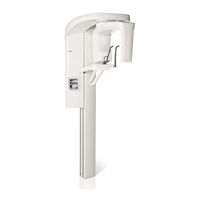
Sign In
Upload
Manuals
Brands
Planmeca Manuals
Medical Equipment
ProOne
Planmeca ProOne Manuals
Manuals and User Guides for Planmeca ProOne. We have
7
Planmeca ProOne manuals available for free PDF download: Technical Manual, User Manual, Manual, Installation Manual, Calibration Manual
Planmeca ProOne Technical Manual (195 pages)
Brand:
Planmeca
| Category:
Medical Equipment
| Size: 10.28 MB
Table of Contents
Table of Contents
3
Chapter A: GENERAL & TECHNICAL DATA
7
Intended Use
7
Software Version
7
Associated Documentation
7
Warnings and Cautions
8
Symbols on Product Labels
11
Symbols on Permanently Installed X-Ray Units
11
Symbols on X-Ray Units with Detachable Power Supply Cord
12
Technical Specifications
13
Technical Data
13
Original Manufacturer
14
Dimensions
15
X-Ray Field Area
16
Scattered Radiation Information
17
User's Statement
18
HANDLING PRECAUTIONS for Pcbs and SOFTWARE CHIPS
24
Handling Printed Circuit Boards
24
Handling EEPROM Memory Chips
24
Emc Information
25
Proone Web
29
Chapter B: SETTINGS
33
General about Settings
33
Contents of the Function Tabs
34
User Settings
35
User: Set Time and Date (U1100)
36
User: Select Language (U1200)
37
User: Operational Settings (U1300)
38
User: Network Settings (U1400)
41
User: Component Information (U1500)
43
User: Clinic Management (U1600)
44
Program Settings
45
Program: Program Licences (P2100)
46
Program: Program Presets (P2200)
48
Program: Functions after Exposure (P2300)
50
Program: Archive (P2400)
52
Program: Testing Programs (P2500)
53
Program: Imaging Without PC (P2600)
55
Technical Settings
58
Technical: Mode (T3100)
59
Technical: Exposures (T3200)
62
Technical: Troubleshooting (T3300)
64
Technical: Calibrations (T3400)
67
Technical: Update Software (T3500)
70
Technical: Factory Default Settings (T3600)
72
Technical: User-Specific Settings (T3700)
73
Chapter C: ERROR MESSAGES
77
Error Messages
78
Motorized Motion Related (E02-XXX)
78
X-Ray Generator Related (E03-XXX)
80
Communication Related (E04-XXX)
82
Power Supply Related (E05-XXX)
83
System Related (E06-XXX)
85
Calibration Related (E07-XXX)
85
Chapter D: PREVENTIVE MAINTENANCE
87
System Maintenance
87
Cleaning and Disinfection
87
Operating Checks
87
Indicator Lights for Ready Status and Exposure
87
Exposure Warning Signal
87
Exposure Switch
87
Emergency Stop Button
87
Labels
88
Preventive Maintenance Checks
89
Moving Column Slide Fixtures
89
Chapter E: CALIBRATIONS
91
Adjusting and Calibrating X-Ray Beam
91
Radiation Protection
91
Beam Checking Process from Step 1 to Step 8
92
Tools Required
93
Step 1: Adjusting the X-Ray Beam Position
94
Step 2: Adjusting the Patient Support Table Position (Ball Phantom Y-Line)
99
Step 3: Adjusting the C-Arm Position (Ball Phantom X-Line)
103
Step 4: Checking Symmetry (Ball Phantom X-Line)
106
Step 5: Adjusting the Positioning Lights
108
Adjusting the Layer Light Position
109
Adjusting the Midsagittal Plane Light Position
110
Adjusting the Frankfort Plane Light Position
111
Step 6: Calibrating the Sensor
113
Step 7: Taking Beam Check Exposure
113
Step 8: Taking a Ball Phantom Exposure
113
Calibrating Dynamic Exposure Control (Dec)
114
Chapter F: PARTS REPLACEMENT and REPAIR
119
Removing Column Covers
119
Opening the Front Panel
119
Removing C-Arm and Upper Arm Covers
120
Removing the Upper Arm Cover
121
Removing the Sensor Head Cover
122
Removing the Tube Head Covers
123
Removing the C-Arm Inner Cover
124
Column Parts Replacement
125
Replacing the Frankfort Plane Positioning Light
125
Replacing the Control Panel
126
Replacing the CPU PCB
128
Replacing Battery on CPU PCB
129
Replacing the Lift Motor
131
Replacing the Lift Motor Steel Cable
136
Replacing the Slide Fixtures
144
Arm and Upper Arm Parts Replacement
154
Replacing the Sensor Head
154
Replacing the Power Supply Unit (PSU) Assembly
156
Replacing the Tube Head
158
Filament Definition
161
Replacing the Collimator
162
Replacing the Layer Light
164
Replacing the Midsagittal Plane Positioning Light
165
Replacing the C-Arm Cables and the Cable Guide
166
Removing the Old Cables and Cable Guide
166
Installing the New Cables and Cable Guide
175
Chapter G: DIAGRAMS
185
Wiring Diagrams
186
Wiring Diagram for Permanently Installed X-Ray Units
186
Wiring Diagram for X-Ray Units with Detachable Power Supply Cord
187
PSU PCB (7005-10-01): Location of Indicators
188
PSU PCB (7005-10-01): Location of Connectors
190
Cpu Pcb
192
Location of Indicators and Connectors
192
Advertisement
Planmeca ProOne User Manual (116 pages)
Brand:
Planmeca
| Category:
Medical Equipment
| Size: 7.85 MB
Table of Contents
Table of Contents
3
Introduction
5
Symbols on Product Labels
6
Symbols on Permanently Installed X-Ray Units
6
Symbols on X-Ray Units with Detachable Power Supply Cord
7
Associated Documentation
8
Product Registration
8
Safety Precautions
9
Main Parts
12
General View of X-Ray System
12
General View of X-Ray Unit
13
Exposure Switch
14
Patient Supports
15
Emergency Stop Button
15
Switching X-Ray Unit on
16
Program Packages
17
Control Panel
18
General about Control Panel
18
Selecting Panoramic Exposure Program
19
Selecting Temporomandibular Joint (TMJ) Exposure Program
24
Selecting Sinus Exposure Program
29
Selecting Cross-Sectional Exposure Program (Optional)
32
Entering Patient Name
36
Selecting Patient Size
38
Selecting Kilovolt and Milliampere Values
39
Selecting Jaw Size and Shape
40
Adjusting Unit Height
41
Returning C-Arm to Patient Entry Position
42
Opening/Closing Temple Supports
42
Adjusting Layer Light Position
42
Switching DEC On/Off (Optional)
43
Switching Autofocus (AF) On/Off
43
Panoramic Exposure
44
Patient Positioning
45
Taking an Exposure
49
Temporomandibular Joint Exposure
52
Double TMJ Exposure (Lateral, PA or Lateral-PA)
52
Multi-Angle TMJ Exposure (3 Angles Lateral)
58
Sinus Exposure
63
Patient Positioning
64
Taking an Exposure
66
Cross-Sectional Exposure (Optional)
68
Patient Positioning
69
Taking an Exposure
73
Settings
76
User Settings
77
Program Settings
86
Help Messages
103
Error Messages
106
Cleaning and Disinfection
107
Patient Supports, Patient Handles and Control Panel
108
Other Surfaces
110
Service
111
Disposal
112
Technical Specifications
113
Technical Data
113
Original Manufacturer
114
Planmeca ProOne Technical Manual (84 pages)
Brand:
Planmeca
| Category:
Medical Equipment
| Size: 5.14 MB
Table of Contents
Table of Contents
3
Chapter a GENERAL & TECHNICAL DATA
5
Warnings and Cautions
5
Manual Versions
7
Symbols on Product Labels
7
Technical Specifications
8
Dimensions
9
X-Ray Field Area
10
User's Statement
11
HANDLING PRECAUTIONS for Pcbs and SOFTWARE CHIPS
17
Handling Printed Circuit Boards
17
Handling Software Flash Memory Chips
17
Emc Information
18
Chapter B PREVENTIVE MAINTENANCE
23
System Maintenance
23
Cleaning
23
Operator's Checks
23
Preventive Maintenance Checks
24
Chapter C C-ARM and UPPER ARM
25
Removing Covers
25
Removing the Upper Arm Cover
25
Removing the Sensor Head Cover
26
Removing the Tube Head Cover
27
Removing the C-Arm Inner Cover
28
Adjusting and Calibrating X-Ray Beam
29
Radiation Protection
29
Checking the X-Ray Unit Adjustments
30
Tools Required
31
Step 1: Adjusting the X-Ray Beam Position
33
Step 2: Adjusting the Patient Support Table in Y-Direction
37
Step 3: Adjusting the Patient Support Table in X-Direction
40
Step 4: Checking the Symmetry
42
Step 5: Adjusting the Positioning Lights
44
Step 6: Calibrating the Sensor
50
Step 7: Taking a Ball Phantom Exposure
55
Parts Replacement
57
Replacing the Sensor Head
57
Replacing the Tube Head/Psu
59
Replacing the Primary Collimator
61
Replacing the Layer Light
62
Replacing the Midsagittal Plane Positioning Light
63
Removing Covers
65
Opening the Front Panel
65
Parts Replacement
66
Replacing the Frankfort Plane Positioning Light
66
Replacing the Control Panel
67
Replacing the CPU PCB
68
Replacing the Lift Motor
69
Replacing the Lift Motor Steel Cables
74
Updating Software
79
Chapter E DIAGRAMS
81
Advertisement
Planmeca ProOne User Manual (70 pages)
Brand:
Planmeca
| Category:
Medical Equipment
| Size: 3.82 MB
Table of Contents
Table of Contents
3
1 Introduction
5
2 Symbols on Product Labels
6
3 Associated Documentation
6
4 Warnings and Precautions
7
5 Main Parts
9
General View of the System
9
General View of the X-Ray Unit
10
Exposure Switch
11
Patient Supports
12
Emergency Stop Button
12
6 Switching the X-Ray Unit on
13
7 Program Packages
14
8 Control Panel
15
Selecting Panoramic Exposure Program
15
Selecting Temporomandibular Joint (TMJ) Exposure Program
19
Selecting Sinus Exposure Program
23
Selecting Cross-Sectional Exposure Program (Optional)
26
Entering Patient Name
30
Selecting Patient Size
31
Selecting Kilovolt and Milliampere Values
31
Selecting Jaw Shape and Size
33
Adjusting Unit Height
34
Returning C-Arm to Patient Entry Position
34
Opening/Closing Temple Supports
34
Adjusting Layer Light Position
34
9 Panoramic Exposure
35
Patient Positioning
36
Taking an Exposure
39
10 Temporomandibular Joint Exposure
41
Double TMJ Exposure (Lateral, PA or Lateral-PA)
41
Multi-Angle TMJ Exposure (3 Angles Lateral)
47
11 Sinus Exposure
52
Patient Positioning
53
Taking an Exposure
56
12 Cross-Sectional Exposure (Optional)
57
Patient Positioning
58
Taking an Exposure
62
13 Cleaning
65
14 Service
65
15 Disposal
66
Planmeca ProOne Manual (57 pages)
Brand:
Planmeca
| Category:
Medical Equipment
| Size: 6.06 MB
Table of Contents
Table of Contents
3
1 Introduction
5
2 Associated Documentation
5
3 Pre-Installation Requirements
6
Safety Precautions
6
Environmental Requirements
7
Radiation Protection
7
Wall Strength
8
Electrical Requirements
8
Digital System Requirements
8
Network Architecture Requirements
9
Space Requirements
10
Dimensions for Wall Bracket and Optional Extension Plate
13
4 Main Parts
14
General View of the System
14
General View of the X-Ray Unit
15
5 Contents of the Packing
16
6 Unpacking the X-Ray Unit
17
7 Installing the X-Ray Unit
19
Attaching the X-Ray Unit to the Wall
19
Attaching the X-Ray Unit to the Floor
23
Attaching the Upper Arm Cover
26
Attaching the Safety Plate
26
Connecting the Power Cable
27
8 Installing the Exposure Switch
30
Movable Exposure Switch
30
Stationary Exposure Switch
32
9 Installing the Digital System
34
Connecting the Ethernet Cable
34
Configuring the Ethernet Link
35
Checking the Ethernet Link Communication
36
Installing the Romexis Imaging Software
36
Sensor Calibration Files
36
10 Post-Installation Check List
37
11 Diagrams
39
Planmeca ProOne Installation Manual (48 pages)
Brand:
Planmeca
| Category:
Medical Equipment
| Size: 7.69 MB
Table of Contents
Table of Contents
3
1 Introduction
5
2 Pre-Installation Information
6
Radiation Protection
6
Environmental Requirements
7
Power Requirements
7
Digital System Pre-Installation Information
7
Dimensions for X-Ray Unit
10
Dimensions for Wall Bracket and Extension Plate (Optional)
11
3 Contents of the Packing
12
Associated Documentation
12
Mounting Accessories
13
4 Main Parts of the X-Ray Unit
14
General View of the System
14
General View of the X-Ray Unit
15
5 Unpacking the X-Ray Unit
16
6 Installing the X-Ray Unit
18
Attaching the X-Ray Unit to the Wall
18
Attaching the X-Ray Unit to the Floor
19
7 Installing the Exposure Switch
22
Movable Exposure Switch
22
Stationary Exposure Switch
24
8 Installing the Digital System
26
Connecting the Ethernet Cable
26
Configuring the Ethernet Link
27
Checking the Ethernet Link Communication
28
Installing the Dimaxis/Romexis Imaging Software
29
Installing the Calibration Files
29
9 Checking the Alignments
30
X-Ray Beam
30
Taking a Ball Phantom Exposure
30
Patient Positioning Lights
30
10 Diagrams
31
Planmeca ProOne Calibration Manual (42 pages)
Brand:
Planmeca
| Category:
Medical Equipment
| Size: 2.22 MB
Table of Contents
Table of Contents
3
Chapter A: General Information
5
Disclaimer
5
Required Tools
7
Calibration Tools
7
Hand Tools
8
Chapter B: Pre-Check
9
Dimaxis 4.3
9
Ball Phantom Test
9
Measurement Tool Calibration
10
Measuring Image
10
Chapter C: Removing Covers
13
Upper Arm
13
Sensor Head
13
Inner Tubehead
14
Inner C-Arm
15
Chapter D: Alignment
17
Beam Adjustment
17
Vertical Alignment
19
High/Low
19
Angled
19
Horizontal Alignment
20
Left/Right
20
Ball Phantom Y-Line
21
Adjusting Y-Line
23
Ball Phantom X-Line
24
Adjusting X-Line
26
Checking the Symmetry
27
More than 1Mm Deviation
28
Positioning Lights
29
Layer
29
Adjusting the Light
31
Midsagittal
32
Frankfort
32
Adjusting the Light
33
Chapter E: Calibrating the Sensor
35
Proone Setup
35
Computer Setup
36
Calibration File Creation
37
Advertisement
Related Products
Planmeca ProMax
Planmeca ProX
Planmeca ProSensor HD
Planmeca Proline EC Panoramic
Planmeca ProMax Pan/Ceph
Planmeca Prostyle Intra
Planmeca Proline EC pan
Planmeca Proline EC ceph
Planmeca ProMax X-ray
Planmeca Proline XC Pan
Planmeca Categories
Medical Equipment
Dental equipment
Pet Care Product
3D Printers
Recording Equipment
More Planmeca Manuals
Login
Sign In
OR
Sign in with Facebook
Sign in with Google
Upload manual
Upload from disk
Upload from URL