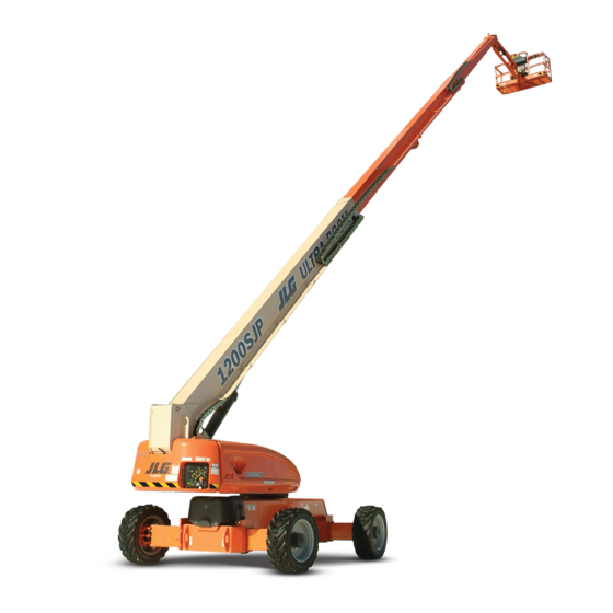
Sign In
Upload
Manuals
Brands
JLG Manuals
Lifting Systems
1200SJP
JLG 1200SJP Manuals
Manuals and User Guides for JLG 1200SJP. We have
6
JLG 1200SJP manuals available for free PDF download: Service Maintenance Manual, Service And Maintenance Manual, Operation And Safety Manual, Quick Reference
JLG 1200SJP Service Maintenance Manual (554 pages)
Brand:
JLG
| Category:
Boom Lifts
| Size: 42.74 MB
Table of Contents
Section No. Title Page no . Section a - Introduction - Maintenance Safety Precautions
5
General
3
Bhydraulic System Safety
3
Maintenance
3
Table of Contents
5
List of Figures Figure No. Title Page No.
19
Capacities
21
Caterpillar
21
Deutz BF4M2011 Specifications
21
Deutz Prior to S/N 0300127698
21
Deutz S/N 0300127698 to Present
21
Deutz TD2011L4 Specifications
21
Engine Data
21
Specifications
21
Tire Specifications
21
Tires
21
Chassis
22
Chassis Specifications
22
Dimensional Data
22
Reach Specifications
22
Specifications and Performance Data
22
Exxon Univis HVI 26 Specs
24
Mobil DTE 13M Specs
24
Mobil EAL H 46 Specs
24
Ucon Hydrolube HP-5046
24
Component Weights
25
Major Component Weights
25
Pressure Settings
25
Lubrication and Operator Maintenance
27
Annual Machine Inspection
37
General
37
Machine Preparation, Inspection, and Maintenance
37
Pre-Delivery Inspection and Frequent Inspection
37
Pre-Start Inspection
37
Preparation, Inspection, and Maintenance
37
Preventative Maintenance
37
Cleanliness
38
Components Removal and Installation
38
General
38
Inspection and Maintenance
38
Safety and Workmanship
38
Service and Guidelines
38
Battery
39
Bearings
39
Bolt Usage and Torque Application
39
Component Disassembly and Reassembly
39
Gaskets
39
Hydraulic Lines and Electrical Wiring
39
Hydraulic System
39
Lubrication
39
Lubrication and Servicing
39
Pressure-Fit Parts
39
Changing Hydraulic Oil
40
Cylinder Drift Test
40
Hydraulic Oil
40
Lubrication Specifications
40
Platform Drift
40
Cylinder Drift
41
Do NOT Do the Following When Welding on JLG Equipment
41
Do the Following When Welding on JLG Equipment
41
Pins and Composite Bearing Repair Guidelines
41
Welding on JLG Equipment
41
Inspection and Preventive Maintenance Schedule
42
Chassis & Turntable
47
Tire Damage
47
Tire Inflation
47
Tires & Wheels
47
Wheel and Tire Replacement
47
Wheel Installation
47
Wheel Torque Chart
47
Axle Limit Switch Adjustment Procedure
48
Extending Axles
48
Drive System
49
Steering Control System
49
Drive Orientation System
50
Drive/Steering Speed Control
50
Traction Control System
50
Steering Assembly Notes
59
Lockout Cylinder Bleeding
60
Oscillating Axle Bleeding Procedure and Lockout Test
60
Oscillating Axle System
60
Oscillating Axle Lockout Test
61
Disassembly
62
Disassembly of Cover
62
Disassembly of Second Stage Planet Gears (1)
62
Disassembly of the First Stage Planetary Assembly (7)
62
Drive Hub (Prior to S/N 100131)
62
Assembly of End Cover Unit (8)
63
Assembly of First Stage Planetary Assembly (7)
63
Final Assembly
63
Initial Start-Up and after Repairs
63
Oil Change Interval-Gear Drive
63
Drive Hub - Bonfiglioli (S/N 100128 to Present)
66
Hydraulic Motor Installation
66
Installation of the Wheel Drive on the Machine
66
Product Identification
66
Start up and Running in
66
Brake Technical Data
67
Connecting the Brake
67
Filling-Up the Gearbox with Lubricating Oil
67
General Information
67
Gearbox Disengagement
69
Suggested Lubricants According SAE 80W/90 and SAE 85W/140 API GL5 Grade
69
Changing the Lubricating Oil
71
Drive Hub Maintenance Schedule
71
Maintenance Information
71
Disassembly Information
72
Disassembly Procedure
72
Troubleshooting
72
Inspection of Parts
80
Assembly
81
Final Test and Reinstallation
91
Drive Hub - Reggiana Riduttori (S/N 134389 to Present)
96
Symbol Nomenclature
96
Tools
96
Disassembly
101
Assembly
105
Roll and Leak Testing
111
Swing Drive
111
Tightening and Torquing Bolts
111
Motor Control Valve Disassembly
112
Motor and Brake Disassembly
113
Main Disassembly
114
Hub-Shaft Disassembly
115
Carrier Disassembly
116
Hub-Shaft Sub-Assembly
117
Carrier Sub-Assembly
118
Main Assembly
120
Motor and Brake Assembly
122
Motor Control Valve Assembly
123
Pre-Installation Checks
124
Swing Brake
124
Assembly
125
Disassembly
125
Examination
125
Installation
125
Maintenance
125
Disassembly and Inspection
128
Swing Motor
128
Assembly
135
One Piece Stator Construction
142
Procedure for Setting Gear Backlash
143
Swing Drive Lubrication
144
Swing Bearing
145
Turntable Bearing Mounting Bolt Condition Check
145
Swing Bearing Removal
148
Wear Tolerance
148
Swing Bearing Installation
150
Swing Bearing Torque Values
151
Chassis Tilt Indicator System
152
Swing Speed Proportioning
152
Rotary Coupling
153
Coupling Port Information Table
157
Every 250 Hours
157
Every 500 Hours
157
Generator
157
Inspecting Brushes, Replacing Brushes, and Cleaning Slip Rings
158
Overload Protection
158
Auxiliary Power System
160
Changing Engine Oil
162
Checking Oil Level
162
Cold Weather Package
162
Engine
162
Glow Plugs
162
Changing the Oil Filter
163
Cleaning the Fuel Strainer
164
Replacing the Fuel Filter
164
Deutz EMR 2 (S/N 87579 to Present)
165
Bio Fuel
178
Bio Fuel in Deutz Engines
178
General
178
Biological Contamination in Fuels
179
List of Abbreviations in this Section
182
Can
184
Diagnostic Trouble Codes
184
J1939 Diagnostic Lamp Configuration
184
MIL Output
184
DTC 116- ECT Higher than Expected Stage 1
185
DTC 117- ECT/CHT Low Voltage
186
DTC 118- ECT/CHT High Voltage
188
DTC 122- TPS1 Signal Voltage Low
190
DTC 123- TPS1 Signal Voltage High
192
DTC 217- ECT Higher than Expected 2
194
DTC 219- RPM Higher than Max Allowed Governed Speed
195
DTC 336- Crank Signal Input Noise
196
DTC 337- Loss of Crank Input Signal
198
DTC 521- Oil Pressure Sender/Switch High Pressure
199
DTC 524- Oil Pressure Low
200
DTC 562- Battery Voltage (Vbat) Low
202
DTC 563- Battery Voltage (Vbat) High
204
DTC 601- Microprocessor Failure - FLASH
206
DTC 604- Microprocessor Failure - RAM
208
DTC 606- Microprocessor Failure - COP
210
DTC 642- 5 Volt External Low Voltage
212
DTC 643- 5 Volt External High Voltage
213
DTC 1612- Microprocessor Failure - RTI 1
214
DTC 1613- Microprocessor Failure - RTI 2
215
DTC 1614- Microprocessor Failure - RTI 3
217
DTC 1615- Microprocessor Failure - A/D
219
DTC 1616- Microprocessor Failure - Interrupt
221
DTC 1625- CAN J1939 Shutdown Request
223
DTC 1626- CAN J1939 Transmit (Tx) Fault
224
DTC 1627- CAN J1939 Receive (Rx) Fault
225
DTC 1628- CAN Address Conflict Failure
226
DTC 1629- J1939 TSC1 Message Reciept Loss
228
DTC 1652- TPS1 Loss of Communications
229
DTC 2111- Unable to Reach Lower TPS
230
DTC 2112- Unable to Reach Higher TPS
232
DTC 9999- Throttle Actuator Failsafe Spring Failure
233
DTC to SPN/FMI Table
234
Beyond Transport - Drive Speed Cutback System
235
Boom & Platform
235
Boom Systems
235
Broken Cable Indicator System
235
Platform Control Enable System
235
Transport Position Sensing System
235
Drive/Steer - Boom Function Interlock System (CE ONLY)
236
Envelope Tracking System
236
Jib Stow System
236
Boom Control System (BCS) Functional Check (Push to Test) System
237
Controlled Arc System
237
Moment Control System
237
Controlled Boom Angle System
238
Envelope Tracking
238
Slow down System
238
Dual Capacity System
239
Electronic Platform Leveling
239
Boom Control Select
240
Removal
241
Disassembly
250
Assembly
261
Boom Lubrication Application
277
Boom Shimming Procedure
277
Jib Lift End of Stroke Dampening
278
Jib Rotator Orientation
278
One Piece Bracket Maintenance
287
Powertrack Maintenance
287
Two Piece Bracket Maintenance
289
Snap Rings and Screws
290
Additional Replacement Criteria
298
Hose Routing Procedure
298
Inspection
298
Three Month Inspection
298
Wire Rope
298
Year or 7000 Hour Replacement
298
Boom Section Re-Positioning
299
Wire Rope Tensioning Adjustment
299
Wire Rope Tensioning Procedure
301
Adjusting the Proximity Switch
308
Broken Boom Cable Proximity Switch
308
Description
308
Electronic Platform Leveling
308
Normal Operation
309
Required Tools
310
Rotary Actuator
310
Theory of Operation
310
Disassembly
313
Assembly
317
Inspection
317
Bleeding after Installation
322
Installing Counterbalance Valve
322
Testing the Actuator
322
Cup and Brush
325
Hydraulics
325
Lubricating O-Rings in the Hydraulic System
325
Brush-On Method
326
Dip Method
326
Spray Method
326
Cylinder Repair
327
Disassembly
327
Cleaning and Inspection
336
Assembly
338
Holding Valve Torque Specifications
341
Cartridge Torque Values
347
Plug Torque Values
348
Hydraulic Tank
349
Pressure Setting Procedure
349
Set up of the Function Pump
349
Adjustments Made at the Main Valve Bank
350
Adjustments Made at the Frame Valve Bank
351
Adjustments Made at the Platform Valve Bank
355
Drive Pumps
356
Troubleshooting Procedure
356
Charge Pressure Relief Valve Adjustment
359
Hydraulic Centering of Control Modules
360
Mechanical Centering of Pump
360
High Pressure Relief Valve Adjustments
361
Removal and Inspection of Charge Pump
361
Torque Specs for Relief Valves into Port Block
361
Routine Maintenance
362
Removal and Installation of Shaft Seal
364
Function Pump
365
Spare Parts
365
Sealing the Drive Shaft
366
Disassembly and Assembly of the Complete Unit
367
Assembly
370
Adjustments
371
Tightening Torques
371
Pump Control Disassembly for Cleaning
373
Drive & Function Pump Start up Procedures
375
Start-Up Procedure
375
Introduction
377
Jlg Control System
377
Canbus Communications
378
Calibration Instructions
380
To Connect the JLG Control System Analyzer
390
Using the Analyzer
390
Adjusting Parameters Using the Hand Held Analyzer
392
Machine Setup
392
Machine Configuration Programming Information - Version P7.X to Present
393
Personality Ranges/Defaults
399
Machine Personality Settings/Function Speeds
403
Test Notes
403
System Test
404
Test from the Platform
404
Test from the Ground Station
407
System Test Messages
409
Machine Diagnostics Parameters
416
Calibrating Steer
422
Calibrating Drive
425
Electronic Platform Leveling
428
Fault Response
428
Platform Leveling Fault Warning
428
Additional Platform and Jib Valves
429
CAN Errors
429
Platform Leveling Calibration Procedure
430
Calibrating Platform Level
431
Step 2: Calibrating the Platform Level Sensors
432
Step 3: Bleeding the Platform Valves
433
Step 4: Calibrating the Platform Level up and down Valve Crackpoints
434
Calibrating Lift Crack Point
435
Calibrating Telescope Crack Point
438
Calibrating Tilt Sensor
441
Calibrating the Boom Sensors
443
Boom Control System Check Procedure
456
Diagnostic Trouble Code Chart
458
Canbus Troubleshooting
484
Canbus Communication Failure
491
Troubleshooting: Platform Can Communications Lost
492
Troubleshooting: BLAM Can Communications Lost
499
Troubleshooting: Chassis Can Communications Lost
502
Load Moment Pin Troubleshooting
504
Load Moment Pin Troubleshooting: Can Communications Lost
504
Load Moment Pin Troubleshooting: Moment Pin Horizontal Force out of Range
505
Load Moment Pin Troubleshooting: Moment Pin Vertical Force out of Range
506
Load Moment Pin Troubleshooting: Moment Pin Sensor Fault
507
Load Moment Pin Troubleshooting: New Moment Pin Detected Fault
507
Backprobing
509
Basic Electrical Information, Electrical & Hydraulic Schematics
509
General
509
Grounding
509
Min/Max
509
Multimeter Basics
509
Polarity
509
Scale
509
Voltage Measurement
509
Continuity Measurement
510
Resistance Measurement
510
Current Measurement
511
AMP Connector
512
Applying Silicone Dielectric Compound to AMP Connectors
512
Assembly
512
Disassembly
514
Service - Voltage Reading
514
Wedge Lock
514
Deutsch Connectors
516
DT/DTP Series Assembly
516
DT/DTP Series Disassembly
516
HD30/HDP20 Series Assembly
517
HD30/HDP20 Series Disassembly
517
Advertisement
JLG 1200SJP Service And Maintenance Manual (184 pages)
Brand:
JLG
| Category:
Boom Lifts
| Size: 50.89 MB
Table of Contents
General
3
Bhydraulic System Safety
3
Maintenance
3
Table of Contents
5
Specifications
23
Capacities
23
Tires
23
Engine Data
23
Deutz Prior to SN 0300127698
23
Deutz SN 0300127698 to Present
23
Deutz TCD 2.9
23
Deutz TCD 2.9 GUOIII
24
Specifications and Performance Data
24
Reach Specifications
24
Dimensional Data
24
Chassis
24
Torque Requirements
25
Hydraulic Oil
25
Major Component Weights
26
Pressure Settings
27
Lubrication and Maintenance
29
General
41
Machine Preparation, Inspection, and Maintenance
41
Preparation, Inspection, and Maintenance
41
Pre-Start Inspection
41
Pre-Delivery Inspection and Frequent Inspection
41
Annual Machine Inspection
41
Preventative Maintenance
41
Service and Guidelines
42
General
42
Safety and Workmanship
42
Cleanliness
42
Components Removal and Installation
42
Component Disassembly and Reassembly
43
Pressure-Fit Parts
43
Bearings
43
Gaskets
43
Bolt Usage and Torque Application
43
Hydraulic Lines and Electrical Wiring
43
Hydraulic System
43
Lubrication
44
Battery
44
Lubrication and Servicing
44
Lubrication and Information
44
Hydraulic System
44
Hydraulic Oil
44
Changing Hydraulic Oil
44
Lubrication Specifications
44
Cylinder Drift
45
Theory
45
Cylinder Leakage Test
45
Cylinder Thermal Drift
45
Pins and Composite Bearing Repair Guidelines
46
Welding on JLG Equipment
46
Do the Following When Welding on JLG Equipment
46
Do NOT Do the Following When Welding on JLG Equipment
46
Chassis & Turntable
52
Tires & Wheels
52
Tire Inflation
52
Tire Damage
52
Wheel and Tire Replacement
52
Wheel Installation
52
Extending Axles
53
Axle Limit Switch Adjustment Procedure
53
Drive System
54
Steering Control System
54
Drive/Steering Speed Control
55
Traction Control System
55
Drive Orientation System
55
Oscillating Axle System
70
Oscillating Axle Bleeding Procedure and Lockout Test
70
Lockout Cylinder Bleeding
70
Oscillating Axle Lockout Test
71
Wheel Drive Assembly
72
Removal
72
Installation
72
Drive Hub
73
Removal
73
Installation
73
Drive Motor
73
Removal
74
Installation
74
Disassembly
76
Disassembly of Cover
76
Disassembly of the First Stage Planetary Assembly (7)
76
Disassembly of Second Stage Planet Gears (1)
76
Assembly of First Stage Planetary Assembly (7)
77
Assembly of End Cover Unit (8)
77
Final Assembly
77
Initial Start-Up and after Repairs
77
Oil Change Interval-Gear Drive
77
Drive Hub - Bonfiglioli (SN 100128 to Present)
80
Product Identification
80
Hydraulic Motor Installation
80
Installation of the Wheel Drive on the Machine
80
Start up and Running in
80
General Information
81
Connecting the Brake
81
Filling-Up the Gearbox with Lubricating Oil
81
Gearbox Disengagement
83
Maintenance Information
85
Changing the Lubricating Oil
85
Troubleshooting
86
Disassembly Information
86
Disassembly Procedure
86
Inspection of Parts
94
Assembly
95
Final Test and Reinstallation
105
Drive Hub - Reggiana Riduttori (SN 134389 to Present)
110
Symbol Nomenclature
110
Tools
110
Disassembly
115
Assembly
119
Swing Drive
126
Roll and Leak Testing
126
Tightening and Torquing Bolts
126
Motor Control Valve Disassembly
127
Motor and Brake Disassembly
128
Main Disassembly
129
Hub-Shaft Disassembly
130
Carrier Disassembly
131
Hub-Shaft Sub-Assembly
132
Carrier Sub-Assembly
132
Main Assembly
133
Motor and Brake Assembly
134
Motor Control Valve Assembly
134
Swing Brake
137
Pre-Installation Checks
137
Installation
138
Maintenance
138
Disassembly
138
Examination
138
Assembly
138
Swing Motor
141
Disassembly and Inspection
141
Assembly
148
One Piece Stator Construction
155
Procedure for Setting Gear Backlash
156
Swing Drive Lubrication
157
Swing Bearing
158
Turntable Bearing Mounting Bolt Condition Check
158
Wear Tolerance
161
Swing Bearing Removal
161
Swing Bearing Installation
163
Swing Bearing Torque Values
164
Swing Speed Proportioning
165
Chassis Tilt Indicator System
165
Rotary Coupling
166
Generator
170
Every 250 Hours
170
Every 500 Hours
170
Overload Protection
171
Inspecting Brushes, Replacing Brushes, and Cleaning Slip Rings
171
Auxiliary Power System
173
Cold Weather Package
175
Engine
175
Glow Plugs
175
Checking Oil Level
175
Changing Engine Oil
175
Changing the Oil Filter
176
Replacing the Fuel Filter
177
Cleaning the Fuel Strainer
177
JLG 1200SJP Operation And Safety Manual (152 pages)
Brand:
JLG
| Category:
Boom Lifts
| Size: 16.52 MB
Table of Contents
Table of Contents
7
Section 1 - Safety Precautions
15
General
15
Pre-Operation
15
Operator Training and Knowledge
15
Workplace Inspection
16
Machine Inspection
17
Operation
17
General
17
Trip and Fall Hazards
18
Electrocution Hazards
19
Minimum Approach Distances (M.A.D.)
20
Tipping Hazards
21
Beaufort Scale (for Reference Only)
23
Crushing and Collision Hazards
24
Towing, Lifting, and Hauling
25
Maintenance
25
Maintenance Hazards
25
Battery Hazards
26
Section 2. User Responsibilities, Machine Preparation, and Inspection
27
Operator Training
27
Training Supervision
27
Operator Responsibility
28
2.2 Preparation, Inspection, and Maintenance
28
Inspection and Maintenance Table
29
Pre-Start Inspection
31
Function Check
35
Skyguard Function Test
37
Oscillating Axle Lockout Test (if Equipped)
38
Section 3 - Machine Controls and Indicators
39
3.1 General
39
3.2 Controls and Indicators
39
Ground Control Station
40
Ground Control Station with Machine Safety System
41
Ground Control Station
42
Ground Control Indicator Panel
47
Fuel Level Indicator
47
Platform Control Console
49
Platform Station
50
Platform Control Indicator Panel
57
Section 4 - Machine Operation
61
Description
61
Boom Operating Characteristics and Limitations
61
Capacities
61
Controlled Arc
62
Envelope Tracking
62
Controlled Angle
63
Swing Speed Proportioning
63
Stability
63
Position of Least Forward Stability
64
Engine Operation
65
Starting Procedure
65
Position of Least Backward Stability
65
Shutdown Procedure
67
Air Shutoff Valve (ASOV) (if Equipped)
67
Fuel Reserve / Shut-Off System
68
ASOV Reset (Open to Closed Position)
68
Grade and Side Slopes
70
Traveling (Driving)
71
Traveling Forward and Reverse
72
Traveling on a Grade
72
Steering
73
Extending the Axles
73
Platform
73
Platform Level Adjustment
73
Platform Rotation
73
Boom
74
Swinging the Boom
74
Raising and Lowering the Boom
74
Telescoping the Boom
74
Swinging the Jib
75
Function Speed Control
75
Machine Safety System Override (Msso)
75
(Ce Only)
75
4.11 Skyguard Operation
75
Skyguard
76
Skyguard - Skyline
76
Skyguard - Skyeye
76
Skyguard Function Table
77
4.13 Emergency Towing
78
Drive Disconnect Hub
78
4.14 Shut down and Park
79
4.15 Lifting and Tie down
79
Lifting
79
Tie down
79
4.16 Stowing the Jib for Transport
80
Lifting and Tie down Chart
81
Decal Legend
88
Section 5 - Emergency Procedures
99
General
99
Incident Notification
99
Emergency Operation
99
Operator Unable to Control Machine
99
Platform or Boom Caught Overhead or Boom Movement Prevented by Boom Control System
100
Emergency Towing Procedures
100
Machine Safety System Override (Msso)
101
(Ce Only)
101
Section 6 - Accessories
103
Available Accessories
103
Options/Accessories Relationship Table
104
Fall Arrest Platform
105
Safety Precautions
105
Pipe Racks
105
Capacity Specifications (Australia Only)
106
Safety Precautions
106
Preparation and Inspection
106
Operation
106
Skycutter
107
Safety Precautions
107
Accessory Ratings
108
Generator Output
108
Preparation and Inspection
108
Operation
108
Skyglazier
109
Capacity Specifications
109
Safety Precautions
110
Preparation and Inspection
110
Operation
110
Skypower
111
Generator Output
112
Accessory Ratings
112
Safety Precautions
112
Preparation and Inspection
112
Operation
112
Skywelder
113
Generator Output
113
Welding Accessories
113
Accessory Ratings
114
Safety Precautions
114
Preparation and Inspection
115
Operation
115
Bolt-On External Fall Arrest
116
Inspection before Use
116
Bolt-On External Fall Arrest Cable Tension
117
Bolt-On External Fall Arrest System
118
Section 7. General Specifications & Operator Maintenance
119
Operating Specifications
119
Dimensional Data
120
Chassis
121
Capacities
121
Tires
121
Tire Specifications
121
Engine Data - Deutz 2011
122
Deutz TD2011L4 Specifications
122
Deutz TCD 2.9L4 Specifications
122
Engine Data - Caterpillar
123
Hydraulic Oil
123
Caterpillar 3.4T Specifications
123
Hydraulic Oil Specifications
123
Mobilfluid 424 Specs
124
Mobil DTE 10 Excel 32 Specs
124
Ucon Hydrolube HP-5046
125
Mobil EAL H 46 Specs
125
Exxon Univis HVI 26 Specs
126
Component Weights
126
Engine Operating Temperature Specifications
127
Engine Operating Temperature Specifications - Caterpillar
130
Engine Operating Temperature Specifications - Caterpillar
131
Operator Maintenance
133
Lubrication Specifications
133
Tires & Wheels
146
Tire Damage
146
Tire Replacement
146
Wheel Replacement
147
Advertisement
JLG 1200SJP Operation And Safety Manual (116 pages)
Boom Lifts
Brand:
JLG
| Category:
Lifting Systems
| Size: 8.81 MB
Table of Contents
Table of Contents
7
Section 1. Safety Precautions
11
General
11
Pre-Operation
11
Operator Training and Knowledge
11
Workplace Inspection
12
Machine Inspection
12
Operation
13
General
13
Trip and Fall Hazards
13
Electrocution Hazards
14
Minimum Approach Distances (M.A.D.)
15
Tipping Hazards
16
Crushing and Collision Hazards
17
Towing, Lifting, and Hauling
18
Additional Hazards / Safety
19
Beaufort Scale (for Reference Only)
20
Section 2. User Responsibilities, Machine Preparation, and Inspection
21
2.1 Personnel Training
21
Operator Training
21
Training Supervision
21
Operator Responsibility
21
Preparation, Inspection, and Maintenance
22
Inspection and Maintenance Table
23
Pre-Start Inspection
24
Function Check
25
Boom Control System Check Procedure
26
Daily Walk-Around Inspection - Sheet 1 of 3
28
General
29
Daily Walk-Around Inspection - Sheet 3 of 3
30
Oscillating Axle Lockout Test (if Equipped)
31
Section 3. Machine Controls and Indicators
33
3.1 General
33
3.2 Controls and Indicators
33
Ground Control Station
33
Ground Control Station
34
Ground Control Indicator Panel
37
Platform Station
38
Platform Control Console - Prior to S/N 79596
40
Platform Control Console - S/N 79596 to 93078
41
Select
42
Platform Control Indicator Panel
47
Prior to S/N 79596
48
Present
49
Fuel Level Indicator
51
Section 4. Machine Operation
53
Description
53
Boom Operating Characteristics and Limitations
53
Capacities
53
Controlled Arc
54
Envelope Tracking
55
Controlled Angle
55
Swing Speed Proportioning
55
Stability
56
Capacity Select
56
Engine Operation
57
Starting Procedure
57
Shutdown Procedure
57
Fuel Reserve / Shut-Off System
58
Position of Least Forward Stability
59
Traveling (Driving)
60
Traveling Forward and Reverse
61
Steering
61
Extending the Axles
61
Grade and Side Slopes
62
Platform
63
Platform Level Adjustment
63
Platform Rotation
63
Boom
63
Swinging the Boom
64
Raising and Lowering the Boom
64
Telescoping the Boom
64
Swinging the Jib
64
4.10 Function Speed Control
64
4.11 Emergency Towing
65
4.12 Shut down and Park
66
4.13 Lifting and Tie down
66
Lifting
66
Tie down
67
JLG Lift
67
4.14 Stowing the Jib for Transport
67
Lifting and Tie down Chart - Sheet 1 of 2
68
Lifting and Tie down Chart - Sheet 2 of 2
69
Decal Location Sheet 1 of 5
70
Decal Location Sheet 2 of 5
71
Decal Location Sheet 3 of 5
72
Decal Location Sheet 4 of 5
73
Decal Location Sheet 5 of 5
74
Decal Legend - Prior to S/N 0300141473
75
Decal Legend - S/N 0300141473 to Present
79
Section 5. Emergency Procedures
83
General
83
Incident Notification
83
Emergency Operation
83
Operator Unable to Control Machine
83
Platform or Boom Caught Overhead
84
Boom Movement Prevented by Boom Control
84
System
84
Emergency Towing Procedures
84
Section 6. General Specifications & Operator Maintenance
85
Introduction
85
Operating Specifications
85
Operating Specifications - Prior to
85
Dimensional Data
86
Operating Specifications - S/N 0300141473 to
86
Chassis
87
Capacities
87
Chassis Specifications
87
Tires
88
Engine Data - Deutz Prior to S/N 0300127698
88
Tire Specifications
88
Deutz BF4M2011 Specifications
88
Engine Data - Deutz S/N 0300127698 to Present
89
Engine Data - Caterpillar
89
Deutz TD2011L4 Specifications
89
Caterpillar 3.4T Specifications
89
Hydraulic Oil
90
Mobil DTE 13M Specs
91
Mobil EAL H 46 Specs
92
Major Component Weights
93
Operator Maintenance
99
Tires & Wheels
107
Tire Replacement
108
Wheel Torque Chart
109
Supplemental Information
110
Inspection and Repair Log
111
JLG 1200SJP Operation And Safety Manual (128 pages)
Boom Lift Models
Brand:
JLG
| Category:
Lifting Systems
| Size: 3.82 MB
Table of Contents
Table of Contents
7
Section 1 - Safety Precautions
15
General
15
Pre-Operation
15
Operator Training and Knowledge
15
Workplace Inspection
16
Machine Inspection
17
Operation
17
General
17
Trip and Fall Hazards
18
Electrocution Hazards
19
Tipping Hazards
21
Crushing and Collision Hazards
24
Towing, Lifting, and Hauling
25
Maintenance
25
Maintenance Hazards
25
Battery Hazards
27
Section 2. User Responsibilities, Machine Preparation, and Inspection
29
2.1 Personnel Training
29
Operator Training
29
Training Supervision
29
Operator Responsibility
29
2.2 Preparation, Inspection, and Maintenance
30
Pre-Start Inspection
32
Function Check
33
Boom Control System Check Procedure
34
General
37
Oscillating Axle Lockout Test (if Equipped)
39
Section 3 - Machine Controls and Indicators
41
3.1 General
41
3.2 Controls and Indicators
41
Ground Control Station
41
Ground Control Indicator Panel
45
Platform Station
46
Platform Control Indicator Panel
55
Section 4 - Machine Operation
61
Description
61
Boom Operating Characteristics and Limitations
61
Capacities
61
Controlled Arc
62
Envelope Tracking
63
Controlled Angle
63
Swing Speed Proportioning
63
Stability
64
Capacity Select
64
Engine Operation
65
Starting Procedure
65
Shutdown Procedure
65
Fuel Reserve / Shut-Off System
66
Traveling (Driving)
68
Traveling Forward and Reverse
69
Steering
69
Extending the Axles
69
Platform
71
Platform Level Adjustment
71
Platform Rotation
71
Boom
71
Swinging the Boom
72
Raising and Lowering the Boom
72
Telescoping the Boom
72
Swinging the Jib
72
4.10 Function Speed Control
72
4.11 Emergency Towing
73
4.12 Shut down and Park
74
4.13 Lifting and Tie down
74
Lifting
74
Tie down
75
4.14 Stowing the Jib for Transport
75
Section 5 - Emergency Procedures
91
General
91
Incident Notification
91
Emergency Operation
91
Operator Unable to Control Machine
91
Platform or Boom Caught Overhead
92
Control System
92
Emergency Towing Procedures
92
Section 6 - General Specifications & Operator Maintenance
93
Introduction
93
Operating Specifications
93
Dimensional Data
94
Chassis
95
Capacities
95
Tires
96
S/N 0300127698
96
To Present
97
Engine Data - Caterpillar
98
Hydraulic Oil
98
Major Component Weights
102
Operator Maintenance
108
Tires & Wheels
120
Tire Inflation
120
Tire Damage
120
Tire Replacement
120
Wheel Replacement
121
Wheel Installation
121
Supplemental Information
122
JLG 1200SJP Quick Reference (1 page)
Brand:
JLG
| Category:
Boom Lifts
| Size: 0.08 MB
Advertisement
Related Products
JLG 120HX
JLG Toucan 12E
JLG Toucan 12E Plus
JLG 1230ES
JLG 1350SJP
JLG 1850SJ
JLG 1532E3
JLG 1932E3
JLG 10msp
JLG 19AMI
JLG Categories
Boom Lifts
Lifting Systems
Scissor Lifts
Construction Equipment
Forklifts
More JLG Manuals
Login
Sign In
OR
Sign in with Facebook
Sign in with Google
Upload manual
Upload from disk
Upload from URL