Sign In
Upload
Manuals
Brands
JLG Manuals
Lifting Systems
10msp
JLG 10msp Manuals
Manuals and User Guides for JLG 10msp. We have
5
JLG 10msp manuals available for free PDF download: Service Maintenance Manual, Service And Maintenance Manual, Operation And Safety Manual, Operation & Safety Manual
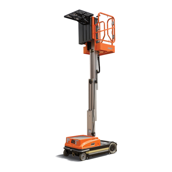
JLG 10msp Service And Maintenance Manual (178 pages)
vertical lift
Brand:
JLG
| Category:
Lifting Systems
| Size: 11 MB
Table of Contents
Table of Contents
5
Subject - Section, Paragraph
13
Section 1- Machine Specifications
13
Machine Operating Specifications
13
Capacities
14
System Voltage
14
Hydraulic System
14
Drive Motor Torque Hub (Gear Oil)
14
Component Data
14
Hydraulic Pump/Pump Motor Assembly
14
Rear Wheel Drive Motors
14
Batteries/Battery Charger
14
Performance Data
14
Platform Capacity
14
Platform Size
15
Material Tray Size
15
Platform Height (Fully Elevated)
15
Platform Maximum (Working) Height
15
Machine Height
15
Machine Overall
15
Platform Entry Height
15
Machine Ground Clearance
15
Machine Turning Radius (Outside)
15
Serial Number Plate Locations
15
Lubrication Specifications
16
Torque Specifications
17
Torque Chart - SAE Fasteners (Sheet 2 of 5)
18
Torque Chart - SAE Fasteners (Sheet 3 of 5)
19
Torque Chart - METRIC Fasteners (Sheet 4 of 5)
20
Torque Chart - METRIC Fasteners (Sheet 5 of 5)
21
General Service Information
23
Machine Preparation, Inspection, and Maintenance
23
General
23
Preparation, Inspection, and Maintenance
23
Pre-Start Inspection
23
Pre-Delivery Inspection and Frequent Inspection
23
Annual Machine Inspection
23
Preventative Maintenance
23
Preventive Maintenance and Inspection Schedule
24
Preventive Maintenance & Inspection Schedule
25
Servicing and Maintenance Guidelines
27
General
27
Safety and Workmanship
27
Cleanliness
27
Components Removal and Installation
27
Component Disassembly and Reassembly
27
Pressure-Fit Parts
27
Bearings
27
Gaskets
28
Bolt Usage and Torque Application
28
Hydraulic Lines and Electrical Wiring
28
Hydraulic System
28
Lubrication Information
30
Section 3 - Base Components
31
Base Assembly Components
31
Base Components (SN 0130032507 to Present)
32
Base Frame Covers
33
Drive Motor Cover
34
Drive and Caster Wheels
35
Front) Caster Wheel Installation
36
Wheel Drive Assembly Servicing
37
Drive Motor Brush Wear - Warning Indication
38
Wheel Drive Assembly Installation (Right Side Shown)
39
Wheel Drive Main Components Disassembly
40
Replacing Drive Motor Brushes
41
Torque Hub Main Disassembly
42
Input Carrier Disassembly
43
Hub Disassembly
44
Spindle Disassembly
45
Spindle Sub-Assembly
46
Hub Sub-Assembly
47
Input Carrier Sub-Assembly
48
Main Torque Hub Sub-Assembly
49
Motor, Brake, and Torque Hub Assembly
50
Pump Motor Assembly
51
Hydraulic Pressure Gauge Connection
52
Pump Motor Assembly Removal
53
Motor/Brush Cover Removal
54
Brush Carrier Assembly Removal
55
Filter Screen Removal
56
Battery Replacement
57
Battery Installation (2-12V)
57
Batteries and Battery Charger
57
Battery Installation (4-6V)
58
Battery Charge LED Indicator on Platform Control Console
59
Battery Low Voltage Warning Indicators
59
Battery Charging Status Indicators
60
Battery Charger Maintenance
60
Battery Charger Check/Change Charging Algorithm
61
Battery Charger Removal/Installation
61
Control Components
63
Control Components Overview
63
Control Components Location (SN 0130032507 to Present)
64
Control Components Installation
65
Ground Control Module
65
Traction Control Module Installation
66
Platform Control Console Installation
66
Platform Junction Box Installation
67
Junction Box to Ground Control Harness Installation
67
Platform Interlock Switch Circuit
68
Component Electrical Connections
69
Component Electrical Connections (4-6V Batteries)
70
Ground Control Module
71
Cover Removal/Installation
72
Power Selector/Emergency Stop Switch Installation
73
Ground Control Module Programming
74
General
74
Programming Levels
74
Activating Programming Mode
74
Entering Password
74
Programming Mode Selection
75
Selecting Programmable Item to Adjust
75
Adjusting Programmable Setting
75
Service Programming Mode - Level 2
76
Operator Programming Mode - Level 3
76
Field Programmable Settings and Factory Preset (Prior to SN 0130032507)
77
Field Programmable Settings and Factory Preset (SN 0130032507 to Present)
79
Platform Control Console
81
General
81
Display/Controller Module Electrical Connections
82
Mounting Bracket
82
Rear Cover
82
Display/Controller Module
83
Drive/Lift Mode Switch (Prior to SN 0130032507)
83
Horn Button Switch
83
Key Switch
83
E-Stop/Shutdown Switch
84
Joystick Assembly
84
Object Detection System (if Equipped)
85
Removal
85
Installation
85
Mast Components
87
Mast Components Overview
87
Mast Cover
88
Platform Assembly
88
Foot Height Limit Switch (if Equipped)
89
Manual Material Tray
89
Power Tray Disassembly
90
Covers and Tray Removal
90
Power Tray Roller Assembly
91
Electrical and Hydraulic Components Removal
92
Pulley System Disassembly
93
Pulley System Overview
94
Power Tray Lift Cylinder
95
Power Tray Installation
96
Pulley System Assembly
96
Electrical and Hydraulic Components Installation
98
Covers and Tray Installation
99
Hydraulic Line Disconnect Tool
99
In-Line Style Fittings
100
Angled-Style Fittings
101
Mast Removal
102
Mast Installation
102
Mast Disassembly
103
Procedure
103
Mast Section 4 (Platform Mount)
103
Mast Section 3
103
Mast Section 2
103
Mast Section 1
103
Cylinder Disassembly
104
Lift Cylinder Component Inspection
105
Cylinder Assembly
105
Manual Descent Valve
106
Remote Manual Descent (if Equipped)
106
Mast Assembly
107
Mast Section 1
108
Mast Section 2
108
Mast Section 3
111
Mast Section 4
113
Platform Junction Box to Ground Control Station Wiring Harness
116
Mast Chains and Sequencing Cables Adjustment
117
Mast Chain/Cable Adjustment
117
Sequencing Cable Adjustment
117
Mast Chain and Sequence Cable Adjustment Components
118
Troubleshooting
119
General
119
Troubleshooting Information
119
Hydraulic Circuit Checks
119
Electrical Circuit Checks
119
Multimeter Basics
120
Grounding
120
Backprobing
120
Min/Max
120
Polarity
120
Scale
120
Voltage Measurement
121
Resistance Measurement
121
Continuity Measurement
122
Current Measurement
122
Continuity Measurement over Long Distances
122
Requirements
122
Procedure
123
Electrical Switch Testing
123
Basic Check
123
Limit Switches
124
Automatic Switches
124
Switch Wiring - Low Side, High Side
124
Ground Control Module Lcd Display
125
Component Electrical Connections with 2-12V Batteries (Prior to SN 0130032507)
126
Component Electrical Connections with 4-6V Batteries (SN 0130032507 to Present)
127
LCD Display - Service Fault Code Conditions
128
Specifications for Various Components
132
Special Pin Extractor Tools for Electrical Connectors
132
Fault Code Troubleshooting Tables
133
Code 01 - Low Battery Voltage
134
Code 04 - Tilt Condition
135
Code 07 - Left Drive Motor - Disconnected
136
Code 09 - Left Brake - Disconnected
137
Code 11 - Left Drive Motor - Short Circuit
138
Code 13 - Traction Module - in Fold Back
139
Code 15 - Lift down Valve - Disconnected
140
Code 17 - Ground Control Module - in Fold Back
141
Code 19 - Alarm - Disconnected
142
Code 21 - Beacon - Short Disconnected
143
Code 23 - Horn - Disconnected
144
Code 25 - P1-Auxiliary #1 Circuit - Disconnected
145
Code 27 - P1-Auxiliary #2 - Disconnected
146
Code 30 - Traction Module - no Communication with Ground Control Module
147
Code 31 - Platform Control Console - no Communication with Ground Control Module
148
Code 32 - Pump Motor - over Current
149
Code 35 - P2-Auxiliary #1 - Tie-Down
150
Code 37 - Auxiliary #2 - Tie-Down
151
Codes (100 - 199) Ground Control Module - Fault Condition
152
Code (200 - 299) Platform Control Console - Fault Condition
153
Codes (300 - 399) Traction Control Module - Fault Condition
154
Main Power Circuit Troubleshooting
155
Machine will Not Power up
155
Mast Troubleshooting
156
Platform will Not Lower Manually
156
Platform Lift up and down Jerky
157
Mast Noisy When Lifting and Lowering
158
Platform (Mast) Won't Stay Elevated
159
Platform (Mast) Descends too Slowly
159
Hydraulic Leak Troubleshooting
160
Miscellaneous Hydraulic Leak Troubleshooting
160
Base Frame Components Troubleshooting
160
Caster Wheels Not Operating Freely
160
Drive System Troubleshooting
161
Won't Climb Grade
161
Machine Drives in Opposite Direction
161
Machine Won't Drive Straight
162
Noise from Drive Assembly
163
Electrical Components Installation (with 2-12V Batteries)
164
Electrical Components Installation (with 4-6V Batteries)
165
Electrical Components Installation (SN 0130032507 to Present)
166
Electrical Schematic - Sheet 1 of 2 (Prior to SN 0130032507)
168
Electrical Schematic - Sheet 2 of 2 (Prior to SN 0130032507)
169
Electrical Schematic - Sheet 1 of 4 (SN 0130032507 to Present)
170
Electrical Schematic - Sheet 2 of 4 (SN 0130032507 to Present)
171
Electrical Schematic - Sheet 3 of 4 (SN 0130032507 to Present)
172
Electrical Schematic - Sheet 4 of 4 (SN 0130032507 to Present
173
Hydraulic Schematic
174
Hydraulic Schematic -Power Tray (if Equipped)
175
Advertisement
JLG 10msp Service Maintenance Manual (196 pages)
Brand:
JLG
| Category:
Lifting Systems
| Size: 23 MB
Table of Contents
Introduction - Maintenance Safety Precautions
3
Hydraulic System Safety
3
Revision Log
5
Table of Contents
7
Section 1 Machine Specifications
9
Operating Specifications
9
Electrical Specifications
10
Performance Data
10
Platform Data
10
Serial Number Plate Locations
11
Torque Requirements
11
Cylinder Specifications
11
Lubrication
12
Lubrication Specifications
13
Thread Locking Compound
14
Torque Charts
15
SAE Fastener Torque Chart
15
Metric Fastener Torque Chart
27
Section 2 General Service Information
31
Machine Preparation, Inspection and Maintenance
31
Preventive Maintenance
31
Preventive Maintenance and Inspection Schedule
32
Servicing and Maintenance Guidelines
35
Safety and Workmanship
35
Lubrication Information
39
Section 3 Base Components
41
Base Assembly Components
41
Base Frame Covers
42
Drive Motor Cover
43
Drive and Caster Wheels
44
Front) Caster Wheel Installation
46
Drive/Elevation Cut-Out Switch Installation
46
Wheel Drive Assembly Servicing
47
Roll and Leak Testing
47
Drive Motor Brush Wear - Warning Indication
48
Wheel Drive Main Components Disassembly
49
Replacing Drive Motor Brushes
50
Input Carrier Disassembly
53
Hub Disassembly
54
Spindle Disassembly
55
Spindle Sub-Assembly
56
Hub Sub-Assembly
57
Input Carrier Sub-Assembly
58
Pump Motor Assembly
61
Hydraulic Pressure Gauge Connection
62
Pump Motor Assembly Removal
64
Motor/Brush Cover Removal
66
Brush Carrier Assembly Removal
67
Tank Removal
68
Filter Screen Removal
68
Pump Removal
69
Batteries and Battery Charger
70
Battery Replacement
71
Battery Installation
71
Battery Installation (4-6V)
72
Battery Charge LED Indicator on Platform Control Console
73
Battery Low Voltage Warning Indicators
74
Battery Charging Status Indicators
74
Battery Charger Maintenance
75
Battery Charger Check/Change Charging Algorithm
75
Battery Charger Removal/Installation
76
Section 4 Control Components
79
Control Components Overview
79
Control Components Installation
80
Ground Control Module
80
Traction Control Module Installation
81
Platform Control Console Installation
82
Platform Junction Box Installation
83
Junction Box to Ground Control Harness Installation
84
Platform Interlock Switch Circuit
85
Component Electrical Connections
85
Ground Control Module
86
Cover Removal/Installation
88
Power Selector/Emergency Stop Switch Installation
90
Ground Control Module Programming
92
Programming Levels
92
Activating Programming Mode
92
Entering Password
93
Programming Mode Selection
93
Selecting Programmable Item to Adjust
94
Adjusting Programmable Setting
94
Platform Control Console
98
Display/Controller Module Electrical Connections
99
Mounting Bracket
101
Rear Cover
101
Display/Controller Module
102
Horn Button Switch
102
Key Switch
103
E-Stop/Shutdown Switch
103
Joystick Assembly
104
Object Detection System (if Equipped)
105
Installation
106
Section 5 Mast Components
107
Mast Components Overview
107
Mast Cover
108
Platform Assembly
109
Foot Height Limit Switch (if Equipped)
109
Manual Material Tray
111
Power Tray Disassembly
111
Covers and Tray Removal
112
Electrical and Hydraulic Components Removal
116
Pulley System Disassembly
119
Power Tray Lift Cylinder
122
Power Tray Installation
123
Pulley System Assembly
123
Electrical and Hydraulic Components Installation
126
Covers and Tray Installation
127
Hydraulic Line Disconnect Tool
128
In-Line Style Fittings
128
Angled-Style Fittings
130
Mast Removal
132
Mast Installation
133
Mast Disassembly
133
Mast Section 4 (Platform Mount)
134
Cylinder Disassembly
135
Lift Cylinder Component Inspection
136
Cylinder Head
137
Tube Assembly
137
Cylinder Assembly
137
Manual Descent Valve
138
Remote Manual Descent (if Equipped)
138
Mast Assembly
139
Mast Chains and Sequencing Cables Adjustment
153
Section 6 Troubleshooting
155
General
155
Troubleshooting Information
155
Hydraulic Circuit Checks
155
Electrical Circuit Checks
156
Multimeter Basics
156
Voltage Measurement
157
Resistance Measurement
157
Continuity Measurement
158
Current Measurement
158
Continuity Measurement over Long Distances
159
Electrical Switch Testing
159
Limit Switches
160
Automatic Switches
160
Switch Wiring - Low Side, High Side
160
Ground Control Module LCD Display
161
Specifications for Various Components
166
Special Pin Extractor Tools for Electrical Connectors
166
Fault Code Troubleshooting Tables
167
Main Power Circuit Troubleshooting
180
Mast Troubleshooting
180
Platform will Not Lower Manually
180
Overview of Procedure
181
Mast Noisy When Lifting and Lowering
181
Platform (Mast) Won't Stay Elevated
182
Platform (Mast) Descends too Slowly
182
Hydraulic Leak Troubleshooting
183
Miscellaneous Hydraulic Leak Troubleshooting
183
Base Frame Components Troubleshooting
183
Caster Wheels Not Operating Freely
183
Drive System Troubleshooting
184
Machine Drives in Opposite Direction
185
Machine Won't Drive Straight
185
JLG 10msp Operation And Safety Manual (108 pages)
Brand:
JLG
| Category:
Lifting Systems
| Size: 7 MB
Table of Contents
Table of Contents
7
Section - Paragraph, Subject Page
11
Section 1 - Safety Precautions
11
General
11
Pre-Operation
12
Operator Training and Knowledge
12
Workplace Inspection
12
Machine Inspection
13
Operation
14
General
14
Trip and Fall Hazards
15
Electrocution Hazards
16
Minimum Approach Distances (M.A.D.)
16
Tipping Hazards
18
Crushing and Collision Hazards
19
Lifting and Hauling
20
General
20
Maintenance
21
Maintenance Hazards
21
Battery Hazards
22
Section 2 - Preparation and Inspection
23
Personnel Training
23
Operator Training
23
Training Supervision
24
Operator Responsibility
24
Machine Familiarization
24
Preparation, Inspection, and Maintenance
24
Inspection and Maintenance Table
25
Pre-Start Inspection
26
Walk-Around Inspection
27
Walk-Around Inspection
28
Walk-Around Inspection Components
29
Function Check
30
Function Check Items
30
Section 3. Machine Operation
34
General
34
Machine Description
34
Operating Characteristics and Limitations
35
Placards
35
Capacities
35
Stability
35
Machine Operation
36
Getting Started
36
Grade and Side Slope
36
Machine Operating Component Locations
37
Hood (Carry Deck)
38
Removal
38
Installation
38
Hood (Carry Deck) Removal
38
Battery Charging
39
Battery Low Voltage Warning Indicators
39
To Charge Batteries
40
Battery Charging Status Indicators
41
Battery Charger Location
41
Ground Control Station
44
Platform/Off/Ground Selector Switch
45
Emergency Stop/Shut down Button
45
Brake Release Button
46
Platform up and down Buttons
46
Machine Status LCD Display
47
LCD Display Symbols
47
Tilt Alarm Warning
48
LCD Display Fault Conditions
48
LCD Display - Operating Fault Conditions
49
Platform Control Console
52
General
53
Platform On/Off Key Switch
53
Platform Emergency Stop/Shut down Button
54
Horn Button
54
Joystick Function Enable Lever
55
Single Function Joystick Control
55
Drive Speed Setting Selector Switch
56
Platform Control Display Panel
57
Left Hand Lift
60
Platform Function Enable Footswitch
61
3.10 Platform Manual Descent Control Valve
62
Activating the Internal Manual Descent Valve
62
Internal Manual Descent Valve Location
62
Activating the Remote Manual Descent
63
Remote Manual Descent Location
63
3.11 Platform Configuration
64
Platform Lanyard Anchorage Point
64
Platform Maximum Capacity
64
Object Detection System (if Equipped)
65
Platform Gate Alarm
65
Object Detection System
65
Manual Tray Height Adjustment
66
Power Tray Height Adjustment
67
Cargo Strap (Option)
68
3.12 Parking Machine
68
Cargo Strap
68
Transporting, Lifting and Tie-Down Proce
69
General
69
Forklift Truck Transport
69
Vehicle Transport Using the Tie-Down Loops
70
Section - Paragraph, Subject Page
71
Programmable Security Lock (Psl ) (Option)
71
Machine Power up
71
Machine Power down
72
Changing the Operator's Code
72
3.15 Decal Installation
73
Manual Tray - Decal Installation
73
Manual Tray - Decal Installation
74
Manual Tray - Decal Installation
75
Power Tray - Decal Installation
77
Power Tray - Decal Installation
79
Power Tray - Decal Installation
80
Section 4 - Emergency Procedures
82
General Information
82
Emergency Operation
82
Operator Unable to Control Machine
82
Platform Caught Overhead
82
Incident Notification
83
Section 5. Accessories
84
Available Accessories
84
Scanner Pocket
85
Section 6. General Specifications and Operator Maintenance
86
6.1 Introduction
86
6.2 General Specifications
87
Machine Specifications
87
Electrical Specifications
88
Platform Data
88
Serial Number Location
89
Serial Number Plate Location
89
6.3 Operator Maintenance
90
Lubrication
90
Standard UTTO Specs
91
Ucon Hydrolube HP-5046 Specs
91
Lubrication Specifications
92
Lubrication Points
93
Lubrication Intervals for Various Components
94
6.4 Battery Maintenance
95
6.5 Tires and Wheels
95
Tire Wear and Damage
95
Wheel and Tire Replacement
95
Wheel Installation
96
Wheel Bolt Tightening Sequence
97
Wheel Torque Chart
97
6.6 Ground Control Station - Programming
98
General
98
Programming Levels
98
Operator Programming Mode
98
Tilt Sensor
98
Programming Items
99
Programmable Settings and Factory Presets
100
Activating Programming Mode
101
Entering Password
102
Programming Mode Selection
102
Selecting Programmable Item to Adjust
103
Adjusting Programmable Setting
103
6.7 Drive Motor Brush Wear - Warning Indication
104
Section 7. Inspection and Repair Log
106
Inspection and Repair Log
106
Advertisement
JLG 10msp Operation & Safety Manual (98 pages)
Brand:
JLG
| Category:
Lifting Systems
| Size: 6 MB
Table of Contents
Foreword
3
Revision Log
7
Table of Contents
9
Safety Precautions
11
General
11
Pre-Operation
12
Operator Training and Knowledge
12
Workplace Inspection
12
Machine Inspection
13
Operation
13
Electrocution Hazards
15
Tipping Hazards
16
Crushing and Collision Hazards
17
Lifting and Hauling
18
Maintenance
18
Maintenance Hazards
18
Battery Hazards
19
User Responsibilities, Machine Preparation, and Inspection
21
Personnel Training
21
Operator Training
21
Training Supervision
21
Operator Responsibility
22
Machine Familiarization
22
Preparation, Inspection, and Maintenance
23
Pre-Start Inspection
23
Walk-Around Inspection
24
Walk-Around Inspection Components
25
Function Check
26
Function Check Items
26
Machine Controls, Indicators, and Operation
29
General
29
Machine Description
29
Operating Characteristics and Limitations
29
Machine Operation
30
Getting Started
30
Hood (Carry Deck)
31
Installation
31
Battery Charging
32
Battery Low Voltage Warning Indicators
32
To Charge Batteries
34
Battery Charging Status Indicators
36
Ground Control Station
38
Brake Release Button
40
Platform Control Console
47
Horn Button
49
Platform Function Enable Footswitch
55
Platform Manual Descent Control Valve
56
Platform Configuration
57
Object Detection System (if Equipped)
58
Parking Machine
61
Transporting, Lifting and Tie-Down
62
Forklift Truck Transport
62
Programmable Security Lock
65
TM ) (Option)
65
Machine Power up
65
Machine Power down
65
Changing the Operator's Code
66
Decal Installation
66
Emergency Procedures
73
General Information
73
Emergency Operation
73
Incident Notification
74
Accessories
75
Scanner Pocket
75
General Specifications and Operator Maintenance
77
Introduction
77
Other Publications Available Specific to this Machine
77
General Specifications
77
Machine Specifications
77
Electrical Specifications
78
Platform Data
79
Serial Number Location
79
Operator Maintenance
80
Battery Maintenance
84
Tires and Wheels
84
Tire Wear and Damage
84
Wheel and Tire Replacement
84
Wheel Installation
85
Ground Control Station - Programming
86
Programming Levels
86
Operator Programming Mode
86
Programming Items
86
Activating Programming Mode
87
Entering Password
88
Programming Mode Selection
89
Selecting Programmable Item to Adjust
89
Adjusting Programmable Setting
90
Drive Motor Brush Wear - Warning Indication
90
Supplemental Information Only Applicable to CE/UKCA Machines
91
EC Declaration of Conformity
92
UKCA Declaration of Conformity
93
JLG 10msp Service And Maintenance Manual (61 pages)
Brand:
JLG
| Category:
Lifting Systems
| Size: 4 MB
Table of Contents
Maintenance Safety Precautions
3
Table of Contents
5
Section 1 - Machine Specifications
8
Capacities
8
System Voltage
8
Hydraulic System
8
Drive Motor Gearbox (Gear Oil)
8
Component Data
8
Hydraulic Pump/Pump Motor Assembly
8
Rear Wheel Drive Motors
8
Batteries/Battery Charger
8
Performance Data
8
Machine Height
9
Machine Overall
9
Platform Entry Height (Floor to Platform Floor)
9
Machine Ground Clearance
9
Machine Turning Radius (Outside)
9
Torque Requirements
9
Cylinder Specifications
9
Serial Number Locations
9
Lubrication
9
Hydraulic Oil
9
Torque Spscifications
11
Section 2 - General Service Information
13
General
13
Pre-Start Inspection
13
Annual Machine Inspection
13
Preventative Maintenance
13
Maintenance and Inspection Table Codes
14
Footnotes
14
Servicing and Maintenance Guidelines
15
General
15
Safety and Workmanship
15
Cleanliness
15
Tank Remove/Install
22
Filter Screen Remove/Install
23
Pump Remove/Install
23
Pressure Adjust Valve Remove/Install
23
Pressure Check Valve - Remove/Install
23
Batteries and Battery Charger -Service Procedures
24
Battery Condition Testing
24
Battery Replacement
24
Battery - Installation (2-12V Batteries)
24
Battery Installation - (4-6V Batteries) (OPTION)
24
Section 4 - Control Components
25
Ground Control Module
26
Entering Password
26
Programming Mode Selection
27
Selecting Programmable Item to Adjust
27
Adjusting Programmable Setting
27
General
29
Remove Platform Control Console
29
Display/Controller Module Electrical Connections
30
Mounting Bracket - Install/Remove
30
Rear Cover - Install/Remove
30
Display/Controller Module - Install/Remove
31
Drive/Lift Mode Switch - Install/Remove
31
Horn Button Switch - Install/Remove
31
Key Switch - Install/Remove
31
E-Stop/Shutdown Switch - Install/Remove
32
Joystick Assembly - Install/Remove
32
Advertisement
Related Products
JLG Toucan 12E
JLG Toucan 12E Plus
JLG 1200SJP
JLG 1850SJ
JLG 120HX
JLG 1532E3
JLG 1932E3
JLG 1932RS/6RS
JLG 15DVL
JLG 15DVSP
JLG Categories
Boom Lifts
Lifting Systems
Scissor Lifts
Construction Equipment
Work Light
More JLG Manuals
Login
Sign In
OR
Sign in with Facebook
Sign in with Google
Upload manual
Upload from disk
Upload from URL