
Related Manuals for Fimap IMx


Summary of Contents for Fimap IMx
- Page 1 WORKSHOP HANDBOOK Version: AB Date: October 29, 2013 Document Number:10043430/ATE...
- Page 2 Updates from the previous version. Section Page Since Serial Number 4.1.14 213009132 213008830 5.14.3 213008830 5.5.4 213009146 10.4...
-
Page 3: Table Of Contents
....... 19 4.1.9 BDI (Battery Discharge Indicator) IMx BB ... . . 19 4.1.10Function Switch IMx BB... - Page 4 ........32 4.4.2 Drive Shaft IMx BT .
- Page 5 ........51 5.11.1Battery Control Card (IMx BB only) .
- Page 6 6.4.2 Brass bushings ......64 Checks: ....... . . 64 Maintenance: .
- Page 7 8.3.1 Parking Brake Lever (IMx BT only) ....75 Procedure ....... . 75 8.4 Maintenance and Checks...
- Page 8 10.4.1Description ....... 86 10.4.2Tools needed for the installation ....86 10.4.3Machine Preparation .
-
Page 9: I Product Introduction
Part I Product Introduction... -
Page 10: Serial Number And Technical Support
1-10 Chapter 1 Serial Number and Technical Support The Serial Tag Serial Tag location To have access to the Serial Tag is necessary to remove the recovery tank. The Serial Number is an extremely important information which has to be provided each time a Technical Support is required or is necessary to buy spare parts or accessories. -
Page 11: Main Technical Features
2-11 Chapter 2 Main Technical Features TECHNICAL DESCRIPTION U/M IMx BB IMx B IMx BT Maximum Ramp Gradient Steering Diameter 1700 1700 1700 Machine Length 1200 1200 1200 Machine Height 1030 1030 1030 Machine Width (without squeegee) Machine Weight (empty and without batter-... -
Page 12: Anomalies Resolution Guide
2-12 Part II Anomalies Resolution Guide... -
Page 13: Trouble-Shooting For The Most Common Anomalies
3-13 Chapter 3 Trouble-shooting for the most common anomalies. Electrical system: what to do if. . . The machine doesn’t switch on 1) (Only B-BT) The key is in position 0 Rotate the key in position I. 2) (Only BB) The main switch is in po- Push the switch in position I or II. - Page 14 The batteries don’t work properly 1) The batteries are not properly con- Restore the proper battery connec- nected tions. 3-14 2) Battery are discharged Perform a complete charge cycle. 3) Battery terminal are oxidized Disconnect the batteries, clean the batteries terminals and reconnect properly the batteries.
- Page 15 (Only B-BT) The display shows an alarm message 1) The display shows an alarm mes- Check what alarm message is sage shown and solve the related issue 3-15 by following the proper instructions (see section 5.13.1 at page 54) The machine has a very limited working autonomy 1) The batteries connections are oxi- Unplug the connection wires, wash dized...
-
Page 16: Frame And Traction System: What To Do If
Frame and traction system: what to do if. . . 3-16 (Only BT) The traction motor doesn’t work properly 1) The machine is switched off Switch on the machine. 2) The machine doesn’t switch on Check the proper section (see section at page 8) 3) The display shows an error mes- Check the proper section. -
Page 17: Mechanical Scrubbing System: What To Do If
Mechanical scrubbing system: what to do if. . . 3-17 The machine doesn’t clean well The machine is switched off Switch on the machine. The machine doesn’t switch on Refer to the proper section (see section at page 8) (Only B-BT) The display shows an Refer to the proper section (see section alarm message... -
Page 18: Solution Delivery System: What To Do If
Solution delivery system: what to do if. . . 3-18 The delivered solution is not correct or not enough 1) The machine is switched off Switch on the machine. 2) The machine doesn’t switch on Refer to the proper section (see section at page 8) 3) The solution tank is empty... -
Page 19: Drying System: What To Do If
Drying system: what to do if. . . 3-19 The machine doesn’t dry well The machine is switched off Switch on the machine. The machine doesn’t switch on Refer to the proper section (see section at page 8) The vacuum motor is switched off Switch on the vacuum motor. - Page 20 The vacuum motor doesn’t work properly 1) The vacuum motor is not powered Check the power connections on the properly vacuum motor. 3-20 2) (Only vacuum motor Replace the vacuum motor switch. switch doesn’t work 3) (Only B-BT) The display shows an Refer to the proper section (see section alarm message...
-
Page 21: Disassembling Procedures
Chapter 4 4-21 Disassembling Procedures ARNING EFORE TO PERFORM ANY OPERATION DESCRIBED BELOW VERIFY THAT THE MACHINE TANKS ARE COMPLETELY EMPTY THE MACHINE HAS TO BE TURNED ISCONNECT THE BATTERIES AND REMOVE THEM FROM THE MACHINE T LAST VERIFY THAT THE PARKING BRAKE IS ENGAGED AND THE MACHINE IS IN A TOTALLY SAFE CONDITION... -
Page 22: Electrical Installation
Philips screw driver small medium 4-22 4.1.2-1 Screw driver small and medium 4.1.3 Display Card IMx B/BT Wrench: Put the machine in safe conditions. – n. 2,5 Remove the Function Dashboard (see – n. 5,5 section 4.1.2 at page 17) –... -
Page 23: Power Card Imx B/Bt
4.1.4-4 Unplug the Vacuum Hose (see fig. 4.1.6-8) Unhook the Drain Hose from its Clip (see fig. 4.1.6-8) 4.1.5 Power Card IMx B/BT Remove the Function Dashboard (see Put the machine in safe conditions. fig. Remove the Function Dashboard (see... -
Page 24: Buzzer Imx B/Bt
(see fig. 4.1.8-14) Remove the Key Switch. 4.1.6-10 4.1.6-11 Proceed at reverse to refit the part. 4.1.7 Buzzer IMx B/BT Put the machine in safe conditions. Remove the Function Dashboard (see section 4.1.2 at page 17) Remove the Rear Dashboard (see section 4.1.6... -
Page 25: 10Function Switch Imx Bb
Vacuum Motor Contactor (Rif. RVA) (see fig. 4.1.9-17 Loose the screws that block the Vac- uum Motor Contactor to the Electric 4.1.10 Function Switch IMx BB Panel (see fig. 4.1.11-19) Put the machine in safe conditions. Remove the Vacuum Motor Contac- tor. -
Page 26: 13Brush Release Switch Imx Bb
Remove the screws that secure the 4.1.13 Brush Release Switch microswitch support to the handle- IMx BB (see fig. 4.1.14-24) (see fig. 4.1.14-25) Put the machine in safe conditions. Remove the Dead Man Switch. Remove the Function Dashboard (see Proceed at reverse to refit the part. -
Page 27: 15Battery Charger Imx Cb
4.1.15 Battery Charger IMx CB Put the machine in safe conditions. Remove the Function Dashboard (see section 4.1.2 at page 17) Remove the Rear Dashboard 4-27 (see section 4.1.6 at page 18) Loose the screws that block the Bat- tery Charger Cover. -
Page 28: Mechanical Friction System
Mechanical Friction System 4.2.1 Tools needed Pincer for hose clamps 4-28 4.2.2-29 4.2.2-30 Pincer for Seeger Wrench n. 13 Allen key n. 4 Socket screw driver n. 7 4.2.2-31 4.2.2-32 4.2.2 Brush Deck Assembly Release the brush from the Brush Deck. -
Page 29: Brush Coupling Flange
4.2.3 Brush Coupling Flange Put the machine in safe conditions. Disassemble the Brush Deck from the machine (see section 4.2.2 at page 23) 4-29 4.2.4-38 Put the Brush Deck to let the Motor Head touch the floor (or a table). 4.2.5 Brush Motor Unscrew the Coupling Flange rotat-... -
Page 30: Bumper Wheel
4.2.6 Bumper Wheel Release the Brush from the Brush deck (see fig. 4.2.2-29) Put the machine in safe conditions. 4-30 Tilt the machine in the parking con- ditions. Loose the upper bushing of the Bumper Wheel (see fig. 4.2.6-42) Remove the Bumper Wheel. Proceed at reverse to refit the part. -
Page 31: Drying System
Drying System 4.3.2 Squeegee Adapter Put the machine in safe conditions. 4.3.1 Squeegee Disassemble the Squeegee from the Put the machine in safe conditions. Machine (see section 4.3.1 at page 26) Lower the Squeegee in working con- 4-31 Loose the knobs that block the ditions. -
Page 32: Squeegee Adjustment Wheels
4.3.4 Squeegee adjustment Proceed at reverse to refit the part, paying attention to take care about wheels the bushing positioning. Put the machine in safe conditions. Remove the squeegee support (see sec- 4-32 tion 4.3.3 at page 26) Remove the squeegee adjustment knob and the spring (see fig. -
Page 33: Vacuum Hose
4.3.7 Recovery Tank Put the machine in safe conditions. Uncouple the Vacuum Hose from the Recovery tank Inlet (see fig. 7.4.3-20) Unplug the Vacuum Manifold from 4-33 4.3.5-54 4.3.5-55 the Recovery Tank (see fig. 4.3.7-60) Uncouple the Drain Hose from the 4.3.6 Vacuum Hose clip and let it lie on the floor... -
Page 34: Drain Hose
4.3.9 Vacuum Filter Put the machine in safe conditions. Remove the Recovery Tank Lid (see fig. 4.3.9-65) 4-34 Uncouple the Filter Cover. (see fig. 4.3.9- 4.3.7-59 4.3.7-60 Remove the Vacuum Filter pulling it down (see fig. 4.3.9-67) Proceed at reverse to refit the part. 4.3.7-61 4.3.7-62 4.3.9-65... -
Page 35: 11Squeegee Lifting Chain
4.3.11 Squeegee Lifting Chain Unplug the electric connection of the Vacuum Motor (see fig. 4.3.10-70) Put the machine in safe conditions. Loose the screws that block the Vac- Disassemble the Squeegee from the uum Motor to the Solution Tank (see Machine (see section 4.3.1... -
Page 36: 12Squeegee Lifting Lever
4.3.12 Squeegee Lifting Lever Put the machine in safe conditions. Disassemble the Squeegee from the Machine (see section 4.3.1 at page 26) 4-36 Be sure that the Squeegee Com- mand Lever is in lower position. Unscrew the screw that fix the chain to the Squeegee Command Lever and let it lie behind the Squeegee Sup- port... -
Page 37: Frame And Traction System
4.4.1-77 Unplug the Electrical connector of the Traction Gearmotor (see fig. 4.4.3-81) 4.4.2 Drive Shaft IMx BT Loose the screws that block the Traction Gearmotor to the Machine Put the machine in safe conditions. Frame (see fig. 4.4.3-82) -
Page 38: Parking Wheel
4.4.5 Parking Wheel Put the machine in safe conditions. Tilt the machine to lower the brush deck on the floor. 4-38 Loose the bolt that blocks the wheel 4.4.3-81 4.4.3-82 to the Machine Frame (see fig. 4.4.5-86) Remove the Parking Wheel. Remove the bushing from the wheel. -
Page 39: Parking Brake Imx Bt
4.4.6 Parking Brake IMx BT Put the machine in safe conditions. Remove the screws that secure the Support Bracket of the Parking Brake to the machine frame (see fig. 4-39 4.4.6-87) Remove the Parking Brake from its Support Bracket. Proceed at reverse to refit the part. -
Page 40: Solution Delivery System
Solution Delivery Sys- 4.5.1 Solution Tank Put the machine in safe conditions. 4-40 4.5.1-88 4.5.1-89 Remove the recovery tank. (see section 4.3.7 at page 28) Disconnect the water supply hose from the solenoid valve. Loosen the screws securing the so- lution tank to the scrubdeck (see fig. -
Page 41: Hoses
4.5.2 Hoses 4.5.4 Water Valve Put the machine in safe conditions. Put the machine in safe conditions. Loose the clamps that block the hose Unplug the hoses from the Water to the fitting. Valve loosing the hose clamps (see fig. 4.5.4-98) (see fig. -
Page 42: Solenoid Valve
4.5.5 Solenoid Valve Put the machine in safe conditions. Remove the Brush Deck Assembly (see fig. 4-42 Unplug the hoses connected to the Solenoid Valve (see fig. 4.5.5-102) Loose the plastic nut that block the Solenoid Valve to its support (see fig. -
Page 43: Machine Description
4-43 Part III Machine Description... -
Page 44: Electrical System
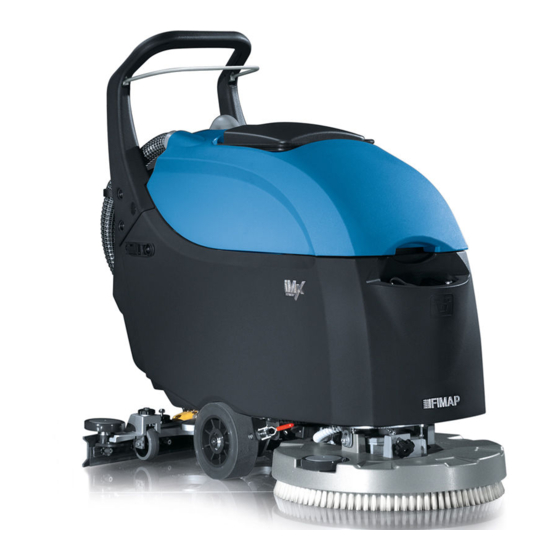
IMx scrubber dryer machine is avail- 7. Charger able in three different versions: IMx B, 8. Safety lever IMx BB and IMx BT. The IMx BB is electromechanical without traction mo- 9. Batteries tor and speed regulation. The IMx B and IMX BT are equipped with control card. -
Page 45: Structure Imx B/Bt
The dash board can be used also as a programmer console to mod- Figure 5.2: Electrical System IMx B/BT ify the parameter of all the machine’s functions (traction, vacuum and wash- ing) and, also, to check the consumption of all the motors and batteries. -
Page 46: Location Of Electrical Components
Location of Electrical components 5.5.1 IMx BB 5-46... -
Page 47: List Of Components
List of Components AP-AP 50A Batteries contact CBR Charger CTR Hourmeter and Battery control card EL Solenoid Valve FAS Fuse of Vacuum Motor 5-47 FBR Fuse of Brush Motor IGEN Main switch IMVA Vacuum Motor Switch MBR Brush Motor MP Safety Micro MVA Vacuum Motor RBR Remote control switch Brush Motor RVA Relay Vacuum Motor... -
Page 48: Imx B/Bt
5.5.2 IMx B/BT 5-48... -
Page 49: List Of Components
List of Components AP-AP 50A Batteries connection BEP Buzzer CBR Charger CD Control Card CH Main switch 5-49 EL Solenoid Valve J Main Card M1 Traction Motor MBR Brush Motor MP Safety Micro MVA Vacuum Motor Switch POT Potentiometer Optional BT Only... -
Page 50: Main Card (Imx B/Bt)
WHEREAS TO ENTER INTO THE ” VANCED MENU A PASSWORD IS NEEDED Output Signals VA Supply to Vacuum Motor BR Supply to Brush Motor M1 Supply to Traction Motor M2 Supply to Traction Motor 5.5.4-1 Dashboard IMx B 5.5.4-2 Dashboard... -
Page 51: Functions And Commands
10 5.5.4-3 Battery Control 5.5.4-4 Battery Control Card Card Function of the buttons - IMx B/BT Not Used Not Used ENTER (Confirm) SCROLL UP/PLUS (Scroll up and In- crease) RESET Confirmation... -
Page 52: Operator Menu
Operator Menu For example, to modify the language from EN to IT To enter to the Operator menu go ahead Turn OFF the machine as follow: Press in the same time, the buttons With the machine off, press in the “3”, “4”... -
Page 53: Advanced Menu
Advanced Menu Parameters Reset The Advanced Menu can be reached Some parameters of the Advanced Menu from the “operator menu” by accessing (Brushes Sets, Pumps Sets, Vacuum the “password” parameter and setting Sets, Traction Sets) can be restored to the value 60. the factory setting. -
Page 54: Control Card
Check/Monitor submenu Safety Microswitch To exit form the “Check/Monitor” view, turn OFF and ON the machine. All the IMx versions are equipped with a safety microswitch, located inside of the 5.5.5 Control Card handle of the machine and operated by... -
Page 55: Hourmeter (Imx Bb Only)
5-55 Hourmeter (IMx BB 5.10 Batteries only) The machine is equipped with an elec- On the machine is possible to install two tronic hourmeter, installed on the dash- different type of batteries: 12V 77Ah and board. The hourmeter shows the battery 12V 62Ah (2 batteries for each type on charge level by its leds. -
Page 56: Adjustments
Battery Control Card supply, a red led will blink once, the (IMx BB only) yellow led blink once and the green led blink depending of the type of battery for Check that, when turning on the ma- which the charger is set. -
Page 57: Charging Curve Setup
Overtemperature alarm ing table shows how to setup the dip- switches 1 and 2 Set-up of Charging Curve 5.11.3 ECO Function (solo IMx DP1 DP2 Set-up Flash B/BT) OFF OFF Wet cell batteries Press the ECO button, and let the vac- Gel TROJAN uum motor and the brush motor work. -
Page 58: Maintenance And Checks
5.12 Maintenance Checks 5.12.1 Electrical System Checks Check the functions and the proper con- nections of the switches, microswitches, motors, solenoid valve, contactors, re- 5-58 lay, fuses, thermal fuses and cables. Check periodically, the wiring connec- tions. To check the wiring, remove the control panel and the rear cover. -
Page 59: Alarm Table (Imx B/Bt Only)
AL 16: Traction Power of traction damage Replace the main card. This alarm could be shown also during Power damage the trailing of the machine. (IMx BT) AL 17: Traction Traction Overcurrent Detected a shortcircuit on the traction motor output: Check Overcurrent connections and traction motor (IMx BT). -
Page 60: Menu Tables (Imx B/Bt Only)
5.14 Menu Tables (IMx B/BT only) 5.14.1 Menu Tree Make sure the machine is turned off. Press simultaneously the buttons 3,4,6. Turn on the machine while holding down the buttons. Wait the loading of the Operator Menu. 5-60 For the submenus of the Advanced Menu, refer to the specific tables. -
Page 61: 2Working Menu
MENU DEFAULT CHOICES DESCRIPTION General Setup: IT-EN-FR-SP Setup language Language: ## General Setup: IMX BT IMX B - IMX Setup type of machine Mod: ####### General Setup: GEL-WET- Setup kind of battery Battery: ### AGM-GE1- General Setup: Reset partial hourmeter. -
Page 62: General Sets
DESCRIPTION General Sets: IT-EN-FR-SP Setup the language of the display. Language: ## General Sets: IMX-BT IMX B - IMX Setup of the machine model (Normal version or with dosing Mode: ## system). General Sets: GEL-WET- Setup of the battery type. -
Page 63: Pumps Sets
Pumps Sets Parameter Default Description Pumps Sets: 10.0 First level of water flow of the proportional solenoid valve. Wtr Lev1: ### [V] Pumps Sets: 11.0 Second level of water flow of the proportional solenoid valve. Wtr Lev2: ### [V] Pumps Sets: 13.5 Third level of water flow of the proportional solenoid valve. -
Page 64: Traction Sets
Traction Sets Parameter Default Description Traction Sets: Acceleration ramp. The time necessary to arrive at the maximum Acc Ramp: #.# [s] speed. Traction Sets: Deceleration ramp. The time necessary to stop the machine when the Dec Ramp: #.# [s] safety lever is released. Traction Sets: The time necessary to invert the way. -
Page 65: Check / Monitor
Show temperature inside of main card, related to brush/vacuum. BR Temp: ## [C] Check / Monitor: Show temperature inside of main card, related to traction (IMx BT only). TR Temp: ## [C] Check / Monitor: Show the percentage value of the amperometric protection of traction motor (when 100% TR Ovrld: ### [%] the amperometric protection cuts the current). -
Page 66: Technical Features
437657 CHARGER NE286 24V 11A 210516 COMPLETE KEY SWITCH (ELFI D.22) 436267 CONTROL CARD 438057 MAIN CARD IMX COD.7CFS0000 438158 POTENTIOMETER 407578 DOUBLE REMOTE CONTR SW. 24V 100A SW84-P 407580 RELAY FINDER 65.31 30 A, 24 V SUCT. MOT. 409607... -
Page 67: Structure
Chapter 6 Mechanical Rubbing System Description 6-67 The washing function of the machine is obtained by the interaction of the cleaning solution with the dirt present on the floor. To facilitate and enhance this interaction, is used a system of mechanical rubbing which consists in a device which rubs on the floor. -
Page 68: Adjustments
Adjustments Maintenance: Motor carbon brushes replacement: 6.3.1 Adjustment system Procedure: The base must be free to move pivoted to its support so that the brush acts paral- Secure the machine. lel to the floor. This allows the brush to evenly lean Remove the base from the machine. -
Page 69: Brass Bushings
6.4.2-7 Base fixing screws 6.4.2-8 Base fixing screws 6-69 Replace the carbon brushes being careful not to ruin them during as- sembly. (see fig. Proceed to the reverse operations to reassemble it all. 6.4.2 Brass bushings Remove the bushings and replace Checks: them with new bushings. -
Page 70: Bumping Wheel
6.4.3 Bumping Wheel 6.4.6 Fixing adjustment plate Checks: Checks: The bumping wheel must be free (see fig. to rotate and its diameter must not be The fixing plate must be in (see fig. too small due to wear. A bumping wheel good condition, must not show signs of in poor condition can lead to cracking of corrosion or deformation. -
Page 71: Technical Features
Technical Features TECHNICAL DESCRIPTION IMx BB IMx B IMx BT Working width Working capacity, up to m2/h 2032 2032 2032 Number of brushes Maximum diameter of the active part of the brush Brush turns Brush motor voltage Brush motor power... -
Page 72: Drying System
Chapter 7 Drying System Description The machine dries the floor using an in- tegrated Drying System. After the wash- ing, the solution used with the mechan- ical action of the brush to remove the 7-72 dirt, is collected by a system which vac- uum it out from the floor. -
Page 73: Adjustments
Adjustments Procedure Put the machine in safe conditions. 7.3.1 Squeegee Support Lower the squeegee on the floor. The Squeegee Support has to be ad- justed with the Squeegee fitted on, low- Act on the wheel nuts (see fig. 7.3.1-9) ered on the floor and vacuum system on. until the wheels are lifted 1,5 mm The goal of the adjustment is to let the ( 0,1mm eventually help the adjust-... -
Page 74: Squeegee
Maintenance Checks 7.4.1 Squeegee Checks 7.4.1-11 Front Rubber 7.4.1-12 Front Rubber To have a good performance of the squeegee the blades have to be in a good conditions. The squeegee chamber and the squeegee adapter have to be clean and completely free from debris. Blades have to adhere perfectly to the squeegee body and have to be kept in that posi- 7.4.1-13 Front Rubber... -
Page 75: Maintenance
7.4.3 Vacuum Hose Maintenance Put the machine in safe conditions. Checks The vacuum hose has to be clean and Remove squeegee from intact . It is squeegee support (see fig. 7.4.3-20) (see fig. 7.4.3-21) (see fig. 7.4.2-17) (see sec- mandatory that the hose has no crack to tion 4.3.1 at page 26) -
Page 76: Recovery Tank
Remove and clean (replace if neces- sary) the filter. 7.4.5-25 Vacuum Cover 7.4.5-26 Recovery Tank 7.4.4-22 Recovery Tank 7.4.4-23 Filter Cup 7.4.5-27 Vacuum Hose 7.4.5-28 Vacuum Hose 7-76 7.4.4-24 Ball Filter 7.4.5-29 Drain Hose 7.4.5 Recovery Tank Checks any possible short circuit. The magnetic circuit of the motor has to be in good The recovery tank has to be clean and conditions and clean. -
Page 77: Drain Hose
7.4.7 Drain Hose Slip off the motor carbon brushes (see fig. 7.4.6-31) Checks The Drain Hose has to be perfectly fitted in the recovery tank fittings. The Drain has to seal perfectly (see fig. 7.4.7-32) the hose to avoid any pressure drop or dirty water leakage. -
Page 78: Technical Features
Technical Features TECHNICAL DESCRIPTION IMx BB IMx B IMx BT Squeegee width Vacuum Motor Stages Squeegee adapter type Vertical Vertical Vertical Vacuum Motor Power VAcuum Motor Voltage Vacuum Motor Depression Recovery Tank Consumable Spare Parts Description 7-78 219451 KIT SQUEEGEE BLADES 33 SHORE... -
Page 79: Machine Frame And Traction System
Description The frame is a single structure on which are coupled the traction system (only IMx BT) and the tanks group. In the IMx B and BB models the machine traction is ensured by the mechanical friction sys- tem; in the IMx BT version the machine... -
Page 80: Wheels
Adjustments Maintenance Checks 8.3.1 Parking Brake Lever (IMx BT only) 8.4.1 Wheels The lever have to be ad- (see fig. 8.3.1-33) Checks justed to ensure the proper arrest of the The wheel must be free to rotate machine once it is fully pressed on the smoothly without friction. -
Page 81: Maintenance
Maintenance Replacement of traction motor Carbon Brushes: Procedure: Secure the machine. 8.4.2-37 Carbon Brushes Remove the traction unit from the removing machine (see section 4.4.3 at page 32) Mark the correct positioning of the Proceed to the reverse operations to motor hood before proceeding in the reassemble everything. -
Page 82: Suggested Spare Parts
Technical Features TECHNICAL DESCRIPTION IMx BT Traction motor Voltage Traction motor Power Traction motor Consumption at a constant speed 27.6 on flat Traction wheel [number / (diameter / width)] Nr / ( mm / mm) 2/225/64 Traction wheel material Thermoplastic Polyurethane... -
Page 83: Cleaning Solution Supply System
Chapter 9 Cleaning Solution Supply System Description The Cleaning Solution Supply System is made by a tank commonly called solu- tion tank or clean water tank. In this tank the clean water is mixed with the detergent to create the cleaning solution that the machine will use to clean. -
Page 84: Checks
Maintenance completely the water flow and it is me- chanically free to move for its while Checks stroke. 9.3.1 Solution Tank Controls: The solution tank has to be clean and intact. It has not to have cracks or any other kind of damage. Verify, when the tank is completely filled up, that there are not leakage. -
Page 85: Distributor
9.3.5 Solenoid Valve Checks: The solenoid valve has to block com- pletely the solution flow when the brush deck is not working. Viceversa it has to grant the full flow rate when the brush deck is working. Figure 9.4: Solenoid Valve 9-85 9.3.6 Distributor... -
Page 86: Technical Features
Technical Features DESCRIPTION IMx BB IMx B IMx BT Solution Tank Clean Water Filter Plastic cartridge Plastic cartridge Plastic cartridge Water Valve Steel ball valve Steel ball valve Steel ball valve Solenoid Valve Standard Proportional Proportional Recommended Spare parts Description... -
Page 87: Accessories And Add-On
Part IV Accessories and Add-On 9-87... -
Page 88: Accessories
Chapter 10 Accessories 10.1 Accessories List Splashguard Kit Onboard Charger Ki Extension Handlebar Kit 10.2.3-1 Brush release 10.2.3-2 Machine switch- ing off 10.2 Splashguard 223227 10.2.1 Description Even if the solution output is in the mid- 10.2.3-3 Disconnection of 10.2.3-4 Fitting hole for dle of the brush, on particular not ab- the batteries the Bumper Wheel... - Page 89 Installing instructions IMx BT Installing Instructions IMx B/BB Identify the holes on the support brack- Block the support bracket on the right ets where there are the water valve and hand side of the Solution Tank inside the parking brake.
-
Page 90: Description
10.3 Onboard Charger Kit Remove the rear dashboard and put it on a table. - 223232 Remove the battery charger cover 10.3.1 Description The machine is available in ”CB” ver- sion which is the version with the built in charger. Anyway, in a standard ma- chine, the battery charger can be fitted acting as follow. -
Page 91: 1Description
10.4 Extension Handlebar Connect the battery charger ca- bles. Kit - 223457 – Connect the charger power ca- 10.4.1 Description ble to the cables ”XCB” of the machine harness. In order to be able to lift the position – Connect the safety contact ca- of the handlebar, an extensions kit have bles to the cables ”XCBR”... -
Page 92: Installing Instructions
Installing instructions Pass the connector through the en- larged hole (see fig. 10.4.3-29) Remove the handle from the ma- chine by unscrewing the screws on Reconnect the connector of the han- both sides. dlebar microswitch to the electrical (see fig. 10.4.3-26) system. -
Page 93: Consumable Spare Parts
10.5 Consumable Spare Parts Description 438058 SPLASHGUARD BAS.L=1406 H=75 IMX 50 10-93... - Page 94 10-94 Fimap S.p.A. Workshop Handbook IMX Fimap S.p.A. Via Invalidi del Lavoro, 1 - 37050 S.Maria di Zevio Verona - ITALY Tel. +39 045 6060411 - Fax +39 045 6060417 Edition: October 29, 2013...
Need help?
Do you have a question about the IMx and is the answer not in the manual?
Questions and answers