Sign In
Upload
Download
Table of Contents
Contents
Add to my manuals
Delete from my manuals
Share
URL of this page:
HTML Link:
Bookmark this page
Add
Manual will be automatically added to "My Manuals"
Print this page
×
Bookmark added
×
Added to my manuals
Manuals
Brands
Fimap Manuals
Floor Machine
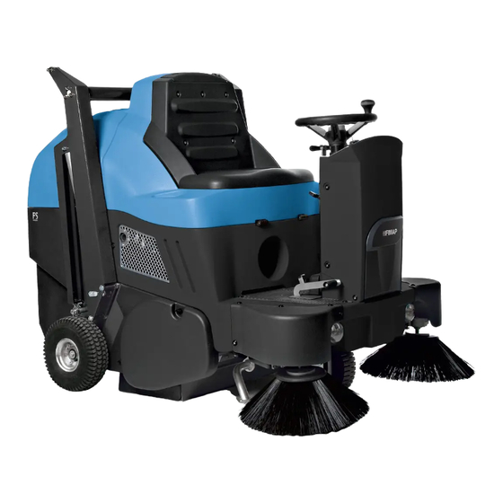
FS700 H
Use and maintenance manual
Fimap FS700 H Use And Maintenance Manual
Hide thumbs
1
2
Table Of Contents
3
4
5
6
7
8
9
10
11
12
13
14
15
16
17
18
19
20
21
22
23
24
25
26
27
28
29
30
31
32
33
34
35
36
37
38
39
40
page
of
40
Go
/
40
Contents
Table of Contents
Troubleshooting
Bookmarks
Table of Contents
Table of Contents
On Consignment of the Machine
Introductory Comment
Identification Data
Technical Description
Intended Use
Serial Number Plate
Symbols Used on the Machine
General Safety Regulations
Machine Preparation
Handling of the Packed Machine
How to Unpack the Machine
How to Move the Machine
Instrument Panel Components
Steering Column Components
Footboard Front-Right Components
Footboard Front-Left Components
Footboard Rear Components
Side Components of the Machine
Rear Components of the Machine
Front Machine Components
Type of Starter Battery
Maintenance and Disposal of the Starter Battery
Working Forward Speed
Reverse Function
Checking the Endothermic Engine
Checking the Level in the Hydraulic Oil Tank
Side Brush Assembly
Service Brake and Parking Brake
Blinking Light (Optional)
Filling the Fuel Tank
Work
Preparing to Work
Emptying the Debris Hopper (Manual Movement)
Emptying the Debris Hopper (Automatic Movement)
At the End of the Work
At the End of the Work (Versions with Manual Emptying of the Debris Hopper)
At the End of the Work (Versions with Automatic Emptying of the Debris Hopper)
Daily Maintenance
Cleaning the Central Brush
Cleaning the Side Brush
Weekly Maintenance
Cleaning the Panel Filter (Fp Versions)
Cleaning the Fabric Filter (Fs Versions)
Cleaning the Debris Hopper (Versions with Manual Emptying of the Debris Hopper)
Cleaning the Debris Hopper (Versions with Automatic Emptying of the Debris Hopper)
Side Brush Adjustment
Checking the Motor Oil Level
Maintaining the Hydraulic Oil Level
Extraordinary Maintenance
Central Brush Replacement
Side Brush Replacement
Troubleshooting
The Machine Does Not Start
The Endothermic Engine Does Not Start
The Machine Does Not Clean Well
The Machine Lifts Dust During Operation
Excessive or Altered Noise of the Central Brush
Excessive or Altered Noise of the Side Brush
Moving the Machine When the Motor Is Switched off
Disposal
Choosing and Using the Brushes
Ec Declaration of Conformity
Ec Declaration of Conformity
Advertisement
Quick Links
Download this manual
USE AND MAINTENANCE MANUAL
FS700 H
FS800 H
ED. 11-2012
ORIGINAL
INSTRUCTIONS
Doc. 10032019
AC
Version
EN
Table of
Contents
Previous
Page
Next
Page
1
2
3
4
5
Advertisement
Table of Contents
Need help?
Do you have a question about the FS700 H and is the answer not in the manual?
Ask a question
Questions and answers
Related Manuals for Fimap FS700 H
Floor Machine Fimap FSR Workshop Handbook
(93 pages)
Floor Machine Fimap FM43 F Use And Maintenance Manual
(21 pages)
Floor Machine Fimap FS80 B Use And Maintenance Manual
(31 pages)
Floor Machine Fimap FS120 B Use And Maintenance Manual
(31 pages)
Floor Machine Fimap FS120 D Use And Maintenance Manual
(31 pages)
Floor Machine Fimap FS800 H Use And Maintenance Manual
(40 pages)
Floor Machine Fimap FSR B Use And Maintenance Manual
(48 pages)
Floor Machine Fimap FSR HYBRID Use And Maintenance Manual
(48 pages)
Floor Machine Fimap FM33 Use And Maintenance Manual
Professional single disc machines (84 pages)
Floor Machine Fimap FM43 ORBITALE Manual
Extra spray (56 pages)
Floor Machine Fimap FM1500 S Use And Maintenance Manual
(16 pages)
Floor Machine Fimap FM1500 V Use And Maintenance Manual
(16 pages)
Floor Machine Fimap FS50 B-BT Use And Maintenance Manual
(24 pages)
Floor Machine Fimap FS50 B Use And Maintenance Manual
(21 pages)
Floor Machine Fimap FM4017 Use And Maintenance Manual
(21 pages)
Floor Machine Fimap FM43 ORB Use And Maintenance Manual
Professional single disc machines (84 pages)
This manual is also suitable for:
Fs800 h
Table of Contents
Print
Rename the bookmark
Delete bookmark?
Delete from my manuals?
Login
Sign In
OR
Sign in with Facebook
Sign in with Google
Upload manual
Upload from disk
Upload from URL


Need help?
Do you have a question about the FS700 H and is the answer not in the manual?
Questions and answers