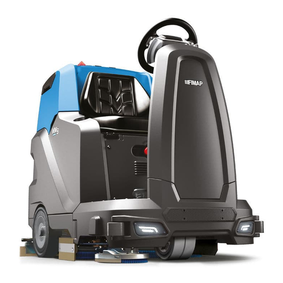
Fimap MMG Inspection Manual
Hide thumbs
Also See for MMG:
- Use and maintenance manual (28 pages) ,
- Use and maintenance manual (44 pages) ,
- Configuring manual (12 pages)
Advertisement
Quick Links
READ THE USE AND MAINTENANCE MANUAL
CONSOLE CONFIGURATIONS AND SETTINGS
Console Services
The console allows you to:
Program the chopper card to ensure the correct behaviour of the machine;
-
Test the electric components and circuit regarding the traction system.
-
Read the alarms to identify the error code easily.
-
Console use
The correct sequence to connect the console is:
1. TURN OFF the machine by turning the main key.
2. Connect the console to the chopper card via the connector on the board.
3. Turn on the machine and operate with the console.
4. When finish TURN OFF the machine.
5. Disconnect the console from the machine.
A BAD SEQUENCE IN CONNECTING AND UNCONNECTING THE CONSOLE CAN EASILY
ADJUSTMENT
AND
INSPECTIONS
DAMAGE THE CARD OR THE CONSOLE.
Doc.
Emesso Aprile 2010
MMG
Ver.
Pag.
10023983
AA
1 di 15
Advertisement

Summary of Contents for Fimap MMG
- Page 1 Doc. 10023983 ADJUSTMENT Emesso Aprile 2010 Ver. INSPECTIONS Pag. 1 di 15 READ THE USE AND MAINTENANCE MANUAL CONSOLE CONFIGURATIONS AND SETTINGS Console Services The console allows you to: Program the chopper card to ensure the correct behaviour of the machine; Test the electric components and circuit regarding the traction system.
-
Page 2: Alarm Table
Doc. 10023983 ADJUSTMENT Emesso Aprile 2010 Ver. INSPECTIONS Pag. 2 di 15 ALARM TABLE Message Alarm What to do Put the potentiometer in idle position and ALARM A1 Forward micro-switch on verify that the forward micro-switch is in turning on. FW Switch ON open. - Page 3 Doc. 10023983 ADJUSTMENT Emesso Aprile 2010 Ver. INSPECTIONS Pag. 3 di 15 CHOPPER CARD CONFIGURATION Console Code: 431320 To enter the parameter list: 1. Press the “MODE” button. 2. The first parameter description will appear, pressing up or down it is possible to scroll the parameter list.
- Page 4 Doc. 10023983 ADJUSTMENT Emesso Aprile 2010 Ver. INSPECTIONS Pag. 4 di 15 PARAMETERS: PARAMETER DEFAULT DISABLE DISABLE RESET TO DEFAULT ACCELERATION RAMP REVERSE RAMP NEUTRAL RAMP FORWARD SPEED BACKWARD SPEED MINIMUM SPEED BATTERY VOLTAGE SPEED REFERENCE single-ended single-ended REF. DEADBAND 50mV BRAKE DELAY MULTIMODE SPEED...
-
Page 5: Potentiometer Settings
Doc. 10023983 ADJUSTMENT Emesso Aprile 2010 Ver. INSPECTIONS Pag. 5 di 15 POTENTIOMETER SETTINGS (Resister Settings) 1) Ensure the machine is TURNED OFF. 2) Connect the console to the machine. 3) Turn on the machine. 4) Enter into the parameter list using the “MODE” button. 5) Scroll down the list until you reach the parameter “Speed reference appears”... - Page 6 Doc. 10023983 ADJUSTMENT Emesso Aprile 2010 Ver. INSPECTIONS Pag. 6 di 15 Electric installation tests 1. Check electric installation functionality: switches, contactors, motors, solenoid valve, power fuses and thermal switches. 2. Check the functionality and the potentiometer conditions and the conditions of the direction micro-switches. 3.
- Page 7 Doc. 10023983 ADJUSTMENT Emesso Aprile 2010 Ver. INSPECTIONS Pag. 7 di 15 Actuators pcb control English Version TBA...
- Page 8 Doc. 10023983 ADJUSTMENT Emesso Aprile 2010 Ver. INSPECTIONS Pag. 8 di 15 Battery check card adjustment 1. Check that when turning on the machine the battery check card has the following starting sequence: Turning on of the LED which correspond to the set-up (red LED = “0”).
- Page 9 Doc. 10023983 ADJUSTMENT Emesso Aprile 2010 Ver. INSPECTIONS Pag. 9 di 15 2. To adjust the battery charger act as follow: Lift up the sticker on the front part of the battery charger. Set up the dip switches under the sticker following the instructions of the table below.
- Page 10 Doc. 10023983 ADJUSTMENT Emesso Aprile 2010 Ver. INSPECTIONS Pag. 10 di 15 Clean water installation testing 3. Check the cleanliness and functionality of the solution filter under the solution tank plug. 4. Check the cleanness and sealing of the solution filter.
- Page 11 Doc. 10023983 ADJUSTMENT Emesso Aprile 2010 Ver. INSPECTIONS Pag. 11 di 15 2. Loosen the locking nut and unscrew the screw until the traction wheel is secure. Once you have reached the right adjustment adjust the locking nut. 3. Check that when the lever is in standard position (brake off) the wheel is free to move.
- Page 12 Doc. 10023983 ADJUSTMENT Emesso Aprile 2010 Ver. INSPECTIONS Pag. 12 di 15 Scrubbing deck adjustment 1. The brush deck is on a floating support. It is necessary to adjust its horizontal inclination only. 2. To proceed to the deck adjustmet proceed as follow: ...
- Page 13 Doc. 10023983 ADJUSTMENT Emesso Aprile 2010 Ver. INSPECTIONS Pag. 13 di 15 Verify the cleanness and conditions of the detergent hoses and detergent tank. Check the correct functioning of the dosing system bypass valve. The bypass system can be actuated by a valve installed on the brush deck.
- Page 14 Doc. 10023983 ADJUSTMENT Emesso Aprile 2010 Ver. INSPECTIONS Pag. 14 di 15 Squeegee adjusmtent 1. Adjust the adjuster for the blade inclination when the vacuum motor is on. The blade has to have an even inclination on all its lengths. 2.
- Page 15 Doc. 10023983 ADJUSTMENT Emesso Aprile 2010 Ver. INSPECTIONS Pag. 15 di 15 Functional check of the machine Check the functionality of switches and warning lamps; Check the functionality of the accelerator lever; Check the functionality of the brush base; ...


Need help?
Do you have a question about the MMG and is the answer not in the manual?
Questions and answers
ERROR CODE ALL --91