Sun Oracle Netra SPARC T3-1 Installation Manual
Hide thumbs
Also See for Netra SPARC T3-1:
- Installation manual (76 pages) ,
- Getting started manual (7 pages)
Table of Contents
Advertisement
Quick Links
Advertisement
Table of Contents

Related Manuals for Sun Oracle Netra SPARC T3-1


Summary of Contents for Sun Oracle Netra SPARC T3-1
-
Page 1: Installation Guide
Netra SPARC T3-1 Server Installation Guide Part No.: E20690-02 August 2013... - Page 2 Corporation and its affiliates are not responsible for and expressly disclaim all warranties of any kind with respect to third-party content, products, and services. Oracle Corporation and its affiliates will not be responsible for any loss, costs, or damages incurred due to your access to or use of third-party content, products, or services.
-
Page 3: Table Of Contents
Contents Using This Documentation vii Preparing for Installation 1 Installation Task Overview 1 Server Overview 2 Confirming Server Specifications 5 Physical Specifications 5 Minimum Clearance for Service Access 6 Electrical Specifications 6 Input Power Information 7 Overcurrent Protection Requirements 8 DC Power Source, Power Connection, and Grounding Requirements 8 AC and DC Server Environmental Requirements 10 Acoustic Noise Emissions 10... - Page 4 Connect the NET MGT Cable 68 ▼ Connect the Ethernet Network Cables 69 ▼ Connect Other Data Cables 69 ▼ Prepare the Power Cords 70 Assembling and Connecting DC Power Cords 71 Netra SPARC T3-1 Server Installation Guide • August 2013...
- Page 5 Connect the DC Input Power Cords to the Server 74 Powering On the Server for the First Time 77 Power On Task Overview 77 Oracle ILOM System Console Overview 78 ▼ Connect a Terminal or Emulator to the SER MGT Port 79 ▼...
- Page 6 Netra SPARC T3-1 Server Installation Guide • August 2013...
-
Page 7: Using This Documentation
Oracle’s Netra SPARC T3-1 server. “Related Documentation” on page vii ■ “Documentation, Support, and Training” on page viii ■ Related Documentation The Netra SPARC T3-1 server documents listed as online are available at: http://www.oracle.com/pls/topic/lookup?ctx=E20689-01&id=homepage Application Title Format Location... - Page 8 The Oracle Integrated Lights Out Manager (ILOM) 3.0 documentation is online at: http://www.oracle.com/pls/topic/lookup?ctx=ilom30&id=homepage Application Title Location Late-breaking news Oracle Integrated Lights Out Manager (ILOM) 3.0 Features Updates and Release Online and issues Notes Installation and Oracle Integrated Lights Out Manager (ILOM) 3.0 Getting Started Guide...
-
Page 9: Preparing For Installation
Preparing for Installation These topics provide background information needed to install the Netra SPARC T3-1 server. “Installation Task Overview” on page 1 ■ “Server Overview” on page 2 ■ “Confirming Server Specifications” on page 5 ■ “Shipping Kit Inventory List” on page 12 ■... -
Page 10: Server Overview
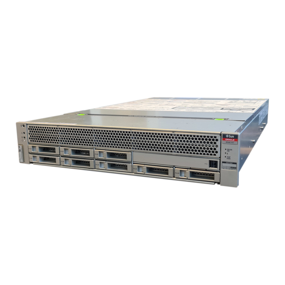
This topic describes the main components and capabilities of the server. The first illustration shows the server with the air filter. The second illustration shows the server without the air filter. Netra SPARC T3-1 Server Installation Guide • August 2013... - Page 11 Preparing for Installation...
- Page 12 Removable mass storage Four SFF (2.5 in.) SAS drives One SATA DVD drive Service processor ASPEED AST2200 BMC running Oracle ILOM 3.x. service processor firmware with provision for: • 2D graphics (HD-15 VGA Connector) • 128 MB SDRAM • Serial management (RJ-45) •...
-
Page 13: Confirming Server Specifications
Related Information “Confirming Server Specifications” on page 5 ■ “Installation Task Overview” on page 1 ■ Confirming Server Specifications Prior to installing the server, review the server specifications and prepare the installation site. “Physical Specifications” on page 5 ■ “Electrical Specifications” on page 6 ■... -
Page 14: Minimum Clearance For Service Access
9.4 A @ 100 VAC or 4.7 A @ 200 VAC 19.58 A -48 VDC (940 VA) (940 VA) Frequency (nominal) 50/60 Hz (47 to 63 Hz range) DC input treatment Isolated DC Return (DC-I) Netra SPARC T3-1 Server Installation Guide • August 2013... -
Page 15: Input Power Information
2000 volts. You can, however, install a surge protector if your site requires an additional protector. Caution – Safety agency requirements prohibit Oracle Corporation from changing a product from AC input to DC input or from DC input to AC input after the product has been removed from the agency approved manufacturing site. -
Page 16: Overcurrent Protection Requirements
“DC Power Source, Power Connection, and Grounding Requirements” on page 8 ■ DC Power Source, Power Connection, and Grounding Requirements The server power source and connections must meet the following requirements: Netra SPARC T3-1 Server Installation Guide • August 2013... - Page 17 Caution – The DC power source must be reliably grounded. The server chassis must be grounded with the power supply ground pins or with the chassis ground studs. It is acceptable to have both grounds connected. Note – The DC version of the server must be installed in a restricted-access location. According to the intent of the U.S.
-
Page 18: Ac And Dc Server Environmental Requirements
“Acoustic Noise Emissions” on page 10 ■ “Cooling Zones and Airflow Clearance” on page 11 ■ Acoustic Noise Emissions The declared noise emissions for the server are in accordance with ISO 9296 standards. Netra SPARC T3-1 Server Installation Guide • August 2013... -
Page 19: Cooling Zones And Airflow Clearance
70.8 dBA (AC server) 70.8 dBA (DC server) Related Information Netra SPARC T3-1 Server Safety and Compliance Guide ■ Cooling Zones and Airflow Clearance Note – Proper airflow into and out of the server is essential for keeping the server’s internal temperatures within a safe operating range. -
Page 20: Shipping Kit Inventory List
■ RJ-45 to DB-25 analog to digital video adapter ■ Antistatic wrist strap ■ 19-inch, 4-post rackmount kit ■ Netra Rack Server Getting Started Guide with license and safety documents ■ Netra SPARC T3-1 Server Installation Guide • August 2013... -
Page 21: Front Panel Components
Optional components (for example, PCIe cards) that are packaged separately from ■ the other items unless they are installed at the factory as part of the system. Related Information “Server Handling Precautions” on page 15 ■ “ESD Precautions” on page 16 ■... -
Page 22: Back Panel Components
“Back Panel Components” on page 14 ■ Back Panel Components Power supplies (PS1 - PS0 top to Service LEDs:- Locator LED/Locator bottom) (AC supplies shown) button (white)- Service Action Required LED (amber)- Main Power/OK LED (green) Netra SPARC T3-1 Server Installation Guide • August 2013... -
Page 23: Server Handling Precautions
Power supply status LEDs: - OK SER MGT RJ-45 serial port (output): (green) - Service Action Required: (amber) - AC or DC (input power): (green) Alarm port NET MGT RJ-45 network port Expansion slot 0 (PCIe 2.0 x8 or XAUI) Network 10/100/1000 ports (NET0 to NET3) for host Expansion slot 3 (PCIe 2.0 x8) -
Page 24: Esd Precautions
To install the system, you must have the following tools: No. 2 Phillips screwdriver ■ ESD mat and grounding strap ■ In addition, you must provide a system console device, such as one of the following: ASCII terminal ■ Netra SPARC T3-1 Server Installation Guide • August 2013... -
Page 25: Optional Component Installation
Optional components (for example, PCIe cards) ordered as part of the system are installed in the server at the factory. If you ordered any options that are not factory-installed, see Netra SPARC T3-1 Server Service Manual and the component’s documentation for installation instructions. - Page 26 Netra SPARC T3-1 Server Installation Guide • August 2013...
-
Page 27: Installing The Server
Installing the Server These topics describe how to install the server into an equipment rack using a rackmount kit. Note – In this guide, the term rack means either an open rack or a closed cabinet. “Rack Compatibility” on page 19 ■... -
Page 28: Rack Cautions
Caution – Mechanical Loading. Mount the equipment in the rack so that the weight is distributed evenly. A hazardous condition can exist with uneven mechanical loading. Netra SPARC T3-1 Server Installation Guide • August 2013... -
Page 29: Stabilize The Rack For Installation
Caution – Circuit Overloading. Do not overload the power supply circuits. Before connecting the server to the supply circuit, review the equipment nameplate power ratings and consider the effect that circuit overloading might have on overcurrent protection and supply wiring. Caution –... -
Page 30: Mounting The Server Into A 4-Post Rack
“600-mm, 4-Post Hardmount Rackmount Kit” on 600 mm x 600 mm rackmount kit. page 34 “Install the Server (600-mm, 4-Post Hardmount Rackmount Kit)” on page 35 Related Information “Preparing for Installation” on page 1 ■ Netra SPARC T3-1 Server Installation Guide • August 2013... -
Page 31: 19-Inch, 4-Post Hardmount Rackmount Kit
“Rack Cautions” on page 20 ■ “Stabilize the Rack for Installation” on page 21 ■ 19-Inch, 4-Post Hardmount Rackmount Kit Rear mount flanges (2) Rear mount support brackets (2) Screws (see following table) Hardmount brackets (2) Installing the Server... -
Page 32: Install The Server (19-Inch, 4-Post Hardmount Rackmount Kit)
1. Read the Cautions for racks. “Rack Cautions” on page 2. Use four of the supplied M5 x 4.5-mm flathead Phillips screws to secure each of the hardmount brackets to the sides of the server. Netra SPARC T3-1 Server Installation Guide • August 2013... - Page 33 3. Measure the depth of the rack. 4. Install the rear mount support brackets at the rear of the server, extending the rear mount support brackets to the measured depth of the rack. Use two to three of the supplied M4 x 0.5 x 5 mm panhead Phillips screws for each bracket, depending on the rack depth.
- Page 34 8. Using two screws for each rear mount support bracket, secure the rear mount support brackets to the rear of the rack. Related Information “Stabilize the Rack for Installation” on page 21 ■ “19-Inch, 4-Post Hardmount Rackmount Kit” on page 23 ■ Netra SPARC T3-1 Server Installation Guide • August 2013...
-
Page 35: 19-Inch, 4-Post Sliding Rail Rackmount Kit
19-Inch, 4-Post Sliding Rail Rackmount Kit After installing the server using this optional 19-inch, 4-post sliding rail rackmount kit, you can extend the server out of the rack for servicing. You also need the hardmount brackets from the standard rackmount kit that came with the server. -
Page 36: Install The Server (19-Inch, 4-Post Sliding Rail Rackmount Kit)
These hardmount brackets and screws are shipped with the standard server ship kit, not as part of the sliding rail 19-inch, 4-post rackmount kit. Netra SPARC T3-1 Server Installation Guide • August 2013... - Page 37 3. Press in the button on each slide assembly and pull the glide completely out of the slide. Glide Slide (in two parts) Installing the Server...
- Page 38 To secure each bracket, use two of the brass M6 collar screws and M6 cage nuts (if required) and one threaded strip, exactly as you did for the front rack uprights in the previous step. Netra SPARC T3-1 Server Installation Guide • August 2013...
- Page 39 Note – If your rack has 10–32 holes, use the 10–32 collar screws and 10–32 threaded strips. 7. Extend a slide to line up the access holes with the front screw holes. 8. Secure the slide onto the short and long brackets at the front and rear of the rack.
- Page 40 12. Push in the slide buttons and slide the server all the way into the rack enclosure. Netra SPARC T3-1 Server Installation Guide • August 2013...
- Page 41 13. Using two screws per side, secure the front of the hardmount brackets that are attached to the sides of the server to the front of the rack. The size of the screws varies, depending on your particular rack. Related Information “Stabilize the Rack for Installation”...
-
Page 42: 600-Mm, 4-Post Hardmount Rackmount Kit
“19-Inch, 4-Post Sliding Rail Rackmount Kit” on page 27 ■ 600-mm, 4-Post Hardmount Rackmount Kit Adjustable rails (2) Side rails (2) Screws (see following table) Rear flanges (2) Netra SPARC T3-1 Server Installation Guide • August 2013... -
Page 43: Install The Server (600-Mm, 4-Post Hardmount Rackmount Kit)
600-mm, 4-Post Hardmount Screw Kit Contents TABLE: Description Where Used M5 x 7 SEM screws 8 for side rails, 4 for rear flanges M5 x 12.7 mm screws 10 for rack, if appropriate M6 x 13 mm screws 10 for rack, if appropriate M6 square clip nuts 9 for rack, if appropriate 10-32 x 0.5 in. - Page 44 3. Lift one of the adjustable rails to the desired location in the rack. Using two screws, secure the front of the rail in the rack. The size of the screws varies, depending on your particular rack. Netra SPARC T3-1 Server Installation Guide • August 2013...
- Page 45 4. At the rear of the rack, use two screws to secure the rear of the adjustable rails to the rack. The size of the screws varies, depending on your particular rack. 5. Tighten the two screws at the middle of each adjustable rail. 6.
- Page 46 The side rails can accommodate rack rail setbacks (the distance from the front of the rack to the rack rail) of 50 mm, 75 mm, or 100 mm, depending on the type of rack you are installing the server into. Netra SPARC T3-1 Server Installation Guide • August 2013...
- Page 47 9. Lift the server into the rack and slide the server onto the adjustable rails. Installing the Server...
- Page 48 14. Push the server backward until it rests flush against the rear flanges, then use one M5 x 7 SEM screw for each rear flange to secure the rear of the server to the rear flanges. Netra SPARC T3-1 Server Installation Guide • August 2013...
- Page 49 15. At the front of the rack, use two screws per side to secure the side rails that are attached to the server to the front of the rack. The size of the screws varies, depending on your particular rack. Installing the Server...
-
Page 50: Mounting The Server Into A 2-Post Rack
The server ships with a 19-inch, 4-post hardmount rackmount kit, but you can order optional rackmount kits for 2-post racks. Note – References to left and right are from your viewpoint as you face either the front or rear of the equipment. Netra SPARC T3-1 Server Installation Guide • August 2013... - Page 51 Caution – The server is heavy. Two people are required to lift and mount the server into a rack enclosure when following these procedures. Caution – You must install the server into a rack following these instructions. If you deviate from these instructions when installing the server, your installation will not be supported.
-
Page 52: 23-Inch, 2-Post Hardmount Rackmount Kit
M6 square clip nuts 9 for rack, if appropriate 10-32 x 0.5 in. combo head screws 12 for rack, if appropriate 12-24 x 0.5 in. combo head screws 12 for rack, if appropriate Netra SPARC T3-1 Server Installation Guide • August 2013... -
Page 53: Install The Server (23-Inch, 2-Post Hardmount Rackmount Kit)
Related Information “Install the Server (23-Inch, 2-Post Hardmount Rackmount Kit)” on page 45 ■ ▼ Install the Server (23-Inch, 2-Post Hardmount Rackmount Kit) Note – The 23-inch, 2-post rackmount kit supports rack web thicknesses (the width of the rack post) of 76.20 mm (3 in.), 101.6 mm (4 in.), and 127 mm (5 in.). 1. - Page 54 4. Lift the server into the rack, and slide the server onto the rail guides. Netra SPARC T3-1 Server Installation Guide • August 2013...
- Page 55 5. Using two screws on each side, secure each side bracket on the server to the front of the rack. The size of the screws varies, depending on your particular rack. 6. (Optional) If your environment contains especially high vibrations, install the rear plates to further secure the server to the rack.
- Page 56 Slide the rear plate in so that the screw slides into position into one of the eyelets. The screw head should be facing the rear of the server. The other side of the rear plate should be in front of the rack post. Netra SPARC T3-1 Server Installation Guide • August 2013...
- Page 57 c. Tighten the screw to secure the rear plate to the eyelet on the side bracket. d. Using two screws, secure the other side of the rear plate to the back of the post. The size of the screws varies, depending on your rack. e.
-
Page 58: 19-Inch, 2-Post Hardmount Rackmount Kit
19-Inch, 2-Post Hardmount Rackmount Kit Rear plates (2) Screws (see following table) Side brackets (2) Netra SPARC T3-1 Server Installation Guide • August 2013... -
Page 59: Install The Server (19-Inch, 2-Post Hardmount Rackmount Kit)
19-Inch, 2-Post Hardmount Rack Screw Kit Contents TABLE: Description Where Used M5 x 7 SEM screws 8 for side brackets, 2 extra M3 x 8 SEM screws 4 for rear plates, 2 extra M5 x 12.7 mm screws 10 for rack, if appropriate M6 x 13 mm screws 10 for rack, if appropriate M6 square clip nuts... - Page 60 3. Lift the server into the rack. 4. Using two screws for each bracket, secure the front of the server to the front of the rack. The size of the screws varies, depending on your rack. Netra SPARC T3-1 Server Installation Guide • August 2013...
- Page 61 5. (Optional) If your environment contains especially high vibrations, install the rear plates to further secure the server to the rack. The rear plates attach to the rear of the post and to one of the three sets of eyelets on each side bracket, depending on the thickness of the post.
- Page 62 The screw heads should be facing the rear of the server. The other side of the rear plate should be in front of the rack post. c. Tighten the screws to secure the rear plate to the set of eyelets on the side bracket. Netra SPARC T3-1 Server Installation Guide • August 2013...
- Page 63 d. Using two screws, secure the other side of the rear plate to the back of the post. The size of the screws varies, depending on your rack. e. Secure the rear plate on the other post. Repeat Step a through Step Related Information...
-
Page 64: 19-Inch, 2-Post Rack Sliding Rail Rackmount Kit
19-Inch, 2-Post Rack Sliding Rail Rackmount Kit Slide assemblies (2) Cable management arm Inside glides (2) Threaded strips – M6 (4) 10-32 (4) (not pictured) Screws (see following table) Netra SPARC T3-1 Server Installation Guide • August 2013... -
Page 65: Install A Server (19-Inch, 2-Post Sliding Rail Rackmount Kit)
19-Inch, 2-Post Sliding Rail Mount Screw Kit Contents TABLE: Description Where Used M4 x 0.5 mm x 5 mm Phillips panhead 8 for glides, 2 extra screws M5 x 12.7 mm screws 10 for rack, if appropriate M6 x 13 mm screws 10 for rack, 2 extra M6 square clip nuts 9 for rack, if appropriate... - Page 66 3. Using eight of the M4 x 0.5 x 5 mm Phillips panhead screws from the rackmount kit (four for each side), attach each glide to the side of the server chassis. Netra SPARC T3-1 Server Installation Guide • August 2013...
- Page 67 4. Lift each front bracket to the desired position at the front of the rack and attach a front bracket to each of the front rack posts. To secure each bracket, use two of the M5 x 12.7 mm screws or two of the M6 x 13 mm screws.
- Page 68 5), move the brackets inward or outward to the appropriate points, then tighten the brackets again. 7. Push in the slide buttons and slide the server all the way into the rack enclosure. Netra SPARC T3-1 Server Installation Guide • August 2013...
- Page 69 8. Fully tighten the screws on the front brackets. 9. Fully tighten the screws on the rear brackets. Installing the Server...
- Page 70 There are labels on both the rails and the CMA. The CMA side that has an arrow attaches to the right inner glide. The other side of the CMA attaches to the outer member. Netra SPARC T3-1 Server Installation Guide • August 2013...
- Page 71 11. Attach the CMA to the left rail. There are labels on both the rails and the CMA. The CMA side that has an arrow attaches to the left inner glide. The other side of the CMA attaches to the outer member.
- Page 72 Related Information “Stabilize the Rack for Installation” on page 21 ■ “19-Inch, 2-Post Rack Sliding Rail Rackmount Kit” on page 56 ■ Netra SPARC T3-1 Server Installation Guide • August 2013...
-
Page 73: Connecting The Server Cables
Connecting the Server Cables Connect and configure the network and serial ports before you attempt to boot the server. “Cabling Requirements” on page 65 ■ “Back Panel Connectors and Ports” on page 66 ■ “Connect the SER MGT Cable” on page 67 ■... -
Page 74: Back Panel Connectors And Ports
Note - Using the ILOM sideband management feature, you can access the SP using one of these ports. Refer to Netra SPARC T3-1 Server Administration Guide for instructions. Netra SPARC T3-1 Server Installation Guide • August 2013... -
Page 75: Connect The Ser Mgt Cable
Connectors and Ports Description USB ports (USB 0, USB 1) The two USB ports support hot-plugging. You can connect and disconnect USB cables and peripheral devices while the server is running, without affecting server operations. Note - The maximum USB cable length for connecting to the server’s USB ports is 5 mm. -
Page 76: Connect The Net Mgt Cable
Related Information “Connect the Ethernet Network Cables” on page 69 ■ “Connect the SER MGT Cable” on page 67 ■ “Connect Other Data Cables” on page 69 ■ Netra SPARC T3-1 Server Installation Guide • August 2013... -
Page 77: Connect The Ethernet Network Cables
10 Mbps, 100 Mbps, and 1000 Mbps. Note – The ILOM sideband management feature enables you to access the SP using one of these Ethernet ports. Refer to Netra SPARC T3-1 Server Administration Guide for instructions. 1. Connect a Category 5 (or better) cable from your network switch or hub to Ethernet Port 0 (NET0) on the rear of the chassis. -
Page 78: Prepare The Power Cords
DC power present. 2. Route the power cords from the power source to the rear of the server and secure the cables with nylon tie wraps. Related Information AC power source documentation ■ Netra SPARC T3-1 Server Installation Guide • August 2013... -
Page 79: Assembling And Connecting Dc Power Cords
Assembling and Connecting DC Power Cords These topics provide the power requirements for the DC-powered version of the server, as well as instructions on how to assemble and connect DC power cords to the server. Description Link Review requirements for the DC power “Electrical Specifications”... - Page 80 3. Locate the three wires coming from your DC power source that will be used in the connection to your unit: -48V or -60V (negative terminal) ■ Chassis ground ■ -48V or -60V Return (positive terminal) ■ Netra SPARC T3-1 Server Installation Guide • August 2013...
- Page 81 Note – Depending on the DC power source, the -48V or -60V (negative terminal) might be marked with a minus (-) symbol. The -48V or -60V Return (positive terminal) might be marked with a positive (+) symbol. 4. Strip 1/2 in. (13 mm) of insulation from each of the wires coming from the DC power source.
-
Page 82: Connect The Dc Input Power Cords To The Server
“Connect the DC Input Power Cords to the Server” on page 74 ■ ▼ Connect the DC Input Power Cords to the Server 1. Ensure that the circuit breaker to your power source is turned off. Netra SPARC T3-1 Server Installation Guide • August 2013... - Page 83 Caution – Before proceeding with these instructions, turn off the power from the DC power source through the circuit breakers. 2. Route the power cables in the rack and secure the cables with nylon tie wraps. 3. Connect the chassis ground wire to the facility ground and ensure that this connection has proper bonding.
- Page 84 Netra SPARC T3-1 Server Installation Guide • August 2013...
-
Page 85: Powering On The Server For The First Time
Powering On the Server for the First Time These topics include instructions for powering on the server for the first time, booting the server, and configuring the Oracle Solaris OS. “Power On Task Overview” on page 77 ■ “Oracle ILOM System Console Overview” on page 78 ■... -
Page 86: Oracle Ilom System Console Overview
Oracle ILOM System Console Overview When you power on the server, the boot process begins under the control of the Oracle ILOM system console. The ILOM system console displays status and error messages generated by firmware-based tests during server startup. -
Page 87: Connect A Terminal Or Emulator To The Ser Mgt Port
▼ Connect a Terminal or Emulator to the SER MGT Port ● Connect a terminal or a terminal emulator (PC or workstation) to the service processor serial management port. Configure the terminal or terminal emulator with these settings: 9600 baud ■... - Page 88 5. Open a second terminal device, log in to the SP as root with a password of changeme. After a brief delay, the SP prompt is displayed (->). At this point, there are many commands you can perform using the ILOM interface. Netra SPARC T3-1 Server Installation Guide • August 2013...
- Page 89 You are prompted to confirm the configuration several times, enabling confirmation and changes. If you are not sure how to respond to a particular value, you can accept the default, and make future changes when the Oracle Solaris OS is running. See “Oracle Solaris OS Configuration Parameters”...
-
Page 90: Oracle Solaris Os Configuration Parameters
Oracle Solaris OS Configuration Parameters You must provide these parameters during initial Oracle Solaris OS configuration. Parameter Description Language Select a number from the displayed language list. Locale Select a number from the displayed locale list. Terminal Type Select a terminal type that corresponds with your terminal device. -
Page 91: Assigning A Static Ip Address To The Service Processor
Accept the default date and time or change the values. root Password Type the root password twice. This password is for the superuser account for the Oracle Solaris OS on this server. This password is not the SP password. Related Information “Back Panel Connectors and Ports” on page 66 ■... - Page 92 2. Enter root for the login name followed by your password. ORACLESP-xxxxxxxxxx login: root Password: password (nothing displayed) Oracle(R) Integrated Lights Out Manager Version 3.0.12.x.x rxxxxx Copyright (c) 2010, Oracle and/or its affiliates. All rights reserved. -> Netra SPARC T3-1 Server Installation Guide • August 2013...
- Page 93 In this procedure, you connect to the SER MGT port to manually reconfigure the NET MGT port to use a static IP address. Note – For more information on configuring ILOM, refer to Netra SPARC T3-1 Server Administration Guide. 1. Set these network parameters according to the specific details of your network configuration.
- Page 94 3. Verify that the parameters were set correctly. The following example shows parameters that have been set to convert a service processor from a DHCP configuration to a static configuration. -> show /SP/network /SP/network Targets: interconnect ipv6 test Netra SPARC T3-1 Server Installation Guide • August 2013...
- Page 95 Properties: commitpending = (Cannot show property) dhcp_server_ip = xxx.xxx.xxx.xxx ipaddress = xxx.xxx.xxx.xxx ipdiscovery = dhcp ipgateway = xxx.xxx.xxx.xxx ipnetmask = 255.255.252.0 macaddress = 00:14:4F:3F:8C:AF managementport = /SYS/MB/SP/NETMGMT outofbandmacaddress = 00:14:4F:E8:3D:6F pendingipaddress = xxx.xxx.xxx.xxx pendingipdiscovery = static pendingipgateway = xxx.xxx.xxx.xxx pendingipnetmask = 255.255.255.0 pendingmanagementport = /SYS/MB/SP/NETMGMT sidebandmacaddress = 00:14:4F:E8:3D:6E state = enabled...
- Page 96 Netra SPARC T3-1 Server Installation Guide • August 2013...
-
Page 97: Identifying The Server Ports
Identifying the Server Ports These topics provide the pin descriptions of the server ports. “USB Ports” on page 89 ■ “Alarm Port” on page 90 ■ “SER MGT Port” on page 91 ■ “NET MGT Port” on page 91 ■ “Gigabit-Ethernet Ports”... -
Page 98: Alarm Port
Each alarm has a corresponding alarm LED on the front panel: ALARM0 and the Critical LED ■ ALARM1 and the Major LED ■ ALARM2 and the Minor LED ■ ALARM3 and the User LED ■ Netra SPARC T3-1 Server Installation Guide • August 2013... -
Page 99: Ser Mgt Port
Related Information “Back Panel Connectors and Ports” on page 66 ■ “Front Panel Components” on page 13 ■ “Connect Other Data Cables” on page 69 ■ SER MGT Port The SER MGT RJ-45 port, located on the back panel, provides the default connection to the system console. -
Page 100: Gigabit-Ethernet Ports
Four RJ-45 Gigabit-Ethernet connectors (NET0, NET1, NET2, NET3) can be accessed from the back panel. The Ethernet interfaces operate at 10 Mbit/sec, 100 Mbit/sec, and 1000 Mbit/sec. Signal Description Signal Description Transmit/Receive Data 0 + Transmit/Receive Data 2 - Netra SPARC T3-1 Server Installation Guide • August 2013... -
Page 101: Video Port
Signal Description Signal Description Transmit/Receive Data 0 - Transmit/Receive Data 1 - Transmit/Receive Data 1 + Transmit/Receive Data 3 + Transmit/Receive Data 2 + Transmit/Receive Data 3 - Related Information “Back Panel Connectors and Ports” on page 66 ■ “Connect Other Data Cables” on page 69 ■... - Page 102 Related Information “Back Panel Connectors and Ports” on page 66 ■ “Connect Other Data Cables” on page 69 ■ Netra SPARC T3-1 Server Installation Guide • August 2013...
-
Page 103: Glossary
Glossary ACPI Advanced configuration and power interface. Automatic system recovery. American wire gauge. BIOS Basic input/output system. Baseboard management controller. Command-line interface. Cable management arm, used to route and secure cables extending from the rear of the system. Clear To Send. - Page 104 Dynamic Host Configuration Protocol. DIMM Dual in-line memory module. Dual-rank DIMM. Error correction code. Electromagnetic interference. Electrostatic discharge. GRUB GNU grand unified bootloader. An open source boot loader. Host bus adapter. Netra SPARC T3-1 Server Installation Guide • August 2013...
- Page 105 NEBS certification. NET MGT Network management port. After connecting a network cable to this NET MGT port, you can configure the system Oracle ILOM SP through this port. Network interface card. Network Time Protocol.
- Page 106 Solaris Operating System. The suite’s multiple hardware diagnostic tests verify the functionality of most hardware controllers and devices for SPARC and x86 architecture based systems. Oracle VTS 7.0 is the first version of this software and supersedes the SunVTS suites. Outside plant Operating system.
- Page 107 QSFP Quad small form-factor pluggable. RAID Redundant array of independent disks. Reliability, availability, and serviceability. Remote installation services. Rotations per minute. Request To Send. Serial-attached SCSI. SATA Serial advanced technology attachment. System configuration card. SCSI Small computer system interface. SER MGT Serial management port.
- Page 108 SunVTS Sun Validation Test Suite. SunVTS software runs through version 6.x. The SunVTS software is superseded by the Oracle VTS 7.0 software. Trusted Computing Group. Trusted platform module. For more information, refer to the Microsoft Windows Trusted Platform Module Management documentation.
-
Page 109: Index
Index Numerics ambient temperature, 10 19-inch, 2-post hardmount installing, 51 rackmount kit, 50 back panel screw kit, 51 ports and connectors, location, 66 19-inch, 2-post slide mount baud rate installing, 57 serial terminal, 79 rackmount kit, 56 bits setting for serial terminal, 79 screw kit, 57 booting 19-inch, 4-post hardmount... - Page 110 65 23-inch, 2-post hardmount, 45 modem not for use with the SER MGT port, 67 600-mm, 4-post hardmount, 34 stabilizing the rack, 21 relative humidity, 10 NEBS, 10 NET MGT port Netra SPARC T3-1 Server Installation Guide • August 2013...
- Page 111 SER MGT port location, 66 pinouts, 91 serial management port See SER MGT port serial terminal baud rate, 79 bit setting, 79 handshake, 79 parity, no, 79 settings, 79 stop bit, 79 service access, 6 clearance, 6 service processor accessing with serial management port, 83 powering on for the first time, 79 set commands, 85 set command, 85...
- Page 112 Netra SPARC T3-1 Server Installation Guide • August 2013...
Need help?
Do you have a question about the Netra SPARC T3-1 and is the answer not in the manual?
Questions and answers