Sun Oracle SPARC T5120 Installation Manual
Hide thumbs
Also See for SPARC T5120:
- Administration manual (70 pages) ,
- Getting started manual (6 pages)
Table of Contents
Advertisement
Quick Links
Download this manual
See also:
Administration Manual
Advertisement
Table of Contents

Related Manuals for Sun Oracle SPARC T5120


Summary of Contents for Sun Oracle SPARC T5120
- Page 1 Sun SPARC Enterprise T5120 and T5220 Servers Installation Guide Part No. 820-2178-14 October 2010, Revision A...
- Page 2 Copyright © 2009, 2010 Oracle and/or its affiliates. All rights reserved. FUJITSU LIMITED provided technical input and review on portions of this material. This software and related documentation are provided under a license agreement containing restrictions on use and disclosure and are protected by intellectual property laws.
-
Page 5: Table Of Contents
Contents Using This Documentation ix Preparing for Installation 1 Server Overview 1 Server Handling Precautions 3 Input Power Information and Precautions 3 Tools and Equipment Needed 4 Optional Component Installation 5 ESD Precautions 6 Installation Overview 6 Preparing for Installation 8 Installing the Hardware 8 Configuring the Service Processor 9 Configuring the Host Software 10... - Page 6 Installing the Cable Management Arm for Both Servers 30 ▼ Install the Cable Management Arm 31 ▼ Verify the Operation of the Slide Rails and the CMA 35 Connecting the Server Cables for Both Servers 37 Connect the Service Processor Serial Management Port 38 ▼...
- Page 7 ▼ Avoid Booting the Solaris Operating System at Startup 65 ▼ Reset the System 65 ▼ Power Cycle the System 66 Verifying System Functionality 67 Updating the Firmware 69 flashupdate command 69 ▼ Update the Firmware 70 Selecting a Boot Device 73 Selecting a Boot Device 73 ▼...
- Page 8 Assembling and Installing DC Power Cables for the Sun SPARC Enterprise T5220 Server 101 Requirements for Servers With DC Input Power 101 Input Power Restrictions 102 DC Supply and Ground Conductor Requirements 102 Overcurrent Protection Requirements 103 Assembling and Installing the DC Input Power Cables 103 ▼...
-
Page 9: Using This Documentation
Using This Documentation This document provides instructions, backgroud information, and reference material to help you install Oracle’s Sun SPARC Enterprise T5120 and T5220 servers. “UNIX Commands” on page ix ■ “Shell Prompts” on page x ■ “Related Documentation” on page x ■... -
Page 10: Related Documentation
Shell Prompts Shell Prompt C shell machine-name% C shell superuser machine-name# Bourne shell and Korn shell Bourne shell and Korn shell superuser Related Documentation The documents listed as online are available at: (http://docs.sun.com/app/docs/prod/sparc.t5120) (http://docs.sun.com/app/docs/prod/sparc.t5220) Part Application Title Number Format Location Product Notes SPARC Enterprise T5120 and T5220 Servers Product Notes 820-2176 PDF... -
Page 11: Documentation Feedback
Part Application Title Number Format Location Service SPARC Enterprise T5120 and T5220 Servers Service Manual 820-2181 PDF Online HTML Safety SPARC Enterprise T5120 and T5220 Servers Safety and 820-2182 PDF Online Compliance Manual Remote Oracle Integrated Lights Out Manager (ILOM) 3.0 Supplement 820-6683 PDF Online Management... - Page 12 SPARC Enterprise T5120 and T5220 Servers Installation Guide • October 2010...
-
Page 13: Preparing For Installation
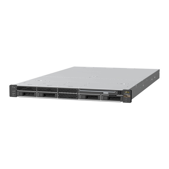
Preparing for Installation This chapter provides background information about the installation procedures for the Sun SPARC Enterprise T5120 and T5220 servers srom Oracle. This chapter contains these topics: “Server Overview” on page 1 ■ “Server Handling Precautions” on page 3 ■... - Page 14 SPARC Enterprise T5120 Server FIGURE: SPARC Enterprise T5220 Server FIGURE: Related Information Sun SPARC Enterprise T5120 and T5220 Servers Documentation ■ SPARC Enterprise T5120 Server Getting Started Guide ■ SPARC Enterprise T5220 Server Getting Started Guide ■ SPARC Enterprise T5120 Server Getting Started Guide (DC) ■...
-
Page 15: Server Handling Precautions
Sun SPARC Enterprise T5120 and T5220 Servers Service Manual ■ Server Handling Precautions Caution – Deploy the antitilt bar on the equipment rack before beginning an installation. Caution – The SPARC Enterprise T5220 server weighs approximately 55 lb (25. kg). Two people are required to lift and mount this 2U server into a rack enclosure when using the procedures in this document. -
Page 16: Input Power Information And Precautions
Input Power Information and Precautions The Sun SPARC Enterprise T5120 and T5220 servers are available in the following input power configurations: Two redundant, hot-swappable AC power supplies ■ Two redundant, DC power supplies ■ Note – Safety agency requirements prohibit manufacturers from changing a product from AC input to DC input or from DC input to AC input after the product has been removed from the agency approved manufacturing site. -
Page 17: Tools And Equipment Needed
Tools and Equipment Needed To install the system, you must have the following tools: No. 2 Phillips screwdriver ■ ESD mat and grounding strap ■ In addition, you must provide a system console device, such as one of the following: ASCII terminal ■... -
Page 18: Esd Precautions
SPARC Enterprise T5220 Server Getting Started Guide (DC) ■ Sun SPARC Enterprise T5120 and T5220 Servers Service Manual ■ ESD Precautions Electronic equipment is susceptible to damage by static electricity. Use a grounded antistatic wriststrap, footstrap, or equivalent safety equipment to prevent electrostatic damage (ESD) when you install or service the servers. - Page 19 Installation Overview FIGURE: Figure Legend Preparing for installation Installing the hardware Configuring the service processor Configuring the host software Preparing for Installation...
-
Page 20: Preparing For Installation
Preparing for Installation 1. Verify that you have received all of the components that ship with your server. 2. Gather configuration information for your system. See your system administrator for specific details, including these parameters: Netmask ■ IP address for the service processor ■... -
Page 21: Configuring The Service Processor
Tip – The serial terminal or a terminal emulator should be connected before you connect the power cables. As soon as AC power is connected to the system, the service processor immediately powers on and runs diagnostics. Diagnostic test failures will be printed on the serial terminal. For more information, refer to the Oracle Integrated Lights Out Manager 3.x Supplement for SPARC Enterprise T5120 and T5220 Servers. -
Page 22: Configuring The Host Software
3. Commit the changes to the service processor network parameters. See Step 3 “Power On the System for the First Time” on page 4. Power on the server from a keyboard using the ILOM software. Related Information “Power On the System” on page 59 ■... - Page 23 The service processor network management port (NET MGT port) ■ Power cables for the two system power supplies ■ Service processor management ports: There are two service processor ■ management ports for use with the ILOM service processor. The service processor serial management port (labeled SER MGT) uses an ■...
-
Page 24: Port, Connector, And Led Locations For Both Servers
Related Information Sun SPARC Enterprise T5120 and T5220 Servers Documentation ■ SPARC Enterprise T5120 Server Getting Started Guide ■ SPARC Enterprise T5220 Server Getting Started Guide ■ SPARC Enterprise T5120 Server Getting Started Guide (DC) ■ SPARC Enterprise T5220 Server Getting Started Guide (DC) ■... - Page 25 Front Panel USB Ports on the SPARC Enterprise T5120 Server FIGURE: Figure Legend System status indicators: Top to bottom: Hard drive HDD3 Locator LED button, Service Required LED, Power OK LED, Power button Hard drive HDD0 USB port 2 Hard drive HDD1 USB port 3 Hard drive HDD2 Rear Panel Cable Connectors and LEDs on the SPARC Enterprise T5220 Server...
-
Page 26: Related Information
(Continued) Figure Legend Gbit Enet port NET0 18 PCIe or XAUI slot 1 Gbit Enet port NET1 19 PCIe slot 5 10 Gbit Enet port NET2 20 PCIe slot 2 USB ports 2 and 3 are located on the front panel. Front Panel USB Ports on the SPARC Enterprise T5220 Server FIGURE: Figure Legend... -
Page 27: Slide Rail Assembly Notes For Both Servers
Slide Rail Assembly Notes for Both Servers The rackmounting kit has two slide rail assemblies. A slide rail assembly can be installed on either the right or left side of the rack. Note – The slide rail assemblies are different for the T5120 and T5220 servers. The removable mounting bracket of the SPARC Enterprise T5120 rails slides 13 in. - Page 28 The front, middle, and rear sections form the slide rail. The middle and rear sections ■ have holes for mounting screws, and adjust to fit rack depths from 24 in. (61 cm) to 36.5 in. (93 cm). The front section can be extended to allow movement of the server out of the rack.
- Page 29 Locating the Locks on the Slide Rail Assembly for the SPARC Enterprise T5220 FIGURE: Server Preparing for Installation...
-
Page 30: Cable Management Notes For Both Servers
Related Information “Cable Management Notes for Both Servers” on page 18 ■ “Installing the Servers in a Rack” on page 21 ■ Cable Management Notes for Both Servers The same cable management arm (CMA) is included with the rackmounting kit for each server. - Page 31 Installing the SPARC Enterprise T5120 and T5220 Servers This chapter provides instructions for installing the servers into an equipment rack. Note – If your rackmounting kit came with its own instructions, use the instructions in your rackmounting kit instead of the instructions in this chapter. After performing the server installation, proceed to “Powering On the System”...
-
Page 32: Install The Slide Rail Assemblies
Note – The procedures in this chapter are the same for both the 1U and 2U servers. The illustrations show a 2U server only as an example. The rackmounting kit (same for both 1U and 2U servers) contains two slide rail assemblies, which can be installed on either the right or left side of the rack. - Page 33 Unlocking the Slide Rail Assembly (Either Server) FIGURE: b. Pull the mounting bracket out until it locks in the extended position. c. Slide the mounting bracket release button out in the direction shown, then slide the mounting bracket out of the slide rail. Installing the SPARC Enterprise T5120 and T5220 Servers...
- Page 34 Location of the Mounting Bracket Release Button (Either Server) FIGURE: d. Press the metal lever (labeled Push) on the middle section of the sliding rail, then push the middle section back into the rack. SPARC Enterprise T5120 and T5220 Servers Installation Guide • October 2010...
- Page 35 Unlocking the Slide Rail Middle Section (Either Server) FIGURE: 2. Attach a mounting bracket to the right side of the chassis. a. Position the mounting bracket against the chassis. Ensure that the slide rail lock is at the front and the three keyed openings on the mounting bracket are aligned with the three locating pins on the side of the chassis.
- Page 36 Attaching a Mounting Bracket to the Chassis (Either Server) FIGURE: b. Ensure that the heads of the locating pins protrude though the keyed openings in the mounting bracket. Pull the mounting bracket toward the front of the chassis until the bracket locks into place with an audible click. c.
- Page 37 6. Attach a slide rail to the right front rack post. a. Loosely attach the front of a slide rail to the right front rack post using two screws. Note – Do not tighten the screws yet. Mounting a Slide Rail (Either Server) FIGURE: b.
- Page 38 Using the Slide Rail Spacing Tool to Adjust the Distance Between the Slide Rails FIGURE: (Either Server) b. Insert the right side of the tool into the front end of the right rail. c. Slide the end of the rail to the right or left as needed to allow the ends of the tool to enter the ends of both rails.
-
Page 39: Insert And Lock The Server In The Rack
▼ Insert and Lock the Server in the Rack 1. Insert the ends of the mounting brackets into the sliding rails. Caution – The weight of the servers on extended slide rails can be enough to overturn an equipment rack. Caution –... -
Page 40: Installing The Cable Management Arm For Both Servers
Mounting the Chassis on the Slide Rails (Either Server) FIGURE: Related Information “Installing the Cable Management Arm for Both Servers” on page 30 ■ Installing the Cable Management Arm for Both Servers The rackmounting kit for each server comes with the same cable management arm (CMA) assembly. -
Page 41: Install The Cable Management Arm
Note – The CMA includes velcro straps to secure the cables inside the CMA. Do not install the velcro straps until you install the CMA, connect the cables, and place the cabling inside the CMA as described in the following procedures. “Install the Cable Management Arm”... - Page 42 Inserting the CMA Rail Extension Into the Rear of the Left Slide Rail (Either Server) FIGURE: The right sides of the two CMA arms have hinged extensions. On the manufacturer’s instruction sheet, the smaller extension is called the CMA Connector for Inner Member. This extension attaches to the right mounting bracket.
- Page 43 Mounting the Inner CMA Connector (Either Server) FIGURE: 4. Insert the larger extension into the end of the right sliding rail. Installing the SPARC Enterprise T5120 and T5220 Servers...
- Page 44 Attaching the Outer CMA Connector (Either Server) FIGURE: 5. Insert the hinged plastic connector at the left side of the CMA fully into the CMA rail extension. The plastic tab on the CMA rail extension locks the hinged plastic connector in place.
-
Page 45: Verify The Operation Of The Slide Rails And The Cma
Mounting the Left Side of the Slide Rail (Either Server) FIGURE: Related Information “Verify the Operation of the Slide Rails and the CMA” on page 35 ■ “Cable Management Notes for Both Servers” on page 18 ■ ▼ Verify the Operation of the Slide Rails and the Tip –... - Page 46 2. Unlock the slide lock buttons at the right and left sides of the chassis. 3. Slowly pull the server out of the rack until the slide rails reach their stops. Unlocking the Slide Rail Assembly (Either Server) FIGURE: 4. Inspect any attached cables for binding or kinks. 5.
-
Page 47: Connecting The Server Cables For Both Servers
Rail Mounting Bracket Release Button (Either Server) FIGURE: 8. Verify that the CMA retracted without binding. 9. Adjust the cable straps and CMA as required to secure the cables. “Managing Cables With the CMA” on page Connecting the Server Cables for Both Servers To boot the server, you must connect and configure the network and serial ports. -
Page 48: Connect The Service Processor Serial Management Port
Note – When you are finished connecting the cables to the server, ensure that the server can slide smoothly in and out of the rack without binding or damaging the cables. See the section, “Verify the Operation of the Slide Rails and the CMA” on page This topic contains the following tasks: “Connect the Service Processor Serial Management Port”... - Page 49 Service Processor Serial Management Port – Rear Panel FIGURE: Use this port for server management. This port is needed to set up the service processor network management port, as detailed in “Enabling the Service Processor Network Management Port” on page Note –...
-
Page 50: Connect The Service Processor Network Management Port
▼ Connect the Service Processor Network Management Port The service processor network management port is labeled NET MGT. This port is located just to the right of the serial management (SER MGT) port on the rear panel. ● Connect a Category 5 cable from the NET MGT network management port to your network switch or hub. -
Page 51: Connect The Ethernet Network Cables
▼ Connect the Ethernet Network Cables The server has four network connectors, marked NET0, NET1, NET2, and NET3. These connectors are RJ-45 Gigabit Ethernet. ● Connect a Category 5 cable from your network switch or hub to Ethernet Port 0 (NET0) on the rear of the chassis. -
Page 52: Managing Cables With The Cma
Caution – The server goes into Standby mode and the service processor initializes as soon as the AC power cable is connected to the power source. ● Go to “Powering On the System for the First Time” on page 45 for instructions on connecting the server to AC power. -
Page 53: Dismounting The Servers
Securing the Server Cables With the CMA and Velcro Straps (Either Server) FIGURE: Caution – Verify the operation of the slide rails and CMA, and cable service loops. Perform the steps in the following procedure again before continuing: “Verify the Operation of the Slide Rails and the CMA”... - Page 54 Related Information Sun SPARC Enterprise T5120 and T5220 Servers Documentation ■ SPARC Enterprise T5120 and T5220 Servers Service Manual ■ SPARC Enterprise T5120 and T5220 Servers Installation Guide • October 2010...
-
Page 55: Powering On The System
Powering On the System This chapter includes instructions for booting the servers and for enabling the service processor network management port. This chapter contains the following topics: “Powering On the System for the First Time” on page 45 ■ “Enabling the Service Processor Network Management Port” on page 51 ■... -
Page 56: Ilom System Console
Related Information “ILOM System Console” on page 46 ■ “Enabling the Service Processor Network Management Port” on page 51 ■ “Verifying System Functionality” on page 67 ■ ILOM System Console When you power on the system, the boot process begins under the control of the Integrated Lights Out Manager (ILOM) system console. -
Page 57: Power On The System For The First Time
Related Information “Power On the System for the First Time” on page 47 ■ “Configure the Service Processor Network Management Port” on page 55 ■ ▼ Power On the System for the First Time 1. Confirm that you have completed all of the preparations for installation. See the instructions in “Preparing for Installation”... -
Page 58: Server Connections
Server Connections FIGURE: Figure Legend Power Cables RJ-45 to DB-25 crossover adapter Ethernet cables RJ-45 to DB-9 crossover adapter Service processor to ethernet Terminal device NET MGT to network (optional) SPARC Enterprise T5120 and T5220 Servers Installation Guide • October 2010... - Page 59 5. Plug the power cords into the power supplies and into separate power sources. To provide redundancy, plug both power supplies into separate power sources. The system can operate with only one power connection, but there is no redundancy in this case. The service processor runs on the 3.3V standby voltage.
- Page 60 8. When prompted, follow the onscreen instructions for configuring the Solaris Operating System on your host and enter the following configuration information. You will be prompted to confirm the configuration several times, enabling confirmation and changes. If you are not sure how to respond to a particular value, you can accept the default, and make future changes when the Solaris OS is running.
-
Page 61: Enabling The Service Processor Network Management Port
Time Zone Select the time zone. Date and Time Accept the default date and time or change the values. root Password Enter the root password twice. This password is for the superuser account for the Solaris OS on this server. This password is not the SP password. 9. - Page 62 Properties: commitpending = (Cannot show property) dhcp_server_ip = 10.8.31.5 ipaddress = 10.8.31.188 ipdiscovery = dhcp ipgateway = 10.8.31.248 ipnetmask = 255.255.252.0 macaddress = 00:14:4F:7E:83:4F pendingipaddress = 10.8.31.188 pendingipdiscovery = dhcp pendingipgateway = 10.8.31.248 pendingipnetmask = 255.255.252.0 state = enabled Commands: show If your network does not use DHCP, the network management port is not operational until you configure network settings for the service processor.
-
Page 63: Logging Into The Service Processor
Logging Into the Service Processor If you are powering on the system for the first time after installation, use the service processor serial port to power on the system and run POST. See “Log Into the Service Processor Using the Serial Management Port” on page If the network management port has already been configured, you can use it instead of the serial management port. - Page 64 Federal Acquisitions: Commercial Software -- Government Users Subject to Standard License Terms and Conditions. Warning: password is set to factory default. -> set /SP/users/root password Enter new password: ******** Enter new password again: ******** -> Note – After the root password has been set, on subsequent reboots, the ILOM CLI login prompt is displayed.
-
Page 65: Configure The Service Processor Network Management Port
▼ Configure the Service Processor Network Management Port Note – If your network allows the use of DHCP, this configuration is performed automatically the first time you boot the system. Use this procedure only when: You are unable to use DHCP on your network. ■... - Page 66 dhcp - Set up the network connection with a dynamically created IP ■ configuration. If you choose to use a dynamically created IP address (use DHCP to retrieve the network setting), set pendingipdiscovery to dhcp. -> set /SP/network pendingipdiscovery=dhcp Set 'pendingipdiscovery' to 'dhcp' static - Set up the network connection with a static IP configuration.
- Page 67 dhcp_server_ip = xxx.xxx.xxx.xxx ipaddress = xxx.xxx.xxx.xxx ipdiscovery = dhcp ipgateway = xxx.xxx.xxx.xxx ipnetmask = 255.255.252.0 macaddress = 00:14:4F:3F:8C:AF pendingipaddress = xxx.xxx.xxx.xxx pendingipdiscovery = static pendingipgateway = xxx.xxx.xxx.xxx pendingipnetmask = 255.255.255.0 state = enabled Commands: show -> Note – After setting the configuration parameters, you must enter the set /SP/network commitpending=true command for the new values to take affect.
-
Page 68: Log Into The Service Processor Using The Network Management Port
▼ Log Into the Service Processor Using the Network Management Port Note – You must configure the service processor parameters shown in “Configure the Service Processor Network Management Port” on page 55 before you can use the network management port. ●... -
Page 69: Power On The System
▼ Power On the System 1. Perform the following steps to verify that there are no faults: a. Set the virtual keyswitch to diag mode so that POST will run in Service mode. -> set /SYS keyswitch_state=diag b. To initiate the power-on sequence, type the start /SYS command. An ILOM CLI alert message appears on the system console. -
Page 70: Connect To The System Console
{8} ok 2. Type the console escape sequence (by default #. (Hash-Period)) to return to the ILOM prompt. 3. Check the POST execution result with the following command: -> show /SP/faultmgmt -level all Note – Depending on the configuration of ILOM, POST variables, and whether POST detected faults or not, the server might boot, or the system might remain at the ok prompt. -
Page 71: Perform A Normal System Initialization
Related Information “Perform a Normal System Initialization” on page 61 ■ Sun SPARC Enterprise T5120 and T5220 Servers Documentation ■ Sun SPARC Enterprise T5120 and T5220 Servers Service Manual ■ ▼ Perform a Normal System Initialization 1. Type the start /SYS command. ->... -
Page 72: Devices In The Openboot Device Tree
0:1:0>Extended Memory Tests..Done 2007-12-14 16:45:28.800 0:1:0>INFO: 2007-12-14 16:45:28.806 0:1:0> POST Passed all devices. 2007-12-14 16:45:28.816 0:1:0>POST: Return to VBSC. 2007-12-14 16:45:28.824 0:1:0>Master set ACK for vbsc runpost command and spin... SPARC Enterprise T5220, No Keyboard Copyright 2007 Sun Microsystems, Inc. All rights reserved. - Page 73 * The logical device names might appear differently on your system, depending on the number and type of add-on disk controllers in- stalled. Device Identifiers and Devices TABLE: Device Identifiers Devices CPU strand (Number: 0-63) /SYS/MB/CMPcpu_number/Pstrand_number PCIe slot (Number: 0-5) /SYS/MB/RISERriser_number/PCIEslot_number XAUI card (Number: 0-1) /SYS/MB/RISERriser_number/XAUIcard_number...
-
Page 74: Boot The Solaris Operating System
▼ Boot the Solaris Operating System The Solaris OS is preinstalled on the servers on the disk in slot 0. The Solaris OS is not configured (that is, the sys-unconfig command was run in the factory). If you boot the system from this disk, you will be prompted to configure the Solaris OS for your environment. -
Page 75: Avoid Booting The Solaris Operating System At Startup
Setting default IPv4 interface for multicast: add net 224.0/4: gateway xxxx syslog service starting. volume management starting. Creating new rsa public/private host key pair Creating new dsa public/private host key pair The system is ready. hostname console login: Related Information “Avoid Booting the Solaris Operating System at Startup”... -
Page 76: Power Cycle The System
2. It is not necessary to power the system off and on to simply reset the system. Related Information “Power Cycle the System” on page 66 ■ Sun SPARC Enterprise T5120 and T5220 Servers Documentation ■ Sun SPARC Enterprise T5120 and T5220 Servers Administration Guide ■... -
Page 77: Verifying System Functionality
Note – To perform an immediate and ungraceful shutdown, use the stop -force -script /SYS or stop -script /SYS commands. These commands stop everything immediately, so ensure that all data is saved before entering these commands. 4. Type the start /SYS command. ->... - Page 78 SPARC Enterprise T5120 and T5220 Servers Installation Guide • October 2010...
-
Page 79: Updating The Firmware
Updating the Firmware This topic provides instructions for updating SP firmware. It contains the following sections: “flashupdate command” on page 69 ■ “Update the Firmware” on page 70 ■ flashupdate command The flashupdate command updates both the service processor firmware and the server firmware. -
Page 80: Update The Firmware
▼ Update the Firmware 1. Ensure that the ILOM service processor network management port is configured. This configuration is required to access the new flash image over the network. See “Configure the Service Processor Network Management Port” on page 2. Open an SSH session to connect to the service processor. % ssh root@xx.xxx.xx.x Are you sure you want to continue connecting (yes/no)? yes Password: password (nothing displayed) - Page 81 Full path name to the flash image that the IP address can access ■ The command usage is as follows: load [-script] -source tftp://xxx.xxx.xx.xx/pathname where: -script – Does not prompt for confirmation and acts as if yes was specified ■ -source –...
- Page 82 Identifying DOC Device Type(G3/G4/H3) ... Configuring network interfaces...Internet Systems Consortium DHCP Client V3.0.1 Copyright 2007 Internet Systems Consortium. All rights reserved. For info, please visit http://www.isc.org/products/DHCP eth0: config: auto-negotiation on, 100FDX, 100HDX, 10FDX, 10HDX. Listening on LPF/eth0/00:14:4f:3f:8c:af Sending on LPF/eth0/00:14:4f:3f:8c:af Sending on Socket/fallback DHCPDISCOVER on eth0 to 255.255.255.255 port 67 interval 6...
-
Page 83: Selecting A Boot Device
Selecting a Boot Device This section provides instructions on selecting a boot device: “Selecting a Boot Device” on page 73 ■ Related Information “Selecting a Boot Device” on page 73 ■ “To Select a Boot Device” on page 74 ■ Selecting a Boot Device You specify the boot device by setting an OpenBoot configuration variable called boot-device. -
Page 84: To Select A Boot Device
▼ To Select a Boot Device ● At the ok prompt, type: ok setenv boot-device device-specifier where the device-specifier is one of the following: cdrom – Specifies the DVD drive ■ disk – Specifies the system boot disk (internal disk 0 by default) ■... -
Page 85: Installing The Servers With The Express Rail Rackmounting Kit
Installing the Servers With the Express Rail Rackmounting Kit This section provides instructions for installing the servers in an equipment rack with express (snap-in) rails. The express rail rackmounting kit installs quickly, and does not require mounting screws or nuts. The kit and the installation procedures are the same for both the SPARC Enterprise T5120 and T5220 servers. -
Page 86: Slide Rail Assembly Notes For The Express Rail Rackmounting Kit
Slide Rail Assembly Notes for the Express Rail Rackmounting Kit The express rail rackmounting kit has two slide rail assemblies. A slide rail assembly can be installed on either the right or left side of the rack. Each slide rail assembly consists of a three-section slide rail and a removable mounting bracket. - Page 87 The removable mounting bracket slides 14.5 in. (37 cm) out of the slide rail, then ■ locks in place. If you unlock the mounting bracket at this point, it slides an additional 14.5 in. (37 cm) before separating from the slide rail. You can then mount the mounting bracket to the right or left side of the server chassis.
-
Page 88: Installing The Servers In A Rack With Express Rails
Related Information “Installing the Servers in a Rack With Express Rails” on page 78 ■ Installing the Servers in a Rack With Express Rails Note – Ensure that you have all of the parts in the rackmounting kit before you begin installation. - Page 89 Unlocking the Express Rail Slide Rail Assembly FIGURE: b. Pull the mounting bracket out until it stops. c. Slide the mounting bracket release button to the left, then slide the mounting bracket completely out of the slide rail. Installing the Servers With the Express Rail Rackmounting Kit...
- Page 90 Express Rail Mounting Bracket Release Button FIGURE: 2. Attach a mounting bracket to the right side of the server chassis. a. Position the mounting bracket against the chassis. Ensure that the slide rail lock is at the front and the keyed openings on the mounting bracket are aligned with the locating pins on the side of the chassis.
- Page 91 Attaching an Express Rail Mounting Bracket to the Chassis FIGURE: b. Ensure that the heads of the four locating pins protrude through the keyed openings in the mounting bracket. Slide the mounting bracket toward the front of the chassis until the bracket locks into place with an audible click. c.
- Page 92 Express Rail Slide Rails Orientation for Installation FIGURE: 5. Extend the slide rails (outer section) to fit the rack and attach the slide rails to the rack. You hear an audible click when the rails securely attach to the rack. SPARC Enterprise T5120 and T5220 Servers Installation Guide •...
-
Page 93: Insert And Lock The Server In The Rack
Attaching Express Slide Rails to the Rack FIGURE: Caution – Deploy the antitilt feature on the rack before continuing the installation. Related Information “Insert and Lock the Server in the Rack” on page 83 ■ ▼ Insert and Lock the Server in the Rack 1. - Page 94 2. Insert the ends of the mounting brackets into the sliding rails. 3. Slide the server approximately halfway into the chassis. Inserting Express Rail Mounting Brackets Into the Slide Rails FIGURE: 4. Slide the green release tab. 5. Push the server all the way into the rack until it locks into place. SPARC Enterprise T5120 and T5220 Servers Installation Guide •...
- Page 95 Sliding the Express Rail Release Tab and Securing the Server in the Rack FIGURE: Caution – Before continuing, verify that the server is securely mounted in the rack and that the slide rails are locked in the mounting brackets. Related Information ■...
-
Page 96: Installing The Cable Management Arm
Installing the Cable Management Arm The rackmounting kit for each server comes with the same cable management arm (CMA) assembly. The CMA installation procedures are the same for both servers. “Installing the Cable Management Arm for Both Servers” on page Related Information “Installing the Cable Management Arm for Both Servers”... -
Page 97: Assembling And Installing Dc Power Cables For The Sun Sparc Enterprise T5120 Server
Assembling and Installing DC Power Cables for the Sun SPARC Enterprise T5120 Server This section provides the following DC input power information for the Sun SPARC Enterprise T5120 server. Note – The procedures in this section are only for the Sun SPARC Enterprise T5120 server. -
Page 98: Dc Supply And Ground Conductor Requirements
Related Information “DC Supply and Ground Conductor Requirements” on page 88 ■ DC Supply and Ground Conductor Requirements The server must meet the following: Suitable conductor material: use copper conductors only ■ Power supply connections through the input connector: 12 AWG (between the ■... -
Page 99: Overcurrent Protection Requirements
Related Information “Overcurrent Protection Requirements” on page 89 ■ Overcurrent Protection Requirements Overcurrent protection devices must be provided as part of each equipment rack. ■ Circuit breakers must be located between the DC power source and the server. Use ■ one 20 A fast-trip double-pole DC-rated circuit breaker for each power supply unit. -
Page 100: Assemble The Dc Input Power Cables
Before you begin the installation procedure, verify that the required conditions described in the following table have been satisfied. Prerequisites Not Covered by the DC Cable Installation Procedure TABLE: Prerequisite Condition Responsible Party Install a DC power source that meets the server’s input power Customer specifications. - Page 101 DC Connection Parts FIGURE: Figure Legend Strain relief housing DC input plug Cage clamp operating lever 3. Locate the three wires coming from the DC power source that will be used in the connection to your unit: -48V or -60V (negative terminal) ■...
- Page 102 4. Strip 5/16 inches (8 mm) of insulation from each of the wires coming from the DC power source. Do not strip more than 5/16 inches (8 mm) from each wire. Doing so leaves uninsulated wire exposed from the DC connector after the assembly is complete. Stripping the Insulation From the Wire FIGURE: Figure Legend...
- Page 103 Opening the DC Input Plug Cage Clamp Using the Cage Clamp Operating FIGURE: Lever Figure Legend Top of input plug Assembling and Installing DC Power Cables for the Sun SPARC Enterprise T5120 Server...
- Page 104 Opening the Cage Clamp Using a Screwdriver FIGURE: Figure Legend Top of input plug 6. Feed the exposed section of the appropriate wire into the round hole in the DC input plug. Connector Wiring Assignments FIGURE: Figure Legend Top of connector From chassis ground (green/yellow) From -48V or -60V return From -48V or -60V...
-
Page 105: Install The Strain Relief Housings
Note – If you need to remove a wire from the DC input plug, insert the cage clamp operating lever or a small screwdriver as described in Step 5, and pull the wire from the DC input plug. 7. Release the lever or remove the tool to secure the wire into the connector. 8. - Page 106 Inserting the Bottom Portion of the Strain Relief Housing FIGURE: 2. Route the three wires coming from the DC power source through the opening at the end of the bottom portion of the strain relief housing. Routing the Wires out of the Bottom Portion of the Strain Relief Housing FIGURE: 3.
- Page 107 Securing the Wires to the Strain Relief Housing FIGURE: 4. Loop the tie wrap over the wires and back out of the strain relief housing, and tightening the tie wrap to secure the wires to the strain relief housing. 5. Lower the top portion of the strain relief housing so that the three prongs on the top portion insert into the openings in the DC input plug.
-
Page 108: Connecting The Dc Input Power Cords To The Server
Assembling the Strain Relief Housing FIGURE: Related Information “Connecting the DC Input Power Cords to the Server” on page 98 ■ ▼ Connecting the DC Input Power Cords to the Server 1. Ensure that the circuit breaker to your power source is turned off. Caution –... - Page 109 4. Connect the -48v or -60V return to the -48 v or -60V wires to the circuit breaker. 5. Connect the power wiring to the server by plugging each power cable into the server power supply units. 6. When you are ready to power up the server, close the circuit breaker and following booting procedure described in, “Powering On the System for the First Time”...
- Page 110 SPARC Enterprise T5120 and T5220 Servers Installation Guide • October 2010...
-
Page 111: Input Power Restrictions
Assembling and Installing DC Power Cables for the Sun SPARC Enterprise T5220 Server This section provides the following DC input power information for the Sun SPARC Enterprise T5220 server: The procedures in this section are only for the Sun SPARC Enterprise T5220 server. Note –... -
Page 112: Input Power Restrictions
Input Power Restrictions The following restrictions apply to the Sun SPARC Enterprise T5220 server with DC input power: The DC version of the server must be installed in a restricted-access location. ■ According to the intent of the National Electrical Code, a restricted-access location is an area intended for qualified or trained personnel only and has access controlled by a locking mechanism, such as a key lock or an access card system. - Page 113 Caution – You must restrict the connection of the server to the DC power source to minimize the possibility that transient energy will appear on the main input to the equipment. The DC battery power source must be in the same premises as the server. The server cannot be in one building with the power source in another building.
- Page 114 This section contains the following tasks: “Assemble the DC Input Power Cables” on page 104 ■ “Connect the DC Input Power Cords” on page 107 ■ ▼ Assemble the DC Input Power Cables 1. Turn off power from the DC power source using the circuit breakers. Caution –...
- Page 115 3. Locate the three wires coming from your DC power source that will be used in the connection to your unit: -48V or -60V (negative terminal) ■ Chassis ground ■ -48V or -60V Return (positive terminal) ■ Note – Depending on the DC power source, the -48V or -60V (negative terminal) might be marked with a minus (-) symbol, and the -48V or -60V Return (positive terminal) might be marked with a positive (+) symbol.
- Page 116 Opening the Cage Clamp Using the Cage Clamp Tool FIGURE: 6. Feed the exposed section of the appropriate wire into the round plug hole in the DC input plug. SPARC Enterprise T5120 and T5220 Servers Installation Guide • October 2010...
-
Page 117: Connect The Dc Input Power Cords
Connector Wiring Assignments FIGURE: Figure Legend From -48V or -60V From Chassis ground (green/yellow) From -48V or -60V Return Note – If you need to remove a wire from the DC input plug, insert the cage clamp operating tool or a small screwdriver into the slot directly above the wire and push in. - Page 118 Caution – Do not proceed with these instructions until you have turned off the power from the DC power source through the circuit breakers. 2. Route the power cables in the rack and secure the cables with nylon tie wraps. 3.
-
Page 119: Index
Index Symbols #. escape sequence for system console, 66 DB-9 TTY connector, 11 DC input plug, 91, 104 DC input power, 87, 101 accessing ILOM command line, 53 DC input power cable, assembling, 89, 103 adapters for serial cables, 39 DC input power, connecting, 98, 107 address, IP, 8 definitions, See terms, 21... - Page 120 mounting brackets, 78 ports, slots, and LEDs illustrated, 12, 13 installing optional components, 5 power cycling the system, 66 IP address, 8 powering on the system for the first time, 45 poweroff command, 66 poweron command, 59, 61 LEDs, ports, and slots illustrated, 12, 13 left and right sides defined, 21 levers, locking, See "slide rail assembly locks"...
- Page 121 stop bit, 47 strain relief housing, 91, 95 system console escape sequence #., 66 terms left and right sides, 21 slide rail assembly, 15, 76 topic guidelines, 1, 21, 45, 73, 75, 87, 101 TTYA serial port, 11 uadmin command, 65, 66 unlocking mounting bracket, 78 Index...
- Page 122 SPARC Enterprise T5120 and T5220 Servers Installation Guide • October 2010...
Need help?
Do you have a question about the SPARC T5120 and is the answer not in the manual?
Questions and answers