Sun Oracle SPARC T3-1 Installation Manual
Hide thumbs
Also See for SPARC T3-1:
- Installation manual (112 pages) ,
- Getting started manual (7 pages)

Related Manuals for Sun Oracle SPARC T3-1


Summary of Contents for Sun Oracle SPARC T3-1
-
Page 1: Installation Guide
SPARC T3-1 Server Installation Guide Part No.: E21414-04 March 2012... - Page 2 Copyright © 2010, 2012, Oracle and/or its affiliates. All rights reserved. This software and related documentation are provided under a license agreement containing restrictions on use and disclosure and are protected by intellectual property laws. Except as expressly permitted in your license agreement or allowed by law, you may not use, copy, reproduce, translate, broadcast, modify, license, transmit, distribute, exhibit, perform, publish, or display any part, in any form, or by any means.
-
Page 3: Table Of Contents
Contents Using This Documentation vii Preparing for the Installation 1 Installation Task Overview 1 Server Overview 2 Server Specifications 4 Physical Specifications 4 Minimum Clearance for Service Access 5 Environmental Specifications 6 Input Power Overview 7 Guidelines for Planning Power Requirements Acoustic Noise Emissions 10 Agency Compliance Specifications 10 Operating Environment Requirements 11... - Page 4 Connect a Terminal or Emulator to the SER MGT Port 57 ▼ Power On the Server for the First Time 57 ▼ Verify System Functionality 59 ▼ Assign a Static IP Address to the Service Processor 60 SPARC T3-1 Server Installation Guide • March 2012...
- Page 5 Glossary 63 Index 67 Contents...
- Page 6 SPARC T3-1 Server Installation Guide • March 2012...
-
Page 7: Using This Documentation
Using This Documentation This installation guide provides instructions, background information, and reference material to help you install Oracle’s SPARC T3-1 Server. “Related Documentation” on page vii ■ “Feedback” on page viii ■ “Support and Accessibility” on page viii ■ Related Documentation... - Page 8 Provide feedback on this documentation at: http://www.oracle.com/goto/docfeedback Support and Accessibility Description Links Access electronic support http://support.oracle.com through My Oracle Support For hearing impaired: http://www.oracle.com/accessibility/support.html Learn about Oracle’s http://www.oracle.com/us/corporate/accessibility/index.html commitment to accessibility viii SPARC T3-1 Server Installation Guide • March 2012...
-
Page 9: Preparing For The Installation
Preparing for the Installation This chapter provides background information about the installation procedures for the server. This chapter contains these topics: “Installation Task Overview” on page 1 ■ “Server Overview” on page 2 ■ “Server Specifications” on page 4 ■ “Front Panel Components”... -
Page 10: Server Overview
Server Installation Task Flowchart FIGURE: Server Overview The server is a rack-mountable system with a 2RU form-factor. SPARC T3-1 Server Installation Guide • March 2012... - Page 11 SPARC T3-1 Server FIGURE: The following list identifies the items that comprise the server’s base configuration: 2 RU system enclosure with rack-mount slide hardware. ■ Motherboard with a service processor, two embedded RAID 0, 1, and 1E hard ■ drive controllers, system configuration PROM, and other system infrastructure components.
-
Page 12: Server Specifications
88.6 mm Weight, approximate (with 2 power supplies and 16 HDDs, but 60 lb 27.2 kg without PCI cards and rackmount hardware) Related Information “Minimum Clearance for Service Access” on page 5 ■ SPARC T3-1 Server Installation Guide • March 2012... -
Page 13: Minimum Clearance For Service Access
Minimum Clearance for Service Access Minimum Clearances Needed TABLE: Description Clearance Clearance, front of system 36 in. (91 cm) Clearance, rear of system 36 in. (91 cm) Related Information “Physical Specifications” on page 4 ■ Preparing for the Installation... -
Page 14: Environmental Specifications
Electrostatic discharge (ESD) is easily generated and less easily dissipated in areas where the relative humidity is below 35%, and becomes critical when levels drop below 30%. SPARC T3-1 Server Installation Guide • March 2012... -
Page 15: Input Power Overview
ETE-1010-02 Rev A Related Information “Server Specifications” on page 4 ■ Input Power Overview The SPARC T3-1 server can be equipped with one or two autoranging power supplies. They have the following input power requirements: Specification Values System rating 100Vac, 13A max, 50/60 Hz... -
Page 16: Guidelines For Planning Power Requirements
1.6 mA Maximum Server Configuration Specifications Under Nominal Temperature and Voltage Conditions (16 core, 1.6 GHz processor, with sixteen 8 GB DIMMs, 8 HDDs, 6 PCIe I/O cards) Idle input power 416 W SPARC T3-1 Server Installation Guide • March 2012... - Page 17 SPARC T3-1 Server (8-Disk Capacity) Power Specifications (Continued) TABLE: Peak input power running SpecJBB 582 W Minimum Server Configuration Specifications Under Nominal Temperature and Voltage Conditions (16 core, 1.6 GHz processor, with four 2 GB DIMMs, 1 HDD, no PCIe I/O cards)
-
Page 18: Acoustic Noise Emissions
* 1 B = 10 dB Related Information “Server Specifications” on page 4 ■ Agency Compliance Specifications Refer to the SPARC T3-1 Server Safety and Compliance Guide for a full list of agency compliance specifications. Related Information “Server Specifications” on page 4 ■... -
Page 19: Operating Environment Requirements
Operating Environment Requirements Your environmental control system must provide intake air for the servers that complies with the limits specified in“Environmental Specifications” on page To avoid overheating, do not direct warmed air: Toward the front air intake of the server ■... -
Page 20: Front Panel Components
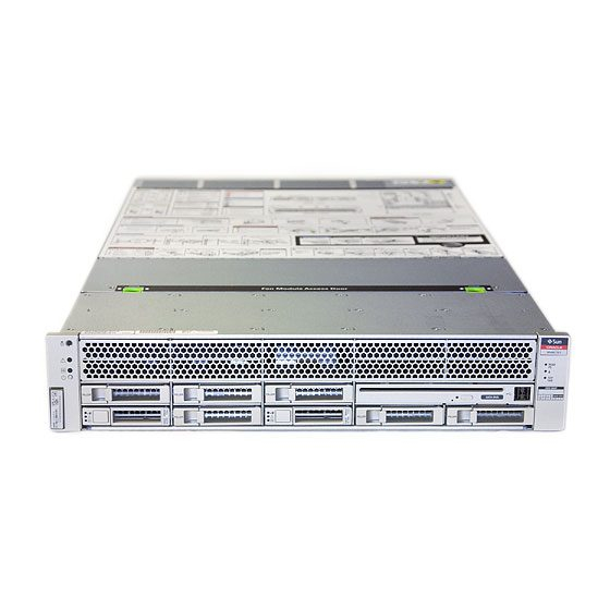
“Operating Environment Requirements” on page 11 ■ “Minimum Clearance for Service Access” on page 5 ■ Front Panel Components The following figure shows the components that are accessible on the server front panel. SPARC T3-1 Server Installation Guide • March 2012... - Page 21 Components on the Server Front Panel (Eight-Disk Backplane Configuration) FIGURE: Figure Legend System controls and indicators Hard drive HDD5 RFID tag Hard drive HDD6 Hard drive HDD0 Hard drive HDD7 Hard drive HDD1 SATA DVD module Hard drive HDD2 USB port 2 Hard drive HDD3 USB port 3 Hard drive HDD4...
-
Page 22: Front Panel System Leds And Buttons
“Rear Panel System LEDs and Button” on page 18 ■ Front Panel System LEDs and Buttons The following figure shows the layout of the system LEDs and the power control button on the front panel. SPARC T3-1 Server Installation Guide • March 2012... - Page 23 Front Panel System LEDs and Power Buttons FIGURE: Figure Legend Locator LED and button Power Supply Service Required LED Fault - Service Required LED System Overterperature Fault - Service Required LED Power OK LED Top Fan Fault - Service Required LED Power ON/Standby button Preparing for the Installation...
- Page 24 Related Information “Server Overview” on page 2 ■ “Front Panel Components” on page 12 ■ “Rear Panel Components” on page 17 ■ “Rear Panel System LEDs and Button” on page 18 ■ SPARC T3-1 Server Installation Guide • March 2012...
-
Page 25: Rear Panel Components
Rear Panel Components The following figure shows the components that are accessible on the server rear panel. Components on the Server Rear Panel FIGURE: Figure Legend Power supply 0 12 Hole for pressing the physical presence button Power supply 1 13 USB port 0 Locator LED button 14 USB port 1... -
Page 26: Rear Panel System Leds And Button
The following figure shows location of the system LEDs and the locator button on the rear panel. Rear Panel System LEDs FIGURE: Figure Legend Locator LED and button Power OK LED Fault - Service Required LED SPARC T3-1 Server Installation Guide • March 2012... -
Page 27: Server Handling Precautions
Rear Panel System LED Descriptions TABLE: LED or Button Icon or Label Description Locator LED The Locator LED can be turned on to identify a particular system. When on, it and button blinks rabidly. There are two methods for turning a Locator LED on: (white) •... -
Page 28: Esd Precautions
Wear an antistatic grounding strap connected to a metal surface on the chassis when you work on system components. Related Information “Server Handling Precautions” on page 19 ■ SPARC T3-1 Server Installation Guide • March 2012... -
Page 29: Tools Needed For Installation
Tools Needed for Installation To install the system, you must have the following tools: No. 2 Phillips screwdriver ■ ESD mat and grounding strap ■ You must also provide a system console device, such as one of the following: ASCII terminal ■... - Page 30 SPARC T3-1 Server Installation Guide • March 2012...
-
Page 31: Installing The Server
Installing the Server These topics explain how to install the server in an equipment rack: “Stabilize the Rack” on page 23 ■ “Slide Rail Assembly Overview” on page 23 ■ “Install the Screw-Mount Slide Rail Assemblies” on page 27 ■ “Install the Snap-In Slide Rail Assemblies”... -
Page 32: Slide-Rail Assembly Details For The Screw-Mount Rack Mount Kit
24 in. (61 cm) to 36.5 in. (93 cm). The front section extends out of the middle section, which allows the server to be ■ postioned far enough out of the rack for many service operationsto be performed. SPARC T3-1 Server Installation Guide • March 2012... - Page 33 The removable mounting bracket slides 14 in. (35.5 cm) out of the slide rail, then ■ locks in place. If you unlock the mounting bracket at this point, it slides an additional 12 in. (30 cm) before separating from the slide rail. That there are five locks in a slide rail assembly.
-
Page 34: Slide Rail Assembly Details For The Snap-In Rack Mount Kit
14.5 in. (37 cm) before separating from the slide rail. There are six locks in a slide rail assembly. Four are on the mounting bracket. Two locks are on the slide rail. SPARC T3-1 Server Installation Guide • March 2012... -
Page 35: Install The Screw-Mount Slide Rail Assemblies
Locating the Locks on the Slide Rail Assembly FIGURE: Related Information “Install the Screw-Mount Slide Rail Assemblies” on page 27 ■ “Install the Snap-In Slide Rail Assemblies” on page 34 ■ ▼ Install the Screw-Mount Slide Rail Assemblies 1. Stabilize the rack by extending its anti-tilt legs. See your rack documentation for instructions. - Page 36 Pull the mounting bracket out until it locks in the extended position. c. Slide the mounting bracket release button out in the direction shown, then slide the mounting bracket out of the slide rail. SPARC T3-1 Server Installation Guide • March 2012...
- Page 37 Location of the Mounting Bracket Release Button FIGURE: d. Press the metal lever (labeled Push) on the middle section of the sliding rail, then push the middle section back into the rack. Installing the Server...
- Page 38 Position the mounting bracket against the chassis. Ensure that the slide rail lock is at the front and the three keyed openings on the mounting bracket are aligned with the three locating pins on the side of the chassis. SPARC T3-1 Server Installation Guide • March 2012...
- Page 39 Attaching a Mounting Bracket to the Chassis FIGURE: b. Ensure that the heads of the locating pins protrude though the keyed openings in the mounting bracket. Pull the mounting bracket toward the front of the chassis until the bracket locks into place with an audible click. c.
- Page 40 9. Use the slide rail spacing tool to adjust the distance between the slide rails. a. At the front of the rack, plug the left side of the tool into slots at the end of the left rail. SPARC T3-1 Server Installation Guide • March 2012...
- Page 41 Using the Slide Rail Spacing Tool to Adjust the Distance Between the Slide Rails FIGURE: b. Insert the right side of the tool into the front end of the right rail. c. Slide the end of the rail to the right or left as needed to allow the ends of the tool to enter the ends of both rails.
-
Page 42: Install The Snap-In Slide Rail Assemblies
Unlocking the Express Rail Slide Rail Assembly FIGURE: b. Pull the mounting bracket out until it stops. c. Slide the mounting bracket release button to the left, then slide the mounting bracket completely out of the slide rail. SPARC T3-1 Server Installation Guide • March 2012... - Page 43 Express Rail Mounting Bracket Release Button FIGURE: 2. Attach a mounting bracket to the right side of the server chassis. a. Position the mounting bracket against the chassis. Ensure that the slide rail lock is at the front and the keyed openings on the mounting bracket are aligned with the locating pins on the side of the chassis.
- Page 44 3. Attach the second mounting bracket to the left side of the server chassis. 4. Orient the slide rails, ensuring that the ball bearing tracks (labeled FRONT) are forward. SPARC T3-1 Server Installation Guide • March 2012...
- Page 45 Express Rail Slide Rails Orientation for Installation FIGURE: 5. Extend the slide rails (outer section) to fit the rack and attach the slide rails to the rack. You hear an audible click when the rails securely attach to the rack. Installing the Server...
-
Page 46: Insert And Lock The Server In The Rack
▼ Insert and Lock the Server in the Rack 1. Insert the ends of the mounting brackets into the sliding rails. Caution – The weight of the servers on extended slide rails can be enough to overturn an equipment rack. SPARC T3-1 Server Installation Guide • March 2012... - Page 47 Caution – The server weighs approximately 60 lb (25 kg). Two people are required to lift and mount the server into a rack enclosure when using the procedures in this chapter. Caution – Before continuing, verify that the server is securely mounted in the rack, and that the slide rails are locked to the mounting brackets.
-
Page 48: Install The Cable Management Arm
At the rear of the rack, plug the CMA rail extension into the end of the left sliding rail assembly. The tab at the front of the rail extension clicks into place. SPARC T3-1 Server Installation Guide • March 2012... - Page 49 Inserting the CMA Rail Extension Into the Rear of the Left Slide Rail FIGURE: The right sides of the two CMA arms have hinged extensions. On the manufacturer’s instruction sheet, the smaller extension is called the CMA Connector for Inner Member. This extension attaches to the right mounting bracket.
- Page 50 Mounting the Inner CMA Connector FIGURE: 4. Insert the larger extension into the end of the right sliding rail. SPARC T3-1 Server Installation Guide • March 2012...
- Page 51 Attaching the Outer CMA Connector FIGURE: 5. Insert the hinged plastic connector at the left side of the CMA fully into the CMA rail extension. The plastic tab on the CMA rail extension locks the hinged plastic connector in place. Installing the Server...
-
Page 52: Verify Correct Operation Of The Slide Rails And The Cma
Perform this procedure both before and after you install the server cables in the CMA. Perfoming the procedure before the CMA contains cables helps ensure that it extends and contracts smoothly before the cables are added. SPARC T3-1 Server Installation Guide • March 2012... - Page 53 Note – The CMA includes velcro straps to secure the cables inside the CMA. Do not install the velcro straps until you have installed the CMA, connected the cables, and placed the cabling inside the CMA. Tip – Two people are needed for this procedure, one to move the server in and out of the rack, and one to observe the cables and CMA.
- Page 54 The server should slide smoothly into the rack without binding. Rail Mounting Bracket Release Button FIGURE: 8. Verify that the CMA retracted without binding. 9. Adjust the cable straps and CMA as required to secure the cables. SPARC T3-1 Server Installation Guide • March 2012...
-
Page 55: Connecting The Server Cables
Connecting the Server Cables These topics explain how to connect the data and power cables to the server: “Cabling Requirements” on page 47 ■ “Connect the SER MGT Port Cable” on page 49 ■ “Connect the NET MGT Port Cable” on page 50 ■... - Page 56 System messages might be lost after 60 seconds if a terminal or terminal emulator is not connected to the serial management port before power is applied. Related Information “Connecting the Server Cables” on page 47 ■ SPARC T3-1 Server Installation Guide • March 2012...
-
Page 57: Connect The Ser Mgt Port Cable
▼ Connect the SER MGT Port Cable The service processor serial management port is marked SER MGT. This port is the farthest left RJ-45 port on the rear panel. ● Connect a Category 5 cable from the SER MGT serial management port to the terminal device. -
Page 58: Connect The Net Mgt Port Cable
Instructions are given in “Powering On the Server For the First Time” on page Related Information “Connect the SER MGT Port Cable” on page 49 ■ “Connecting the Server Cables” on page 47 ■ SPARC T3-1 Server Installation Guide • March 2012... -
Page 59: Connect The Ethernet Network Cables
▼ Connect the Ethernet Network Cables The server has four RJ-45 Gigabit Ethernet network connectors. They are marked NET0, NET1, NET2, and NET3. 1. Connect a Category 5 cable from your network switch or hub to Ethernet Port 0 (NET0) on the rear of the chassis. NET0 is the farthest left port in the 4-port network cluster. -
Page 60: Prepare The Power Cords
Related Information “Connect a Terminal or Emulator to the SER MGT Port” on page 57 ■ SPARC T3-1 Server Installation Guide • March 2012... -
Page 61: Cable Management Overview
Cable Management Overview The Cable Management Arm (CMA) is used to keep the server’s external cables secure and out of the way of servicing activity. The CMA can be used with either type of rack mounting kit: screw mount (tooled) and snap-in (tool-less). The CMA clips onto the slide rails. - Page 62 2. Verify the operation of the slide rails and CMA, and cable service loops. Repeate the steps described in the procedure: “Verify Correct Operation of the Slide Rails and the CMA” on page Related Information “Cable Management Overview” on page 53 ■ SPARC T3-1 Server Installation Guide • March 2012...
-
Page 63: Powering On The Server For The First Time
Powering On the Server For the First Time These topics provide instructions for booting the server for the first time and for enabling the service processor network management port. It consists of the following topics: “Initial Power-On Tasks Overview” on page 55 ■... -
Page 64: Oracle Ilom System Console Overview
Related Information “Connect a Terminal or Emulator to the SER MGT Port” on page 57 ■ “Power On the Server for the First Time” on page 57 ■ SPARC T3-1 Server Installation Guide • March 2012... -
Page 65: Connect A Terminal Or Emulator To The Ser Mgt Port
▼ Connect a Terminal or Emulator to the SER MGT Port A null modem configuration is needed for DTE to DTE communications. You can use the supplied RJ-45 crossover adapter with a standard RJ-45 cable to achieve the null modem configuration. 1. - Page 66 Are you sure you want to start /HOST/CONSOLE (y/n)? y Serial console started. To stop, type #..After you start the HOST console, the server initialization takes approximately 20 minutes to complete. SPARC T3-1 Server Installation Guide • March 2012...
-
Page 67: Verify System Functionality
8. Configure the OS by entering parameter values as prompted by a series of onscreen instructions. Tip – If you are not sure how to respond to a particular value, you can accept the default and make changes at another time when the OS is running. Note –... -
Page 68: Assign A Static Ip Address To The Service Processor
5. Use the show /SP/network command to verify that the parameters were set correctly. -> show /SP/network /SP/network Targets: interconnect ipv6 test Properties: commitpending = (Cannot show property) SPARC T3-1 Server Installation Guide • March 2012... - Page 69 dhcp_server_ip = none ipaddress = xxx.xxx.xxx.xxx ipdiscovery = static ipgateway = xxx.xxx.xxx.xxx ipnetmask = 255.255.252.0 macaddress = xx:xx:xx:xx:xx:xx pendingipaddress = xxx.xxx.xxx.xxx pendingipdiscovery = static pendingipgateway = xxx.xxx.xxx.xxx pendingipnetmask = 255.255.255.0 sidebandmacaddress = xx:xx:xx:xx:xx:xx state = enabled Commands: show -> 6. Commit the changes to the service processor network parameters. ->...
- Page 70 SPARC T3-1 Server Installation Guide • March 2012...
- Page 71 Glossary baseboard management controller cable management arm Dynamic Host Configuration Protocol DHCP data terminal equipment electrostatic discharge...
- Page 72 Oracle Integrated Lights Out Manager Internet Protocol NET MGT network management port network interface card or controller Oracle Solaris OS Oracle Solaris Operation System POST power-on self-test POST QSFP quad small form-factor pluggable SPARC T3-1 Server Installation Guide • March 2012...
- Page 73 serial attached SCSI SER MGT serial management port service processor sold-state drive Secure Shell user interface Universal Unique Identifier UUID WWID world-wide identifier. A unique number that identifies a SAS target. Glossary...
- Page 74 SPARC T3-1 Server Installation Guide • March 2012...
- Page 75 Index locks, See "slide rail assembly locks" acoustic noise emissions, 10 adapters for serial cables, 49 minimum cable connections, 47 airflow requirements, 11 modem not for use with the SER MGT serial management port, 49 mounting bracket baud rate for serial terminal, 57 locating pins on chassis, 34 bits setting for serial terminal, 57 preparation for installation, 34...
- Page 76 6 operating environment, 11 physical, 4 server, 4 standby voltage, 3.3v, 52, 58 stop bit, 57 unlocking mounting bracket, 34 VGA DB-15 video port connector, 48 SPARC T3-1 Server Installation Guide • March 2012...
Need help?
Do you have a question about the SPARC T3-1 and is the answer not in the manual?
Questions and answers