Lexmark X642e Service Manual
Hide thumbs
Also See for X642e:
- Quick reference (5 pages) ,
- Install manual (4 pages) ,
- Technical reference manual (416 pages)
Table of Contents
Advertisement
Quick Links
Advertisement
Table of Contents

Subscribe to Our Youtube Channel
Related Manuals for Lexmark X642e


Summary of Contents for Lexmark X642e
- Page 1 Lexmark™ X642e, X644e, X646e MFP 7002-xxx • Table of Contents • Start Diagnostics • Safety and Notices • Trademarks • Index Lexmark and Lexmark with diamond design are trademarks of Lexmark International, Inc., registered in the United States and/or other countries.
- Page 2 Improvements or changes in the products or the programs described may be made at any time. Comments may be addressed to Lexmark International, Inc., Department D22A/032-2, 740 West New Circle Road, Lexington, Kentucky 40550, U.S.A or e-mail at ServiceInfoAndTraining@Lexmark.com. Lexmark may use or distribute any of the information you supply in any way it believes appropriate without incurring any obligation to you.
-
Page 3: Table Of Contents
7002-xxx Table of contents Laser notices ............xi Preface . - Page 4 7002-xxx Scanner—scan quality ............2-11 High-capacity feeder (2000-sheet) symptoms .
- Page 5 Operator panel Help and Home buttons service check—model X642e ..... 2-154 Operator panel Menu button service check—model X642e ......2-154 Operator panel right cover assembly service check .
- Page 6 7002-xxx DEVICE TESTS ..............3-16 Quick Disk Test .
- Page 7 7002-xxx Key Repeat Initial Delay ............3-35 Key Repeat Rate .
- Page 8 LCD touchscreen removal—model X642e ........
- Page 9 System board and inner shield removal—model X642e ....... . .
- Page 10 Assembly 27: Cabling diagram 4—model X642e ........
-
Page 11: Laser Notices
7002-xxx Laser notices A laser notice label may be affixed to this MFP. Laser notice The printer is certified in the U.S. to conform to the requirements of DHHS 21 CFR Subchapter J for Class I (1) laser products, and elsewhere is certified as a Class I laser product conforming to the requirements of IEC 60825-1. - Page 12 7002-xxx Avvertenze sui prodotti laser Questa stampante è certificata negli Stati Uniti per essere conforme ai requisiti del DHHS 21 CFR Sottocapitolo J per i prodotti laser di classe 1 ed è certificata negli altri Paesi come prodotto laser di classe 1 conforme ai requisiti della norma CEI 60825-1.
- Page 13 7002-xxx Laserinformatie De printer voldoet aan de eisen die gesteld worden aan een laserprodukt van klasse I. Voor de Verenigde Staten zijn deze eisen vastgelegd in DHHS 21 CFR Subchapter J, voor andere landen in IEC 60825-1. Laserprodukten van klasse I worden niet als ongevaarlijk aangemerkt. De printer is voorzien van een laser van klasse IIIb (3b), dat wil zeggen een gallium arsenide-laser van 5 milliwatt met een golflengte van 770-795 nanometer.
- Page 14 7002-xxx Laser-notis Denna skrivare är i USA certifierad att motsvara kraven i DHHS 21 CFR, underparagraf J för laserprodukter av Klass I (1). I andra länder uppfyller skrivaren kraven för laserprodukter av Klass I enligt kraven i IEC 60825-1. Laserprodukter i Klass I anses ej hälsovådliga. Skrivaren har en inbyggd laser av Klass IIIb (3b) som består av en laserenhet av gallium-arsenid på...
- Page 15 7002-xxx Japanese Laser Notice Laser notices...
- Page 16 7002-xxx Korean Laser Notice Service Manual...
-
Page 17: Safety Information
7002-xxx Safety information • The safety of this product is based on testing and approvals of the original design and specific components. The manufacturer is not responsible for safety in the event of use of unauthorized replacement parts. • The maintenance information for this product has been prepared for use by a professional service person and is not intended to be used by others. - Page 18 7002-xxx Sicherheitshinweise • Die Sicherheit dieses Produkts basiert auf Tests und Zulassungen des ursprünglichen Modells und bestimmter Bauteile. Bei Verwendung nicht genehmigter Ersatzteile wird vom Hersteller keine Verantwortung oder Haftung für die Sicherheit übernommen. • Die Wartungsinformationen für dieses Produkt sind ausschließlich für die Verwendung durch einen Wartungsfachmann bestimmt.
- Page 19 7002-xxx Informació de Seguretat • La seguretat d'aquest producte es basa en l'avaluació i aprovació del disseny original i els components específics. El fabricant no es fa responsable de les qüestions de seguretat si s'utilitzen peces de recanvi no autoritzades. •...
-
Page 20: Preface
7002-xxx Preface This manual contains maintenance procedures for service personnel. It is divided into the following chapters: General information contains a general description of the printer and the maintenance approach used to repair it. Special tools and test equipment, as well as general environmental and safety instructions, are discussed. -
Page 21: General Information
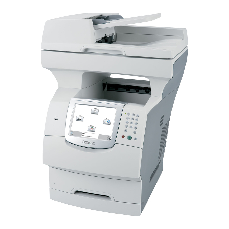
7002-xxx 1. General information The Lexmark™ X642e, X644e, and X646e are All-In-One laser MFPs that provide print, copy, scan, and fax functions designed to attach to IBM-compatible personal computers and most computer networks. The operator panel is touch-sensitive and allows the user to adjust the viewing angle. -
Page 22: Configured Models
7002-xxx Configured models The following illustrations show and compare standard X642e and X644e MFPs and X642e and X644e MFPs configured with a duplex unit and a 500-sheet drawer. Other print media handling options are also available. Model X644e or X646e MFP... -
Page 23: Options
Parallel interface card – MarkNet™ Professional Print Servers—Only one active internal networking connection is supported. Installing an optional Lexmark MarkNet Professional N800 Series internal print server makes the server the active network connection and disables the standard Ethernet port. –... -
Page 24: Specifications
7002-xxx Specifications General MFP specifications Lexmark X642e Lexmark X644e/X646e Scanner Scanner type Color flatbed scanner with ADF Color flatbed scanner with ADF Scanner technology Charge coupled device (CCD) Charge coupled device (CCD) Light sources Two Cold Cathode Fluorescent Lamp Two CCFL and two CCD modules per... -
Page 25: Memory Configuration
7002-xxx Memory configuration Models Memory type Lexmark X642e Lexmark X644e Lexmark X646e Standard DRAM (MB) Optional memory (MB) 128, 256, and 512 available (One slot—100 pin DDR SDRAM unbuffered DIMMs) Maximum (MB) Optional flash memory (MB) 32 and 64 available Hard disk <20GB... -
Page 26: Dimensions
Lexmark X646e 28.0 in. 22.0 in. 25.4 in. 84.5 lb (710 mm) (560 mm) (645 mm) (46.7 kg) Lexmark X646e (with duplex and 35.0 in. 22.0 in. 26.0 in. 103 lb 500-sheet option) (890 mm) (560 mm) (660 mm) (46.7 kg) -
Page 27: Power Requirements
7002-xxx Power requirements Average nominal power requirements for the base printer configuration (110 volt). Power levels are shown in watts (W). Maximum current is given in Amperes (A). Printing states Lexmark X642e Lexmark X644e Lexmark X646e .05 W .05 W Idle—average power... -
Page 28: Environment
7002-xxx Environment Printer temperature and humidity • Operating – Temperature: 16 to 32° C (60° to 90° F) – Relative humidity: 8 to 80% – Altitude: 10,000 ft. (0 to 3,048 meters) • Storage and shipping environment (packaged) – Temperature: -40° to 43° C (-40° to 110° F) –... -
Page 29: Media Specifications
For more details about the types of paper and specialty media your printer supports, refer to the Card Stock & Label Guide available on our Lexmark Web site at www.lexmark.com. We recommend that you try a limited sample of any paper or specialty media you are considering using with the printer before purchasing large quantities. - Page 30 7002-xxx Legend ✓ — indicates support Print media Dimensions size ✓ ✓ ✓ ✓ ✓ ✓ ✓ ✓ Executive 184.2 x 266.7 mm (7.25 x 10.5 in.) ✓ ✓ ✓ ✓ ✓ ✓ ✓ ✓ Folio 216 x 330 mm (8.5 x 13 in.) ✓...
-
Page 31: Print Media Types
7002-xxx Print media types Print media ✓ ✓ ✓ ✓ ✓ ✓ Paper ✓ ✓ ✓ ✓ Card stock ✓ ✓ ✓ ✓ Transparencies ✓ ✓ ✓ ✓ Vinyl labels ✓ ✓ ✓ ✓ Paper labels ✓ ✓ ✓ ✓ Polyester label ✓... - Page 32 Printing label applications on the MFP requires a special label fuser cleaner. Information on whether your vinyl label converter has passed Lexmark criteria is available at the Lexmark Web site (www.lexmark.com); search for “converter list.” You can also check the Lexmark Automated Fax...
-
Page 33: Selecting Print Media
The following paper characteristics affect print quality and reliability. We recommend that you follow these guidelines when evaluating new paper stock. For detailed information, see the Card Stock & Label Guide located on the Lexmark Web site at www.lexmark.com. The laser printing process heats paper to high temperatures of 230°C (446°F). For Magnetic Ink Character Recognition (MICR) applications and for non-MICR applications, use only paper able to withstand these temperatures without discoloring, bleeding, or releasing hazardous emissions. -
Page 34: Transparencies
For detailed information, see the Card Stock & Label Guide, which is available on the Lexmark Web site at www.lexmark.com. Transparencies can be fed automatically from the multipurpose feeder and all standard and optional trays, except the 2000-sheet drawer. -
Page 35: Labels
For detailed information on label printing, characteristics, and design, see the Card Stock & Label Guide available on the Lexmark Web site at www.lexmark.com/publications. Note: Labels are one of the most difficult print media for laser MFPs. All MFP models require a special fuser cleaner for label applications to optimize feed reliability. -
Page 36: Card Stock
7002-xxx Card stock Card stock is single ply, and has a large array of properties, such as the moisture content, thickness, and texture, that can significantly affect print quality. See “Supported print media” on page 1-9 for information on the preferred weight and for the grain direction of print media. -
Page 37: Tools Required
7002-xxx • Keep print media stored in an acceptable environment. See “Storing print media” on page 1-16. • Do not remove trays during a print job. • Push all trays in firmly after loading them. • Make sure the guides in the trays are properly positioned for the size of print media you have loaded. Make sure the guides are not placed too tightly against the stack of print media. -
Page 38: Acronyms
HVPS High Voltage Power Supply Internal Tray Card LASER Light Amplification by Stimulated Emission of Radiation Liquid Crystal Display Light-Emitting Diode Lexmark Embedded Solution (applications) LVPS Low Voltage Power Supply Motor Driver Control Multifunction Printer Multipurpose Feeder NVRAM Nonvolatile Random Access Memory... -
Page 39: Diagnostic Information
7002-xxx 2. Diagnostic information Start CAUTION CAUTION When you see this symbol, there is a danger from hazardous voltage in the area of the product Remove the power cord from the printer or wall outlet before you connect or disconnect any where you are working. -
Page 40: Understanding The Mfp Operator Panel
If a setting cannot be changed from the application, use the MFP operator panel, MarkVision Professional, or the Web pages. Changing a setting from the MFP operator panel, MarkVision Professional, or the Web pages makes that setting the user default. MFP operator panels Model X642e Models X644e/X646e Service Manual... - Page 41 7002-xxx Callout Operator panel item Function A liquid crystal display (LCD) which shows home screen buttons, menus, menu items, and values. Allows for making selections within Copy, Fax, and so on. Indicator light Gives information about the status of the MFP using the colors red and green. Status Indicates MFP power is off.
-
Page 42: Home Screen And Home Screen Buttons
The USB direct interface can also be used to scan a document to a USB flash memory device using the PDF, TIFF, or JPEG formats. Home Returns the LCD to the home screen. (only on model X642e) Help Tips Accesses the context-sensitive Help feature. (only on model X642e) Menu Accesses the menus. - Page 43 For models X644e and X646e, the Menus icon is on a gray bar called the navigation bar. For model X642e, the Menu button is on the left side of the operator panel. See “Menu (only on model X642e)” on page 2-4.
- Page 44 7002-xxx Buttons and touchscreen icon buttons (refer to Menus & Messages for comprehensive list) (continued) Models X644e, Model X642e Button name Function X646e Search Held To search on any of the following items and return any Jobs matches: • User names for held or confidential print jobs •...
- Page 45 If a different value within a menu item is touched, it Submit needs to be saved to become the current user default setting. Submit For model X642e—To save the value as the new user default setting, touch Submit. Back For all models, touch Back to return to the previous screen, and all the settings for the scan job made on Sample screen one are lost.
- Page 46 7002-xxx Buttons and touchscreen icon buttons (refer to Menus & Messages for comprehensive list) (continued) Models X644e, Model X642e Button name Function X646e Up arrow Touch the up arrow to move up to the next item in a list, such as a list of menu items or values.
-
Page 47: Menus
Models X644e/X646e—touch the menu icon in the lower right corner of the home screen • Models X642e—press the menu button ( ) to the left of the operator panel. When a value or setting is selected and saved, it is stored in MFP memory. Once stored, these settings remain active until new ones are stored or the factory defaults are restored. -
Page 48: Symptom Tables
LCD touchscreen icon buttons do not work Go to “LCD touchscreen display service check—models X644e/X646e” on page 2-149. LCD touchscreen (mono—model X642e)— Go to “LCD touchscreen contrast control service check— contrast does not change with contrast model X642e” on page 2-149. -
Page 49: Scanner-Adf Symptoms
7002-xxx Printer symptoms (continued) Symptom Action Printer—vertical black bands on edge of Go to “Print quality—black bands on outer edges of the copy (print quality) page” on page 2-163. Unable to clear a 32-Unsupported Print Go to “Signature button assembly service check” on Cartridge user error message. -
Page 50: Paper Tray Symptoms
7002-xxx Paper tray symptoms Symptom Action Paper feed problem with 250-Sheet Paper Go to “Input tray(s) service check” on page 2-147. Tray. Paper feed problem with 500-Sheet Paper Go to “Input tray(s) service check” on page 2-147. Tray. Media fails to pass through from the lower Go to “Input tray(s) service check”... -
Page 51: Messages And Error Codes
7002-xxx Messages and error codes Service error codes Service error codes are generally non-recoverable except in an intermittent condition when you can POR the printer to temporarily recover from the error condition. Service error codes are indicated by a three-digit error code followed by a period and additional numbers in the format XXX.YY. - Page 52 7002-xxx Service error codes (9xx.xx) Error Display text Description Action code codes RIP Software Go to “900.xx Error code service check” on page 2-118. 947 Modem Init Failed Defective modem hardware. Replace the modem card. Engine flash error Indicates that the flash which the Replace the system board.
- Page 53 7002-xxx Service error codes (9xx.xx) (continued) Error Display text Description Action code codes Hot roll took too long to • Bad thermistor, circuit or cabling. Go to “920.xx—Cold fuser service heat up after check” on page 2-132. • Fuser not receiving sufficient AC transitioning to new power.
- Page 54 7002-xxx Service error codes (9xx.xx) (continued) Error Display text Description Action code codes Hot roll took too long to • Bad thermistor, circuit, or Go to “920.xx—Cold fuser service heat up after cabling. check” on page 2-132. transitioning to new •...
- Page 55 7002-xxx Service error codes (9xx.xx) (continued) Error Display text Description Action code codes Hot roll took too long to • Bad thermistor, circuit, or Go to “920.xx—Cold fuser service heat up after cabling. check” on page 2-132. transitioning to new •...
- Page 56 7002-xxx Service error codes (9xx.xx) (continued) Error Display text Description Action code codes Under temperature • Bad thermistor, circuit, or Go to “920.xx—Cold fuser service during steady state cabling. check” on page 2-132. control. Fuser page • Fuser not receiving AC power. count between 300,000 •...
- Page 57 7002-xxx Service error codes (9xx.xx) (continued) Error Display text Description Action code codes Hot roll took too long to • Bad thermistor, circuit, or Go to “920.xx—Cold fuser service heat up after cabling. check” on page 2-132. transitioning to new •...
- Page 58 7002-xxx Service error codes (9xx.xx) (continued) Error Display text Description Action code codes Hot roll took too long to • Bad thermistor, circuit, or Go to “920.xx—Cold fuser service heat up after cabling. check” on page 2-132. transitioning to new •...
- Page 59 7002-xxx Service error codes (9xx.xx) (continued) Error Display text Description Action code codes Hot roll took too long to • Bad thermistor, circuit, or Go to “920.xx—Cold fuser service heat up after cabling. check” on page 2-132. transitioning to new •...
- Page 60 7002-xxx Service error codes (9xx.xx) (continued) Error Display text Description Action code codes Hot roll took too long to • Low wattage or incorrect lamp. Go to “922.xx—Cold fuser check” reach the beginning on page 2-134. • Bad thermistor, circuit, or lamp detection cabling.
- Page 61 7002-xxx Service error codes (9xx.xx) (continued) Error Display text Description Action code codes Hot roll timed out in • Low wattage or incorrect lamp. Go to “922.xx—Cold fuser check” trying to reach the final on page 2-134. • Bad thermistor, circuit, or lamp detection cabling.
- Page 62 7002-xxx Service error codes (9xx.xx) (continued) Error Display text Description Action code codes Hot roll did not reach • Low wattage or incorrect lamp. Go to “922.xx—Cold fuser check” operating temperature in on page 2-134. • Bad thermistor, circuit, or time (new enhanced cabling.
- Page 63 7002-xxx Service error codes (9xx.xx) (continued) Error Display text Description Action code codes Hot roll took too long to • Low wattage or incorrect lamp. Go to “922.xx—Cold fuser check” reach the beginning on page 2-134. • Bad thermistor, circuit, or lamp detection cabling.
- Page 64 7002-xxx Service error codes (9xx.xx) (continued) Error Display text Description Action code codes Hot roll reached final • Low wattage or incorrect lamp. Go to “922.xx—Cold fuser check” lamp detection on page 2-134. • Bad thermistor, circuit, or temperature but took cabling.
- Page 65 7002-xxx Service error codes (9xx.xx) (continued) Error Display text Description Action code codes Hot roll timed out in • Low wattage or incorrect lamp. Go to “922.xx—Cold fuser check” trying to reach the final on page 2-134. • Bad thermistor, circuit, or lamp detection cabling.
- Page 66 7002-xxx Service error codes (9xx.xx) (continued) Error Display text Description Action code codes Fuser over temperature. • Short in the thermistor circuit. Go to “923.xx—Hot fuser service Fuser page count check” on page 2-135. • Noisy thermistor signal stopped at 500,000 to •...
- Page 67 7002-xxx Service error codes (9xx.xx) (continued) Error Display text Description Action code codes Lamp detection • 115 V lamp in 220 V printer. Go to “925.xx—Hot fuser service performed and found check” on page 2-137. • Lamp has excessive wattage. error.
- Page 68 7002-xxx Service error codes (9xx.xx) (continued) Error Display text Description Action code codes Too hot to do lamp Attempting to POR machine after Go to “925.xx—Hot fuser service detection and NVRAM receiving a 925.01. check” on page 2-137. bit indicates previous wrong lamp detected.
- Page 69 7002-xxx Service error codes (9xx.xx) (continued) Error Display text Description Action code codes Main fan capture data is Corrupted feedback signal. Go to “Main fan service check” on invalid and speed page 2-119. control is at maximum in fan control adjustment state.
- Page 70 7002-xxx Service error codes (9xx.xx) (continued) Error Display text Description Action code codes No lock detected at • Check for paper jams Go to “Main drive service check” motor start for motor ID. on page 2-153. • Gear binds Motor is type 0. •...
- Page 71 7002-xxx Service error codes (9xx.xx) (continued) Error Display text Description Action code codes Loss of lock detected by • Defective motor cable Go to “Main drive service check” higher level code. Motor on page 2-153. • Defective main drive motor is type 1.
- Page 72 7002-xxx Service error codes (9xx.xx) (continued) Error Display text Description Action code codes Replace the system board. See “System board and inner shield removal —models X644e/X646e” on page 4-131. Warning: When replacing any one of the following components: • Flatbed interconnect card •...
- Page 73 7002-xxx Service error codes (9xx.xx) (continued) Error Display text Description Action code codes .30— Service NVRAM EPROM mismatch failure This error code indicates a mismatch mismatch between the System Board assembly and the interface card assembly. Warning: In the event of replacement of any one of the following components: •...
- Page 74 7002-xxx Service error codes (9xx.xx) (continued) Error Display text Description Action code codes Replace the interface card. See “Interface card assembly removal” on page 4-107. Warning: When replacing any one of the following components: • Flatbed interconnect card • System board assembly •...
- Page 75 7002-xxx Service error codes (9xx.xx) (continued) Error Display text Description Action code codes Unreliable The engine is experiencing Service errors 980 thru 984 communications to unreliable communications to the <device> can be one of the Paperport device specified device. following: system board, duplex, tray x (1, 2, 3, 4, or 5), envelope feeder or output bin.
-
Page 76: User Status Displays
7002-xxx User status displays. User status displays Display text Description/action Code code Bin [x] Full x represents the number of the output bin that is full when the MFP bins are linked. Remove print media from the bins. The message clears once the output level of the linked bins is no longer full. - Page 77 7002-xxx User status displays (continued) Display text Description/action Code code Parallel A parallel interface is the active communication link. Parallel [x] Notes: • The current interface appears on the Menu Settings Page. Interfaces shown without an x or y means the active host interface is a standard interface.
- Page 78 7002-xxx User status displays (continued) Display text Description/action Code code Ready The MFP is ready to receive and process jobs. Print, fax, scan, e-mail, copy, or use FTP. Scanner automatic The automatic document feeder (ADF) cover is open. document feeder Close the cover.
- Page 79 7002-xxx User status displays (continued) Display text Description/action Code code Answering The MFP is answering a fax call. Call complete A fax call is completed. Connect <x>bps The fax is connected. <x> is the baud rate per second. Dialing A fax number is dialed. If the number is too long to fit on the screen only the word Dialing appears.
-
Page 80: User Attendance Messages
7002-xxx User attendance messages User attendance messages Code Primary message Description/action code Change Cartridge Select one of the following actions: Invalid Refill Remove the toner cartridge and install a new cartridge. Change [src] to Lets the user override the current print media source for the remainder of [Custom String] the print job. - Page 81 7002-xxx User attendance messages (continued) Code Primary message Description/action code Check Duplex This messages displays for the following conditions: Connection • The duplex option may have been removed from the printer, possibly to clear a paper jam or to remove the option. •...
- Page 82 7002-xxx User attendance messages (continued) Code Primary message Description/action code Clean scanner During a scanner calibration, the firmware detects that the scanner ADF or glass flatbed glass may be dirty. Touch Cancel Job if a scan job is processing when the attendance message appears.
- Page 83 7002-xxx User attendance messages (continued) Code Primary message Description/action code Install Duplex This message is displayed when a duplex option has been hot unplugged. or Cancel Job The printer requires the reinstallation of the option to print a page which has been formatted by the interpreter before the option was removed.
- Page 84 7002-xxx User attendance messages (continued) Code Primary message Description/action code Load manual feeder Occurs when the MFP receives a manual feed request that specific print with [Custom Type media be loaded into the multipurpose feeder. The print media is previously Name] defined as a custom type from Custom 1 through Custom 6.
- Page 85 7002-xxx User attendance messages (continued) Code Primary message Description/action code Load [src] with Occurs when a source is loaded with an incorrect print media size as [size] specified in the Paper Menu. Touch Continue. Load the specified source that is set for the requested size.
- Page 86 7002-xxx User attendance messages (continued) Code Primary message Description/action code Reattach This messages displays for the following conditions: Envelope Feeder • The feeder may have been removed from the printer, possibly to clear a paper jam or to remove the option. •...
- Page 87 7002-xxx User attendance messages (continued) Code Primary message Description/action code Replace all One or more messages which interrupted a scan job are now cleared. originals if Replace the original documents in the scanner to restart the scan job. restarting job. Touch Cancel Job if a scan job is processing when the attendance message appears.
- Page 88 Touch Continue to clear the message. Some held jobs are not restored. They stay on the hard disk and are inaccessible. Invalid refill, The MFP detects a refilled Lexmark Cartridge Return Program print change cartridge cartridge. Install a new print cartridge to clear the message.
- Page 89 7002-xxx User attendance messages (continued) Code Primary message Description/action code Insufficient The MFP cannot defragment flash memory because the memory used to memory for Flash store undeleted flash resources is full. Memory Defragment Touch Continue to clear the message. operation To perform the defragment operation, install additional memory, or delete fonts, macros, and other data to free some memory space.
- Page 90 7002-xxx User attendance messages (continued) Code Primary message Description/action code Printer/cartridge Cartridge region code does not match MFP region code. mismatch x=printer region and y=cartridge region. The following regions may be listed: Code Region Worldwide USA and Canada Europe, Middle East, and Africa Asia Latin America Undefined region...
- Page 91 7002-xxx User attendance messages (continued) Code Primary message Description/action code Serial option [x] The MFP detects a serial error, such as framing, parity, or overrun on the error specified optional serial port. x is the number of the optional serial port. •...
- Page 92 7002-xxx User attendance messages (continued) Code Primary message Description/action code Too many disks Model X646e only. The MFP detects an excess of hard disks installed. installed 1. Turn the MFP off. 2. Unplug the power cord from the wall outlet. 3.
- Page 93 7002-xxx User attendance messages (continued) Code Primary message Description/action code Disk full Model X646e only. The MFP detects that there is not enough memory or space on the hard disk to store the data of the print job. Touch Continue to clear the message and continue processing the current print job.
-
Page 94: User Line 2 Link Messages
7002-xxx User line 2 link messages If the printer is locked on a particular link, the link indication displays. If the printer is ready to process any link, no messages display. Link messages are listed in the following table. User message Explanation Parallel Standard Parallel Port, if available. -
Page 95: User Attendance Messages-Paper Jams And Paper Handling Errors (2Xx.xx)
7002-xxx User attendance messages—paper jams and paper handling errors (2xx.xx) When the printer jams, the appropriate jam message will be displayed on the printer operator panel. If you select Show Areas on the operator panel, you can view one or more images to help you clear the jam. User attendance messages—paper jams and paper handling errors (2xx.xx) Code Description... - Page 96 7002-xxx User attendance messages—paper jams and paper handling errors (2xx.xx) Code Description Possible causes Action code Option tray never picked Fail to feed from option. Possible causes • Fan media and stack flat in a page. may include media edge locking, worn or tray or MPF.
- Page 97 7002-xxx User attendance messages—paper jams and paper handling errors (2xx.xx) Code Description Possible causes Action code Main drive motor error Main drive motor not working. • Make sure paper path is possibly due to clear High mechanical load due to paper jam mechanical load.
- Page 98 7002-xxx User attendance messages—paper jams and paper handling errors (2xx.xx) Code Description Possible causes Action code Expected wide page not • Page did not enter or exit fuser nip • If label media, ensure front detected by narrow cleanly. edge meets 1/16 inch media sensor, possible requirement.
- Page 99 7002-xxx User attendance messages—paper jams and paper handling errors (2xx.xx) Code Description Possible causes Action code Expected wide page not • Page did not enter or exit fuser nip • If label media, ensure front detected by narrow cleanly. edge meets 1/8 inch media sensor, possible requirement.
- Page 100 7002-xxx User attendance messages—paper jams and paper handling errors (2xx.xx) Code Description Possible causes Action code Expected wide page not • Page did not enter or exit fuser nip • If label media, ensure front detected by narrow cleanly. edge meets 1/8 inch media sensor, possible requirement.
- Page 101 7002-xxx User attendance messages—paper jams and paper handling errors (2xx.xx) Code Description Possible causes Action code Expected wide page not • Page did not enter or exit fuser nip • If label media, ensure front detected by narrow cleanly. edge meets 1/8 inch media sensor, possible requirement.
- Page 102 7002-xxx User attendance messages—paper jams and paper handling errors (2xx.xx) Code Description Possible causes Action code Expected wide page not • Page did not enter or exit fuser nip • If label media, ensure front detected by narrow cleanly. edge meets 1/8 inch media sensor, possible requirement.
- Page 103 7002-xxx User attendance messages—paper jams and paper handling errors (2xx.xx) Code Description Possible causes Action code Expected wide page not • Page did not enter or exit fuser nip • If label media, ensure front detected by narrow cleanly. edge meets 1/8 inch media sensor, possible requirement.
- Page 104 7002-xxx User attendance messages—paper jams and paper handling errors (2xx.xx) Code Description Possible causes Action code Expected wide page not • Page did not enter or exit fuser nip • If label media, ensure front detected by narrow cleanly. edge meets 1/8 inch media sensor, possible requirement.
- Page 105 7002-xxx User attendance messages—paper jams and paper handling errors (2xx.xx) Code Description Possible causes Action code Page did not cleanly exit Page may be jammed in fuser exit or • Make sure the redrive door fuser or redrive area. redrive area. is complete closed.
- Page 106 7002-xxx User attendance messages—paper jams and paper handling errors (2xx.xx) Code Description Possible causes Action code Exit sensor bounced. Exit sensor assembly. Go to “Fuser exit sensor Fuser page count service check” on between 0 and 99,999. page 2-138. Never sent the divert command to the stacker.
- Page 107 7002-xxx User attendance messages—paper jams and paper handling errors (2xx.xx) Code Description Possible causes Action code Page did not cleanly exit Page may be jammed in fuser exit or • Make sure the redrive door fuser or redrive area. redrive area. is complete closed.
- Page 108 7002-xxx User attendance messages—paper jams and paper handling errors (2xx.xx) Code Description Possible causes Action code Exit sensor bounced. Exit sensor assembly. Go to “Fuser exit sensor Fuser page count service check” on between 100,000 and page 2-138. 199,999. Never sent the divert command to the stacker.
- Page 109 7002-xxx User attendance messages—paper jams and paper handling errors (2xx.xx) Code Description Possible causes Action code Page did not cleanly exit Page may be jammed in fuser exit or • Make sure the redrive door fuser or redrive area. redrive area. is complete closed.
- Page 110 7002-xxx User attendance messages—paper jams and paper handling errors (2xx.xx) Code Description Possible causes Action code Exit sensor may have Exit sensor assembly Go to “Fuser exit sensor bounced. Fuser page service check” on count between 200,000 page 2-138. and 299,999. Never sent the divert command to the stacker.
- Page 111 7002-xxx User attendance messages—paper jams and paper handling errors (2xx.xx) Code Description Possible causes Action code Page did not cleanly exit Page may be jammed in fuser exit or • Make sure the redrive door fuser or redrive area. redrive area. is complete closed.
- Page 112 7002-xxx User attendance messages—paper jams and paper handling errors (2xx.xx) Code Description Possible causes Action code Exit sensor may have Exit sensor assembly. Go to “Fuser exit sensor bounced. Fuser page service check” on count between 300,000 page 2-138. and 399,999. Never sent the divert command to the stacker.
- Page 113 7002-xxx User attendance messages—paper jams and paper handling errors (2xx.xx) Code Description Possible causes Action code Page did not cleanly exit Page may be jammed in fuser exit or • Make sure the redrive door fuser or redrive area. redrive area. is complete closed.
- Page 114 7002-xxx User attendance messages—paper jams and paper handling errors (2xx.xx) Code Description Possible causes Action code Exit sensor may have Exit sensor assembly Go to “Fuser exit sensor bounced. Fuser page service check” on count between 400,000 page 2-138. and 499,999. Never sent the divert command to the stacker.
- Page 115 7002-xxx User attendance messages—paper jams and paper handling errors (2xx.xx) Code Description Possible causes Action code Page did not cleanly exit Page may be jammed in fuser exit or • Make sure the redrive door fuser or redrive area. redrive area. is complete closed.
- Page 116 7002-xxx User attendance messages—paper jams and paper handling errors (2xx.xx) Code Description Possible causes Action code Exit sensor may have Exit sensor assembly. Go to “Fuser exit sensor bounced. Fuser page service check” on count stopped at page 2-138. 500,000 to preserve data.
- Page 117 7002-xxx User attendance messages—paper jams and paper handling errors (2xx.xx) Code Description Possible causes Action code Page did not cleanly exit Page may be jammed in the fuser exit or • Make sure the redrive door fuser or redrive area. redrive area.
- Page 118 7002-xxx User attendance messages—paper jams and paper handling errors (2xx.xx) Code Description Possible causes Action code Exit sensor may have Exit sensor assembly. Go to “Fuser exit sensor bounced. Fuser page service check” on count is not available. page 2-138. Never sent the divert command to the stacker.
- Page 119 7002-xxx User attendance messages—paper jams and paper handling errors (2xx.xx) Code Description Possible causes Action code Paper did not clear the • Duplex rear door not fully latched. • Make sure the duplex duplex input sensor but assembly rear door is •...
- Page 120 7002-xxx User attendance messages—paper jams and paper handling errors (2xx.xx) Code Description Possible causes Action code Paper did not leave the • Duplex jam access tray is not fully • Make sure the duplex jam duplex exit sensor. latched. access tray is installed correctly •...
- Page 121 7002-xxx User attendance messages—paper jams and paper handling errors (2xx.xx) Code Description Possible causes Action code Duplex exit sensor • Media left in the duplex and • Remove any sheets from covered. Continue selected. the duplex option. • Sensor is having mechanical or •...
- Page 122 7002-xxx User attendance messages—paper jams and paper handling errors (2xx.xx) Code Description Possible causes Action code Duplex did not send • Mechanical feed error due to belt Replace the duplex option. Device Controls slipping. response. • Timing error due to feed system. Duplex did not send •...
- Page 123 7002-xxx User attendance messages—paper jams and paper handling errors (2xx.xx) Code Description Possible causes Action code Page did not reach input If source is tray 1, possible causes • Fan media. sensor. include: • Turn media over. • Edge locking •...
- Page 124 7002-xxx User attendance messages—paper jams and paper handling errors (2xx.xx) Code Description Possible causes Action code Failed to feed from • Paper jam tray 1. Pages in the • Worn pick tires. paper path have been flushed to the output bin. Not applicable to tray 1.
- Page 125 7002-xxx User attendance messages—paper jams and paper handling errors (2xx.xx) Code Description Possible causes Action code Paper over tray 2 pass • Paper left in path • Clear media jams. thru sensor on warm-up. • Failed pass thru sensor • Check/replace pass thru sensor.
- Page 126 7002-xxx User attendance messages—paper jams and paper handling errors (2xx.xx) Code Description Possible causes Action code Fail to feed from tray 3 Failure to feed. Possible causes include: • Clear media jams. • Edge locking • Replace pick tires. See “Integrated tray •...
- Page 127 7002-xxx User attendance messages—paper jams and paper handling errors (2xx.xx) Code Description Possible causes Action code Option tray pass thru Paper jam • Clear all jams. sensor never became Failed sensor • Check/replace pass thru uncovered. sensor. Failed to pick from tray 4 •...
- Page 128 7002-xxx User attendance messages—paper jams and paper handling errors (2xx.xx) Code Description Possible causes Action code Option tray pass thru Failure to feed. Possible causes include: • Clear media jams. sensor never became • Edge locking • Replace pick tires. See covered.
- Page 129 7002-xxx User attendance messages—paper jams and paper handling errors (2xx.xx) Code Description Possible causes Action code Page did not reach input Paper jam around the multipurpose tray. • Check for jam in tray. sensor. • Check pick assembly and controller card. Page was not properly Paper jam around the multipurpose •...
- Page 130 7002-xxx User attendance messages—paper jams and paper handling errors (2xx.xx) Code Description Possible causes Action code Paper in envelope feeder on warm-up. Page was not properly Paper jam around envelope feeder. • Remove feeder and clear picked from envelope jam. feeder.
- Page 131 7002-xxx User attendance messages—paper jams and paper handling errors (2xx.xx) Code Description Possible causes Action code Paper Missing Jam An attempt was made to force an ADF Make sure the media is loaded scan, by a custom job, page level jam in the ADF when starting an recovery, or so on, with no paper in the ADF scan.
- Page 132 7002-xxx User attendance messages—paper jams and paper handling errors (2xx.xx) Code Description Possible causes Action code Scanner Missing—Rear One of the cables on the rear of the Check the cables on the rear of Side Cable Unplugged scanner is unplugged or loose. the scanner to make sure they are plugged in and fastened securely.
-
Page 133: Service Checks
7002-xxx Service checks Anytime the system board is replaced, the Configuration ID must be reset in NVRAM. Go to “Configuration ID” on page 3-19. Review the following information before performing any service checks. • Paper feed problems (especially paper jams): Go to “Display Log”... -
Page 134: Error Code Service Check
7002-xxx 290.00 Error code service check Static jam—ADF interval sensor (A). Note: Before starting this service check, make sure the interval sensor cable is correctly installed. Action Check for any signs of paper or other debris that might be present in the ADF assembly over the interval sensor. - Page 135 7002-xxx Action Interval sensor—electrical Turn the power off and reconnect CN10 to the motor driver card. checks Measure the voltages in the table below with the sensor in normal operation (sensor closed) and with the sensor open (paper over the sensor).
- Page 136 7002-xxx 290.01 Error code service check ADF pickup jam. Note: Before starting this service check, make sure the interval sensor (A) cable is correctly installed. Action Pickup arm assembly Check to make sure the pickup arm is correctly installed. If not installed correctly, reinstall properly.
- Page 137 7002-xxx Action ADF feed motor Check the ADF feed motor for proper operation. Turn the power off, disconnect CN2 on the motor driver card, and measure the voltages on CN2. ADF feed motor Connector CN2 (motor driver card) Pin number Static Operating CN2—Pin 1...
-
Page 138: Error Code Service Check
7002-xxx 290.02 Error code service check ADF feed jam. Note: Before starting this service check, make sure the first scan sensor (A) cable is correctly installed. Action Check for any signs of paper or other debris that might be present in the ADF assembly over the interval sensor but short of the first scan sensor. - Page 139 7002-xxx Action First scan sensor— Turn the power off and reconnect CN10 to the motor driver card. electrical checks Measure the voltages in the table below with the sensor in normal operation (sensor closed) and with the sensor open (paper over the sensor).
- Page 140 7002-xxx 290.10 Error code service check Static jam—first scan sensor (A) Note: Before starting this service check, make sure the first scan sensor cable is correctly installed. Action Check for any signs of paper or other debris that might be present in the ADF assembly over the first scan sensor.
- Page 141 7002-xxx Action First scan sensor— Turn the power off, and reconnect CN10 to the motor driver card. electrical checks Measure the voltages in the table below with the sensor in normal operation (sensor closed) and with the sensor open (paper over the sensor).
- Page 142 7002-xxx 291.00 Error code service check Static jam—second scan sensor (A). Note: Before starting this service check, make sure the second scan sensor cable is correctly installed. Action The media is jammed or stuck in the ADF at the second scan sensor. Check for any signs of paper or other debris that might be present or jammed in the ADF assembly around the second scan sensor.
-
Page 143: Error Code Service Check
7002-xxx Action Second scan sensor— Turn the power off, and reconnect CN9 to the motor driver card. electrical checks Measure the voltages in the table below with the sensor in normal operation (sensor closed) and with the sensor open (sensor flag activated). - Page 144 7002-xxx 291.02 Error code service check Second ADF scan sensor (A) jam. Note: Before starting this service check, make sure the sensor cable is correctly installed. Action The second scan sensor has detected the leading edge of the sheet but did not detect the training edge. The first scan sensor detected the leading edge.
- Page 145 7002-xxx Action Motor driver card Turn the power off, and disconnect CN9 on the motor driver card. Measure the voltages in the table below: Second scan sensor—reflective type (normally closed) Connector CN9 (motor driver card) CN9—Pin 4 0 V dc CN9—Pin 5 +5 V dc CN9—Pin 6...
- Page 146 7002-xxx 293 Error code service check Paper missing jam. Note: Before starting this service check, make sure the sensor cable is correctly installed. Action Check the ADF for any media that might be jammed in the ADF. Turn the MFP off and then back on. Feed several sheets of media through the ADF.
- Page 147 7002-xxx 294.00 Error code service check Static jam—ADF exit sensor (A). Before starting this service check, Check the ADF exit sensor cable for correct installation. Action ADF—jammed media Check for any signs of media or other debris that might be present in the ADF assembly around the exit sensor flag.
- Page 148 7002-xxx Action ADF exit sensor—electrical Turn the power off, and reconnect CN9 to the motor driver card. checks Measure the voltages in the table below with the sensor in normal operation (sensor closed) and the sensor open (sensor flag activated). ADF exit sensor—interrupter type (normally closed) Connector CN9 (motor driver card) Pin number...
- Page 149 7002-xxx Action ADF exit sensor flag Check the exit sensor flag to make sure it operates freely and does not hang or bind. If the flag does not operate correctly and cannot be made to operate correctly, replace the complete ADF assembly. See “ADF complete assembly removal”...
- Page 150 7002-xxx 294.02 Error code service check ADF exit jam sensor (A) off. Note: Before starting this service check, make sure the sensor cable is installed correctly. Action ADF—jammed media Check for any signs of media or other debris that might be present in the ADF assembly around the exit sensor flag.
- Page 151 7002-xxx Action ADF exit sensor—electrical Turn the power off, and reconnect CN9 to the motor driver card. checks Measure the voltages in the table below with the sensor in normal operation (sensor closed) and with the sensor open (sensor flag activated).
- Page 152 7002-xxx Action ADF exit sensor flag Check the exit sensor flag to make sure it operates freely and does not hang or bind. If the flag does not operate correctly and cannot be made to operate correctly, replace the complete ADF assembly. See “ADF complete assembly removal”...
-
Page 153: 842.Xx Error Code Service Check
7002-xxx 298.01 Error code service check—models X644e/X646e Scanner missing—front side cable unplugged.This is the ADF CCD 36 pin ICC cable connected to the ADF CCD. Action ADF CCD cable Check the cable for correct connections to the flatbed interface connector on the rear of the flatbed scanner assembly and to the ADF CCD assembly. - Page 154 7002-xxx 843.xx Error code service check Service Scanner—flatbed mechanical failure Other symptoms may include a loud noise from between the flatbed and the printer unit, or a blue screen on the display. Note: Check for correct installation of the home sensor cable before proceeding with this service check. Action Flatbed scanner CCD drive Check to make sure that both of the CCD drive shafts are correctly...
-
Page 155: 845.00 Error Code Service Check
7002-xxx Action Mechanical interference Check for mechanical interference with the flatbed CCD assembly with the flatbed CCD and the metal locating bracket. Remove the glass slit. See “Scanner assembly flatbed glass holder assembly removal” on page 4-50. The bracket is located near the home position, to the left side of the flatbed. -
Page 156: 848.01 Error Code Service Check
With Error Code 900 displayed, press and 2. Record the complete list of Sub Error Codes on the display, then call your next level of support or call Lexmark. 900.90 Error code service check Service scanner—This error indicates defective modem hardware. -
Page 157: 927.Xx Fan Service Check
7002-xxx 927.xx Fan service check 927.xx can be used for the main fan or the cartridge fan. • Main fan—927.00, 927.01, and 927.03 through 927.07. • Cartridge fan—927.02 Main fan service check Service tip: The main fan runs at full speed at the end of POR or when the printer is printing. It will only run half speed when the printer is in the Ready state and not printing. -
Page 158: 950.00 Through 950.29 Eprom Mismatch Failure
7002-xxx 950.00 through 950.29 EPROM mismatch failure Warning: When replacing any one of the following components: • Flatbed interconnect card (ICC) • System board assembly • Interface card assembly Only replace one component at a time. Replace the required component, and perform a POR before replacing a second component listed above. -
Page 159: 950.30 Through 950.60 Eprom Mismatch Failure
Corresponds to P/N… Lexmark X642e (003, 004, 005, 006) M010 6030 40X3310 Lexmark X644e/X646e (001, 002, 011, 012, 101, 102, 111, 112) M010 6000 40X2722 This error code indicates a mismatch between the system board and the interface card. Action... -
Page 160: Adf Paper Length Sensor Service Check-Models X644E/X646E
7002-xxx Action System board Replace the original system board with a new and not previously installed system board. If the problem remains, contact the next level of support. ADF paper length sensor service check—models X644e/X646e Note: There are two cables between the motor driver card and the paper length sensor. Check to make sure both cables are installed correctly. -
Page 161: Adf Paper Width Sensor Service Check-Models X644E/X646E
7002-xxx ADF paper width sensor service check—models X644e/X646e Note: There are two cables between the motor driver card and the paper width sensor. Check to make sure both cables are installed correctly. Action ADF paper tray Enter the Diagnostics Menu (turn on MFP while holding 3 and 6), select SCANNER TESTS, and select Sensor Tests. -
Page 162: Cover Closed Sensors Service Check-Flatbed
7002-xxx Cover closed sensors service check—flatbed Note: Check for correct installation of the sensor cable before proceeding with this service check. Note: Both the cover closing sensor (A) and the cover closed (B) sensor are located in the ADF assembly. Action Flatbed cover closing and Enter the Diagnostics Menu (turn on MFP while holding 3 and 6),... -
Page 163: Cover Closed Switch/Cable Service Check-Printer
7002-xxx Cover closed switch/cable service check—printer Action Toner cartridge Make sure the toner cartridge is correctly installed and that the right and left cartridge tracks are not loose or broken. Make sure the cover closed switch activation tab on the toner cartridge is not broken and that the tab correctly activates the cover closed switch spring. - Page 164 7002-xxx Action +5 V dc test point on the Check for approximately +5 V dc at the +5 V test point on the system system board board. Note: Use care not to short adjacent voltage test points. If the voltage is correct, Go to step 9. If the voltage is incorrect, go to step 4.
-
Page 165: Duplex Option Service Check
7002-xxx Action System board Replace the following FRUs in the order shown one at a time in until the problem is fixed: Scanner control card • Scanner control card. See “Scanner control card removal” on Interface card page 4-48. • System board. See “System board and inner shield removal —models X644e/X646e”... - Page 166 7002-xxx displays 231.xx Jam Action Fuser exit sensor Check the sheet of media is leaving the exit sensor in the fuser and feeding properly into the duplex option. Check the duplex link for correct operation and any signs of damage. If the problem is prior to the duplex input sensor and in the base machine, repair as necessary.
-
Page 167: Envelope Feeder Service Check
7002-xxx Envelope feeder service check Service tip: Check the envelope feeder paper path for any debris, pieces of envelope and so on. If any other options are installed make sure they are operating normally. If only the envelope feeder is failing to operate correctly, continue with this service check, otherwise verify the interconnect card is functioning properly. - Page 168 7002-xxx Touchscreen displays after attempted feed but before envelopes are 260.xx Paper Jam put in the hopper OR the touchscreen continues to display after Load Envelopes envelopes are placed in the hopper Service tip: The kick rolls rotate during the attempted feed cycles. Action Envelope out hopper Check the envelope out sensor flag for damage, correct installation...
-
Page 169: Flatbed Size Sensor Service Check
7002-xxx 260.xx Paper Jam displays, envelope stops in feeder paper path Action Kick rolls/feed rolls/drive Check all the rolls for oil, grease, or other contamination. If you find a rolls problem, clean the rolls. If this does not correct the problem, replace the envelope feeder. -
Page 170: Fuser Service Checks
7002-xxx Fuser service checks 920.xx—Cold fuser service check Error codes 920.x and 922.xx may display for a cold fuser failure. Some 920.xx error codes may be cleared by turning the printer on and off and allowing it to complete POR. CAUTION There is a danger from hazardous voltage in the area of the product where you are working. - Page 171 7002-xxx Action Fuser lamp Check continuity of the fuser to fuser AC cable, fuser top cover assembly, and fuser lamp by checking the continuity between the two Fuser top cover assembly pins on the fuser lamp AC cable connector: Fuser connect cable (fuser •...
-
Page 172: 922.Xx-Cold Fuser Check
7002-xxx 922.xx—Cold fuser check Error codes 920.xx and 922.xx may display for a cold fuser failure. Some 920.xx error codes may be cleared by turning the printer on and off and allowing it to complete POR. CAUTION There is a danger from hazardous voltage in the area of the product where you are working. Unplug the product before you begin, or use caution if the product must receive power in order to perform the task. -
Page 173: 923.Xx-Hot Fuser Service Check
7002-xxx Action Fuser top cover assembly Check to make sure that the thermistor is installed correctly to J5 on (thermistor, thermistor the fuser control card. If installed correctly check the cable for any cable) signs of damage. If any problems are found, replace the fuser top cover assembly.“Fuser narrow media sensor removal”... -
Page 174: Xx—Hot Fuser Service Check
7002-xxx 924.xx—Hot fuser service check Error Code 923.xx, 924.xx, and 925.xx may display for a hot fuser failure. CAUTION The fuser may be hot, use caution before removing or servicing. CAUTION There is a danger from hazardous voltage in the area of the product where you are working. Unplug the product before you begin, or use caution if the product must receive power in order to perform the task. -
Page 175: 925.Xx-Hot Fuser Service Check
7002-xxx 925.xx—Hot fuser service check Error Code 923.xx, 924.xx, and 925.xx may display for a hot fuser failure. CAUTION The fuser may be hot, use caution before removing or servicing. CAUTION There is a danger from hazardous voltage in the area of the product where you are working. Unplug the product before you begin, or use caution if the product must receive power in order to perform the task. -
Page 176: Fuser Exit Sensor Service Check
7002-xxx Fuser exit sensor service check If any of the following codes are displayed, there is a potential problem in the area of the exit sensor: 201.00, 201.02, 201.10, 201.12, 201.22, 201.30, 201.32, 201.40, 201.41, 201.42, 201.50, 201.52, 201.92, 202.00, 202.02, 202.04, 202.10, 202.11, 202.12, 202.14, 202.20, 202.21, 202,22, 202.24. -
Page 177: Fuser Narrow Media Sensor Service Check
7002-xxx Fuser narrow media sensor service check If any of the following error codes are displayed, a problem may exist in the area of the narrow media sensor assembly: 201.04, 201.14, 201.24, 201.34, 201.44, 201.54, and 201.94. Fuser exit and fuser narrow media sensor status check Printer printing—media over Printer not printing—... -
Page 178: Fuser Solenoid Service Check
“Low voltage power supply removal” on page 4-109. If correct, replace the system board. See “System board and inner shield removal—model X642e” on page 4-130 “System board and inner shield removal —models X644e/ X646e” on page 4-131. Fuser board to system... -
Page 179: High-Capacity Feeder Input Tray Service Check
7002-xxx High-capacity feeder input tray service check Note: Voltage measurements in the high-capacity feeder input tray service checks must be made with the high- capacity feeder attached to the printer to obtain accurate results. Service tip: Be sure the paper size switch is set to the correct paper size setting and the rear paper guides are in the correct locations for the size of paper installed in the high-capacity feeder tray. - Page 180 7002-xxx Action High-capacity feeder option Check the voltage on J8-1 (green). The voltage measures +24 V dc. control board If incorrect, check the autoconnect system for any problems. +24 V dc must come from the printer through the autoconnect system to the high-capacity input for the high-capacity feeder to be recognized.
- Page 181 7002-xxx displays when there is paper in the high-capacity feeder input tray Tray x Empty Action Paper out sensor flag Check the paper out sensor flag for correct operation and installation. If correct, replace the high-capacity feeder system board. (The paper out sensor is mounted on the high-capacity feeder system board.) Paper out sensor (on option system board)
- Page 182 7002-xxx The elevator tray does not move up or down; the printer recognizes that the option is installed Action DC drive motor high- Be sure the motor cable is correctly installed at J1 on the board. capacity feeder option Check the cables, damaged or loose wires. Disconnect the motor. system board Check for a short between each pin and the motor housing.
- Page 183 7002-xxx Paper size switch not selecting paper size that is selected Action Paper size switch Check for continuity between the common pin (J5-1) and the pin of High-capacity feeder option the paper size selected. control board Color Paper size J5-1 Black Common lead J5-2...
-
Page 184: Input Sensor Service Check
7002-xxx displays when the high-capacity feeder input tray is full or has Tray x Paper Low adequate paper in the tray Action Paper low switch Run the sensor diagnostics for tray x (x=the number that represents the high-capacity input tray). Paper low switch cable High-capacity feeder option If the test fails, check the voltage at J3-1 (gray). -
Page 185: Input Tray(S) Service Check
7002-xxx Input tray(s) service check Optional 250-sheet and 500-sheet trays Service tip: Try all the other input paper sources to make sure they are properly feeding paper. For 990 Error Code- Service Tray x, x= displays the number of the tray that has a problem or needs service. Action Tray x Option system board Check the autoconnect cables and connectors for damage. -
Page 186: Interface Card Service Check
7002-xxx displays when tray x has paper in the tray Tray x Empty Action Paper out sensor flag Check the paper out sensor flag for correct operation and installation. If correct, replace the option system board. (The paper out sensor is mounted on the system board). -
Page 187: Lcd Touchscreen Contrast Control Service Check-Model X642E
7002-xxx LCD touchscreen contrast control service check—model X642e Note: If the contrast control only works over part of its travel, replace the left operator panel cover assembly. “Operator panel left cover assembly removal” on page 4-61. Action UICC card #1 to UICC... - Page 188 7002-xxx Action LCD inverter card Check the voltages at CN1-1 and CN1-2. LCD Touchscreen display Connector CN1 (LCD inverter card) Operator panel right cover Display dark Display lit assembly CN1–1 Power +12 V dc +12 V dc LCD touchscreen display CN1–2 Power +12 V dc +12 V dc...
- Page 189 7002-xxx LCD touchscreen backlight—models X644e/X646e Unable to change LCD touchscreen backlight. Action Inverter card 8-pin cable Check to make sure the cable is installed correctly to the inverter card and to the operator panel card. Inverter card 8-pin cable Check continuity of the 8-pin inverter card cable. If correct, go to step 3.
- Page 190 7002-xxx LCD touchscreen display lights up, icons displayed, but it does not work when touched. Action LCD touchscreen display/ Check the 4-pin display to operator panel card cable for correct 4-pin cable installation to J3 on the operator panel card. Note: This cable is a short ribbon cable that can easily become disconnected from J3 on the operator panel card.
-
Page 191: Main Drive Service Check
7002-xxx Main drive service check Service tip: Excessive gear or main drive assembly noise is usually caused by a defective motor assembly or system board. Warning: Whenever the gearbox assembly is removed from the machine it must be handled very carefully. Do not allow any of the gears to come in contact with any metal or other hard surface to avoid gear damage. -
Page 192: Operator Panel Help And Home Buttons Service Check-Model X642E
7002-xxx Operator panel Help and Home buttons service check—model X642e Note: Run the Button Test from the Diagnostics Menu to determine if the buttons are operating properly. See “Button Test” on page 3-8. Action UICC card #1 to UICC Check the UICC 4-pin cable for correct installation to J15 on UICC card #2 cable card #1 and to J1 on UICC card #2. -
Page 193: Options Service Check
7002-xxx Options service check Service tip: When you have a problem with any of the options installed in the options slots on the system board, switch the non operating option to one of the other option slots to isolate the failure. Flash memory option(s) Run a copy of the test page and check to see if the option you are checking is listed. -
Page 194: Output Bin Sensor Standard Tray Service Check
7002-xxx Output bin sensor standard tray service check Service tip: If the output bin standard tray fills up and the bin full sensor fails to post the Remove Paper Standard Bin message: Enter the Diagnostics Mode. Select Output Bin Tests. Select Sensor Tests. - Page 195 7002-xxx Autocompensator fails to feed paper. Failures occur randomly throughout the stack of paper Action Pass thru sensor Check the pass thru sensor for correct installation and operation. Autocompensator The autocompensator pick roll shaft assembly is not providing assembly enough torque if the pick rollers are not picking the paper correctly. Replace the autocompensator assembly.
-
Page 196: Paper Size Sensing Service Check
7002-xxx Paper size sensing service check Before proceeding, check for the correct paper size loaded in the tray and that the tray has been set to accept the size paper loaded in the tray. Paper size sensing switch chart Paper tray size selection (X is activated) System Signal board... -
Page 197: Parallel Port Service Check
7002-xxx The printer does not recognize the paper size selected Action Back restraint Check all the paper size parts for damage or broken parts. make sure Side restraint the parts operate correctly. If a problem is found, repair as necessary. Snap-in plate If no problem is found, go to step 2. -
Page 198: Print Quality Service Check
7002-xxx Print quality service check Service tip: Before troubleshooting any print quality problems do the following: • Install another print cartridge if available before proceeding with the service checks. • Use Tray 1 to test for print quality of the printer. •... - Page 199 7002-xxx Print quality—blank page Action Print cartridge Check the print cartridge for damage, especially the PC drum contact on the cartridge. High voltage contact Check the PC drum contact on the right side frame for damage, PC drum contact wear or contamination. If the contact is bent or damaged, replace the contact.
- Page 200 7002-xxx Print quality—background Service tip: Some background problems can be caused by rough papers, non-Lexmark toner cartridges or if the media texture is set to the rough setting. Some slick or coated papers may also cause background problems. Some problems occur with printers that run a large amount of graphics in a humid environment.
- Page 201 7002-xxx Print quality—banding Service tip: Banding is difficult to detect, except on a page with a uniform gray or a large amount of graphics printed on the page. Banding is primarily due to a variation in the speed of the paper as it feeds through the printer, especially in the development and transfer process.
- Page 202 7002-xxx Print quality—light print Service tip: Check the toner saver and print darkness settings first if the print is light. Action Transfer roll Check the right end of the transfer roll shaft for signs of wear or contamination. If incorrect, replace the transfer roll. Right side transfer roll arm Check the right side transfer roll arm assembly bearing for wear or assembly...
-
Page 203: Scan Quality Service Check
FRUs in the following order: • System board. See “System board and inner shield removal— model X642e” on page 4-130 “System board and inner shield removal —models X644e/X646e” on page 4-131. • Printhead assembly See “Printhead removal”... - Page 204 7002-xxx Action ADF CCD module glass Check for any signs of contamination on the ADF CCD module glass. (models X644e/X646e) Use a clean, soft lint-free cloth with isopropyl alcohol (if available) to clean the glass if any contamination is found. Note: The ADF module glass can be accessed by removing the flatbed white cushion from the ADF and lower the exit guide assembly.
- Page 205 7002-xxx Action Flatbed contact glass Check for any signs of contamination on the flatbed contact glass. (models X642e/X644e/ X646e) Use a clean, soft, lint-free cloth with isopropyl alcohol (if available) to clean the glass of any contamination. If the problem still persists, go to step 8.
- Page 206 7002-xxx All black or blank image This symptom may be caused by insufficient illumination from the lamps in the CCD, a defective CCD, or an electrical problem. Action Determine which portion of If the problem is with the ADF portion of the scanner assembly, go to the scanner has the step 2.
- Page 207 7002-xxx Line compression Note: This problem is usually caused by “shocks” of media entering or exiting any roller pairs. Action Media Measure the distance from the leading or training edge of the media to the compression. • If the distance is approximately 53mm from the leading edge, go to step 2.
-
Page 208: Signature Button Assembly Service Check
Note: If you are unable to clear a 32.xx-Unsupported Cartridge User Error message, be sure a Lexmark T64x print cartridge is correctly installed in the printer. The cartridge is easily identified by the contact board on the right side rear of the cartridge. Install another print cartridge before attempting to troubleshoot the printer. -
Page 209: Toner Sensor Service Check
7002-xxx Toner sensor service check Service tip: Check the print darkness menu setting before checking the toner sensor. This service check is intended to be used when a 929.xx Service Error displays. Action Developer drive assembly Incorrect operation of the developer drive assembly can cause the printer to display a 929.xx error code (Toner Sensor). -
Page 210: Transfer Roll Service Check
7002-xxx Transfer roll service check Service tip: The transfer roll is 51.02 mm (2.009 inch) circumference. Any print quality problems such as lines that are spaced 51.02 mm apart indicate you should check the transfer roll for damage and check for toner or foreign material buildup. -
Page 211: Diagnostic Aids
7002-xxx 3. Diagnostic aids This chapter explains the tests and procedures to identify printer failures and verify repairs have corrected the problem. Accessing service menus There are different test menus that can be accessed during POR to identify problems with the printer. Diagnostics Menu 1. -
Page 212: Diagnostics Menu
7002-xxx Diagnostics Menu Entering Diagnostics Menu Turn off the printer. Press and hold 3 and 6 buttons simultaneously. Turn on the printer. Release the buttons after 10 seconds. Available tests The tests display on the operator panel in the order shown: Note: Some menus are not available, depending on the configuration of the printer. - Page 213 7002-xxx Diagnostics Menu tests (continued) DUPLEX TESTS (if installed) Quick Test “Quick Test (duplex)” on page 3-11 Top Margin “Top Margin (duplex)” on page 3-11 Sensor Test “Sensor Test (duplex)” on page 3-12 Motor Test “Motor Test (duplex)” on page 3-12 Duplex Feed 1 “Duplex Feed 1”...
- Page 214 7002-xxx Diagnostics Menu tests (continued) PRINTER SETUP Defaults “Defaults” on page 3-17 Printed Page Count “Printed Page Count” on page 3-18 Perm Page Count “Permanent Page Count” on page 3-18 Serial Number “Serial Number” on page 3-18 Envelope Enhance “Envelope Enhance” on page 3-18 Engine Setting 1 to 4 “Engine Setting 1 through 4”...
-
Page 215: Registration (Printer)
7002-xxx Registration (printer) Print registration makes sure the printing is properly aligned on the page. Models X644e/X646e Model X642e REGISTRATION REGISTRATION Top Margin Top Margin Bottom Margin Top Margin Left Margin Top Margin Right Margin Top Margin Quick Test Submit... -
Page 216: Quick Test
Touch Submit to save the change, or Touch Back to cancel and return to the Diagnostics Menu. • For model X642e, touch Submit to save all changed values. The device prints a Quick Test page from the appropriate paper tray. While the Quick Test page prints, Printing Alignment Page appears on the LCD. -
Page 217: Print Tests
7002-xxx PRINT TESTS Selections on the screen vary since only installed input sources are listed, followed by Printing Quality Test Pages. Input source tests The purpose of the diagnostic Print Tests is to verify that the printer can print on media from each of the installed input options. -
Page 218: Hardware Tests
The Button Test verifies the operation of the buttons on the operator panel. When you select Button Test, a diagram of the operator panel appears on the panel. When you press a button on the operator panel, the corresponding touchscreen key is emphasized. Touch Back to cancel the test. Models X644e/X646e Model X642e <- Back Service Manual... -
Page 219: Dram Test
7002-xxx DRAM Test The purpose of this test is to check the validity of DRAM memory, both standard and optional. The test writes patterns of data to DRAM to verify that each bit in memory can be set and read correctly. To run the DRAM Test: Touch to select DRAM Test from the menu. -
Page 220: Parallel Wrap Test
7002-xxx Parallel Wrap test This test is used with a wrap plug to check operation of the parallel port hardware. Each parallel signal is tested. Use Parallel Wrap for the standard parallel port, Parallel 1 Wrap if a parallel port is available by PCI slot 1, or Parallel 2 Wrap if a parallel port is available by PCI slot 2. -
Page 221: Duplex Tests
7002-xxx DUPLEX TESTS Quick Test (duplex) This test prints a duplex version of the Quick Test that can be used to verify that the correct placement of the top margin on the back side of a duplex page. You can run one duplexed page (Single), or continue printing duplexed pages (Continuous) until Stop ( ) is pressed. -
Page 222: Sensor Test (Duplex)
7002-xxx Sensor Test (duplex) This test is used to determine whether or not the duplex sensors and switches are working correctly. The test allows you to actuate the duplex input sensor located in the back part of the duplex unit and the duplex exit sensor located in the return paper path. -
Page 223: Duplex Feed 1
7002-xxx Duplex Feed 1 This test feeds a blank sheet of paper to the duplex paper stop position 1. This test can be run using any of the supported paper sizes. To run the Duplex Feed 1 Test: Touch to select Duplex Feed 1 from DUPLEX TESTS. The power indicator blinks while the paper is feeding, and the message Duplex Feed 1 Feeding…... -
Page 224: Sensor Test (Input Tray)
7002-xxx Sensor Test (input tray) This test is used to determine if the input tray sensors are working correctly. To run the Input Tray Sensor Test: Touch to select the Sensor Test from INPUT TRAY TESTS. Touch to select the input source from the sources displayed on the Sensor Test menu. All installed sources are listed. -
Page 225: Sensor Test (Standard Output Bin)
7002-xxx Touch to select either Single or Continuous. • Single—feeds one sheet of media from the selected source. • Continuous—media continues feeding from the selected source until Stop ( is pressed. Touch Back to return to OUTPUT BIN TESTS. Sensor Test (standard output bin) This test is used to verify if the standard bin sensor is working correctly. -
Page 226: Device Tests
7002-xxx DEVICE TESTS Quick Disk Test This test performs a non-destructive read/write on one block per track on the disk. The test reads one block on each track, saves the data, and proceeds to write and read four test patterns to the bytes in the block. If the block is good, the saved data is written back to the disk. -
Page 227: Flash Test
Once the test is complete, the power indicator turns on solid, and either the message Flash Test Test Passed or Flash Test Test Failed displays. Touch Back or press Stop ( to return to DEVICE TESTS. PRINTER SETUP Models X644e/X646e Model X642e PRINTER SETUP PRINTER SETUP Defaults Defaults U.S. -
Page 228: Printed Page Count
7002-xxx Printed Page Count The page count can only be viewed and cannot be changed. Touch Back to return to Diagnostics Menu. Permanent Page Count The permanent page count can only be viewed and cannot be changed. Touch Back to return to Diagnostics Menu. Serial Number The serial number can only be viewed and cannot be changed. -
Page 229: Configuration Id
7002-xxx Configuration ID The two configuration IDs are used to communicate information about certain areas of the printer that cannot be determined using hardware sensors. The configuration IDs are originally set at the factory when the printer is manufactured, however, the servicer may need to reset Configuration ID 1 or Configuration ID 2 whenever you replace the system board. -
Page 230: Ep Setup
7002-xxx EP SETUP Models X644e/X646e Model X642e EP SETUP EP SETUP EP Defaults EP Defaults Fuser Temp Normal Fuser Temp Normal Fuser Page Count Fuser Page Count Warm Up Time Transfer Medium Warm Up Time Print Contrast Medium Submit Back... -
Page 231: Transfer
7002-xxx Touch Back to return to Diagnostics Menu. Transfer The transfer can be adjusted to Low, Medium, or High. The default setting is Medium. Touch Back to return to Diagnostics Menu. Print Contrast The print contrast setting controls the developer voltage offset. The print contrast can be adjusted to Low, Medium, or High. -
Page 232: Print Log
Page counts for most errors • Additional debug information in some cases The printed event log can be faxed to Lexmark or your next level of support for verification or diagnosis. To print the event log: Touch to select Print Log from EVENT LOG. -
Page 233: Scanner Tests
7002-xxx SCANNER TESTS ASIC Test A pattern appears and ASIC Test Passed displays. If xxxxxx displays, the test was unsuccessful. Press Stop ( to return to the SCANNER TESTS menu. Feed Test To run the Scanner Feed test: Touch to select Feed Test from the SCANNER TESTS menu. The panel displays the setting's current value [setting's current value] . -
Page 234: Configuration Menu (Config Menu)
7002-xxx Configuration menu (CONFIG MENU) Entering Configuration Menu Turn off the printer. Press and hold 2 and 6 buttons simultaneously. Turn on the printer. Release the buttons after 10 seconds. Available menus Note: Some menus are not available, depending on the configuration of the printer. Maintenance Page Counter “Maintenance Page Count”... -
Page 235: Maintenance Page Count
7002-xxx Maintenance Page Count The current value for the maintenance page counter is displayed. This counter tracks printer usage. A print job containing a single page increments the counter by one and a duplex page by two. At 300,000, the customer is reminded that the printer requires scheduled maintenance. -
Page 236: Print Quality Pages
7002-xxx Print Quality Pages The print quality test pages can be printed from either the Diagnostics Menu or Configuration Menu (CONFIG MENU). When printed from the Diagnostics Menu, additional information is included, and the print cartridge lockout is bypassed. See “Print Quality Pages”... -
Page 237: Panel Menus
7002-xxx To change the size sensing setting: Touch to select SIZE SENSING from the Configuration Menu. The panel displays the setting's name in the header and [setting's current value] below the header row. Touch to change the setting. The selections are Auto and Off. Touch Submit to save your change. -
Page 238: Factory Defaults
Factory Defaults This setting enables a user to restore all the printer settings to the original factory settings. Selections are Restore Base, Restore Network, or Restore LES. Restore LES enables you to remove all Lexmark Embedded Solutions applications (LES). Network does not appear unless you have a network printer. The following settings are not changed: •... -
Page 239: Min Copy Memory
7002-xxx Min Copy Memory Touch to select Min Copy Memory from the Configuration Menu. The panel displays the setting's name in the header and [setting's current value] below the header row. Touch to change the setting. For example, the values may be 25 MB, 35 MB, 50 MB, and 100 MB. The default is 25 MB. Values will only be displayed if the amount of installed DRAM is at least twice the amount of the value, that is, at least 200 MB of installed DRAM is required to display the 100 MB selection. -
Page 240: Fb Edge Erase
7002-xxx FB Edge Erase The ADF Edge Erase and FB Edge Erase settings specify, in millimeters, the size of a border around the scanned image that will be erased. For copies, the printed page will have a 2 mm no-print border. The larger of the 2 mm no-print border and the Edge Erase setting will be used in this situation. -
Page 241: Event Log
7002-xxx The touchscreen displays DO NOT POWER OFF Scanner Registration. When complete, a screen similar to the following should appear: Scanner registration successfully completed Continue Touch Continue. Note: If the Automatic Scanner Registration displays a failure, repeat the process making sure the paper is aligned as correctly as possible. -
Page 242: Envelope Prompts
7002-xxx Envelope Prompts This setting controls the tray the user is directed to refill when a specific envelope size is out. The selections are Auto (default), MP Feeder, and Manual Env. Touch to select Envelope Prompts from the Configuration Menu. The panel displays the setting's name in the header and [setting's current value] below the header... -
Page 243: Wipe Disk
7002-xxx Contents will be lost. Continue? appears on the touchscreen. Touch No to cancel or Yes to proceed. If you select Yes, the printer performs the selected action on the hard disk. The following graphic appears when the encryption process is selected: The panel provides many progress indicators during the two-stage process. -
Page 244: Font Sharpening
Touch Back to cancel and return to the Configuration Menu. Touch Submit to save the change. LES Applications This disables all installed Lexmark Embedded Solution applications. The default is Enabled. To change this setting: Touch to select LES Applications from the Configuration Menu. -
Page 245: Key Repeat Initial Delay
7002-xxx Key Repeat Initial Delay When a key is touched repeatedly, this is the delay before the key begins repeating. The delay ranges from 0.25 seconds to 5 seconds. The default is 1 second. Values are given in increments of 0.25 seconds. To change this setting: Touch to select Key Repeat Initial Delay from the Configuration Menu. -
Page 246: Theory
7002-xxx Theory Autocompensator operation The autocompensator is a paper pick device that generates its own normal force. This force generation is inherent in the fundamental design of the pick arm. If light media is used, it picks very gently. If a heavy media is used, it picks very aggressively. -
Page 247: Autoconnect System, Paper Tray Options, Envelope Feeder-Electrical
7002-xxx Autoconnect system, paper tray options, envelope feeder—electrical Autoconnect cabling and connectors The printer options make electrical connection automatically, requiring no external cables when the option is mechanically installed under the printer. Communication between the option and the printer stops when you remove an option. -
Page 248: Paper Feed Jams
7002-xxx Paper feed jams By carefully selecting print media and loading it properly, you should be able to avoid most paper jams. For more information on avoiding paper jams, see “Avoiding jams” on page 1-16. If jams do occur, follow the steps outlined in this section. -
Page 249: Access Doors And Trays
7002-xxx Access doors and trays The following illustration shows the path that print media travels through the MFP. The path varies depending on the input source (trays, multipurpose feeder, envelope feeder) you are using. The numbers in following the illustration indicate the numbers that can appear on the operator panel and designate the general area of a paper jam. -
Page 250: Understanding Jam Messages
7002-xxx Understanding jam messages The following table lists the jam messages that can occur and the action necessary to clear the message. The jam message indicates the area where the jam occurred. However, it is best to clear the entire paper path to ensure you have cleared all possible jams. -
Page 251: 260 Paper Jam Check Env Feeder
7002-xxx Touch Continue. 260 Paper Jam Check Env Feeder The envelope feeder feeds envelopes from the bottom of the stack; the bottom envelope will be the one that is jammed. Lift the envelope weight. Remove all envelopes. If the jammed envelope has entered the MFP and cannot be pulled out, remove the envelope feeder. Lift the envelope feeder out of the MFP, and then set it aside. - Page 252 7002-xxx Load the envelope feeder. Adjust the guide. Lower the envelope weight. Touch Continue. 3-42 Service Manual...
-
Page 253: 23X And 24X Jams
7002-xxx 23x and 24x jams Paper jams in these areas can occur on the incline surface of a tray or across more than one tray. To clear these areas: Open the MFP paper tray, and remove any jammed media. Open the duplex tray. To remove the media, pull up. - Page 254 Floor-mounted configurations require additional furniture for stability. You must use either a printer stand or printer base if you are using a 2000-sheet drawer. Certain other configurations also must have a printer stand or printer base. More information is available on our Lexmark Web site at www.lexmark.com/multifunctionprinters.
- Page 255 Floor-mounted configurations require additional furniture for stability. You must use either a printer stand or printer base if you are using a 2000-sheet drawer. Certain other configurations also must have a printer stand or printer base. More information is available on our Lexmark Web site at www.lexmark.com/multifunctionprinters.
-
Page 256: 200 And 201 Paper Jam Remove Cartridge
7002-xxx 200 and 201 Paper Jam Remove Cartridge Push the release latch, and lower the multipurpose feeder. Push the release latch, and open the top front cover. CAUTION The inside of the MFP may be hot. Allow the MFP to cool before touching any internal components. -
Page 257: 202 Paper Jam Open Rear Door
7002-xxx Align and reinstall the toner cartridge. Close the top front cover. Close the multipurpose feeder. Touch Continue. 202 Paper Jam Open Rear Door If the paper is exiting the MFP, pull the media straight out, and then touch Continue. Otherwise, continue with step 2. -
Page 258: 23X Paper Jam Open Duplex Rear Door
7002-xxx Remove the jammed media. Close the rear door. Touch Continue. 23x Paper Jam Open Duplex Rear Door Open the duplex rear door. Remove the jammed media. Depending on the media location, pull the media either up or down. Close the duplex rear door. Make sure it snaps into place. 3-48 Service Manual... -
Page 259: Clearing Adf Jams
7002-xxx Touch Continue. Clearing ADF jams 290, 291, 292, and 294 Scanner Jams Remove all original documents from the ADF. Open the ADF top cover, and remove any jammed pages. Open the ADF cover, and remove any jammed pages. 3-49 Diagnostic aids... - Page 260 7002-xxx Open the lower entrance guide, and remove any jammed pages. Close the lower exit guide. Close the ADF cover. 3-50 Service Manual...
-
Page 261: Repair Information
7002-xxx 4. Repair information Warning: Read the following before handling electronic parts. Handling ESD-sensitive parts Many electronic products use parts that are known to be sensitive to electrostatic discharge (ESD). To prevent damage to ESD-sensitive parts, follow the instructions below in addition to all the usual precautions, such as turning off power before removing logic boards: •... -
Page 262: Adjustment Procedures
7002-xxx Adjustment procedures Fuser solenoid adjustment Perform the fuser solenoid adjustment whenever you replace the fuser solenoid. Adjust the fuser solenoid while installed in the MFP. Adjust the screw on the eccentric mounted on the solenoid housing to provide an air gap between the rear of the solenoid stator and the solenoid armature. -
Page 263: Paper Alignment Assembly Adjustment
7002-xxx Paper alignment assembly adjustment Do the alignment assembly adjustment whenever you replace the alignment assembly. Always print a copy of the Quick Test Page before making any adjustments to the alignment assembly reference adjustment screw. When replacing the alignment assembly, it is necessary to back the reference adjustment screw out far enough to remove the old assembly and install the new one. -
Page 264: Scanner Registration
7002-xxx Scanner registration Perform the Automatic Scanner Registration when: • The ADF assembly, CCD, RIP card or SCU card is replaced. • NVRAM is reset. • The operator panel is replaced. Automatic Scanner Registration Note: Before performing scanner registration, ensure MFP registration and alignment is properly set. See “Registration (printer)”... -
Page 265: Manual Registration
7002-xxx Touch Start. The touchscreen displays DO NOT POWER OFF Scanner Registration. When complete, a screen similar to the following appears: Scanner registration successfully completed Continue Touch Continue. Note: After the registration test is complete, success or failure is indicated on the touchscreen. Note: If the Automatic Scanner Registration displays a failure, repeat the process making sure the paper is aligned as correctly as possible. -
Page 266: Removal Procedures
7002-xxx Removal procedures CAUTION Remove the power cord from the MFP or wall outlet before you connect or disconnect any cable or electronic board or assembly for personal safety and to prevent damage to the MFP. CAUTION Use the handholds on the side of the MFP. Make sure your fingers are not under the MFP when you lift or set the MFP down. -
Page 267: Adf Pick Assembly Removal
7002-xxx ADF pick assembly removal Grasp the pick assembly, and gently push the shaft to the right to free the left side. ADF rear cover removal Remove the two screws (A). Repair information... - Page 268 7002-xxx Remove the screw (B) on the right side. Remove the cable blocks (C) from the square notches. For models X644e/X642e, there are two cables and notches and for model X642e, there is a single cable. Model X644e/X646e Model X642e Replacement note: When replacing the ADF rear cover, be sure to align the cables (C) in the notches and press the square portions of the cables into the holes.
-
Page 269: Adf Top Cover Removal
7002-xxx ADF top cover removal Remove the ADF front cover. See “ADF front cover removal” on page 4-6. Remove the ADF rear cover. See “ADF rear cover removal” on page 4-7. Open the ADF top cover. Remove the shoulder screw (A) on the front. Remove the shoulder screw (B) on the rear with a long shank screwdriver. -
Page 270: Scanner Left Side Cover Removal
7002-xxx Scanner left side cover removal Remove the two screws (A). Slide the cover toward the rear to unlatch the cover, and remove. Note: Model X644e/X646e shown. 4-10 Service Manual... -
Page 271: Front Flatbed Cover Removal
7002-xxx Front flatbed cover removal Pull the top of the cover out first, and lift away to remove. Scan cover (flatbed) removal Remove the glass holder assembly. See “Scanner flatbed glass holder assembly removal” on page 4-50. Remove the flatbed contact glass. See “Flatbed contact glass removal”... -
Page 272: Scanner Right Side Cover Removal
7002-xxx Lift the scan cover (flatbed). Scanner right side cover removal Scanner right side cover removal Remove the screw (A). 4-12 Service Manual... -
Page 273: Adf Attach Screws Removal
7002-xxx Slide cover back to release tab (B). ADF attach screws removal Open the document cover. Remove the two ADF attach screws (A) by turning them by hand. Note: Do not remove the screws toward the rear. 4-13 Repair information... -
Page 274: Adf Ccd Module Assembly Removal (Models X644E/X646E)
7002-xxx ADF CCD module assembly removal (models X644e/X646e) Remove the ADF assembly. See “ADF complete assembly removal” on page 4-15. Remove the ADF front cover. See “ADF front cover removal” on page 4-6. Remove the flatbed white cushion. See “Flatbed white cushion removal” on page 4-32. -
Page 275: Adf Complete Assembly Removal
7002-xxx ADF complete assembly removal Twist the thumbscrews to disconnect the cable(s) (A) at the back of the ADF assembly. Note: Model X642e has a single cable. Models X644e/X646e Model X642e Remove the ADF attach screws. See “ADF attach screws removal” on page 4-13. -
Page 276: Adf Upper Entrance Guide Assembly Removal
7002-xxx ADF upper entrance guide assembly removal Remove the ADF pick assembly. See “ADF pick assembly removal” on page 4-7. Remove the document tray assembly. See “Document tray assembly removal” on page 4-23. Remove the three screws (A). Lift the cover. Replacement note: Be sure to align the tabs. -
Page 277: Ccd Belt Removal
7002-xxx CCD belt removal Remove the scan cover (flatbed). See “Scan cover (flatbed) removal” on page 4-11. Remove the flatbed contact glass. See “Flatbed contact glass removal” on page 4-31 Remove the scanner right side cover. See “Lift the scan cover (flatbed). Scanner right side cover removal”... - Page 278 7002-xxx Push the flatbed CCD all the way to the left. Unhook the main CCD guide shafts (E) from the holes in the right side. This allows you to remove the flatbed CCD module from the shafts. Carefully lay the flatbed CCD module on the scan frame, being careful not to touch the card, lamp, or mirrors.
-
Page 279: Ccd Belt Tension Spring Removal
7002-xxx CCD belt tension spring removal Remove the scan cover (flatbed). See “Scan cover (flatbed) removal” on page 4-11. Remove the flatbed contact glass. See “Flatbed contact glass removal” on page 4-31. Remove the scanner right side cover. See “Lift the scan cover (flatbed). Scanner right side cover removal”... - Page 280 7002-xxx Unhook the main CCD guide shaft (A) from the hole in the right side, and slide it out of the way. This allows you to access the spring. Remove the CCD belt tension spring (A). 4-20 Service Manual...
-
Page 281: Cover Closing Actuator Removal
7002-xxx Cover closing actuator removal Remove the scan cover (flatbed). See “Scan cover (flatbed) removal” on page 4-11. Remove the scanner right side cover. See “Lift the scan cover (flatbed). Scanner right side cover removal” on page 4-12. Remove the scanner left side cover. See “Scanner left side cover removal”... -
Page 282: Cover Closed Actuator Removal
7002-xxx Cover closed actuator removal Remove the scan cover (flatbed). See “Scan cover (flatbed) removal” on page 4-11. Remove the scanner right side cover. See “Lift the scan cover (flatbed). Scanner right side cover removal” on page 4-12. Remove the scanner left side cover. See “Scanner left side cover removal”... -
Page 283: Document Tray Assembly Removal
7002-xxx Document tray assembly removal Remove the ADF front cover. See “ADF front cover removal” on page 4-6. Remove the ADF rear cover. See “ADF rear cover removal” on page 4-7. Remove the two screws (A). For modelsX644e/X646e, disconnect the connector (B). Models X644e/X646e 4-23 Repair information... -
Page 284: Flatbed Ccd Ribbon Cable Removal
7002-xxx Flatbed CCD ribbon cable removal Illustrations represent models X644e/X646e. Unless there is an indication, the procedure is the same. Differences are shown side by side. Remove the scan cover (flatbed). See “Scan cover (flatbed) removal” on page 4-11. Remove the flatbed contact glass. See “Flatbed contact glass removal”... - Page 285 7002-xxx Unhook the main CCD guide shafts (A) from the holes in the right side. This allows you to remove the flatbed CCD module from the shafts. Carefully lay the flatbed CCD module on the scan frame, being careful not to touch the card, lamp, or mirrors.
- Page 286 7002-xxx Remove the screw (C) from the flatbed CCD ribbon cable clamp. Remove the printer left side cover. See “Printer left side cover removal” on page 4-56. Remove the seven screws (D) from the SCC and HDD shield. (Models X644e/X646e shown) 4-26 Service Manual...
- Page 287 Disconnect the flatbed CCD ribbon cable from the scanner control card (E). Models X644e/X646e (X646e shown) Model X642e Remove the toroid from the cable, and set aside for reinstallation. Disconnect the flatbed CCD ribbon cable from the IF interface card.
-
Page 288: Flatbed Ccd Module Assembly Removal
7002-xxx Flatbed CCD module assembly removal Illustrations represent models X644e/X646e. Unless there is an indication, the procedure is the same. Differences are shown side by side. Remove the scan cover (flatbed). See “Scan cover (flatbed) removal” on page 4-11. Remove the flatbed contact glass. See “Flatbed contact glass removal”... - Page 289 7002-xxx Push the flatbed CCD all the way to the left. There is a slot in the frame to allow the flatbed CCD module assembly to be lifted out. Unhook the main CCD guide shafts (E) from the holes in the right side. This allows you to remove the flatbed CCD module assembly from the shafts.
- Page 290 7002-xxx Disconnect the flatbed CCD ribbon cable (B) from the flatbed CCD module. Disconnect the CCD belt from the retainer (C) in the flatbed CCD module assembly Remove the flatbed CCD module assembly. 4-30 Service Manual...
-
Page 291: Flatbed Contact Glass Removal
7002-xxx Flatbed contact glass removal Open the document cover. Remove the scanner flatbed glass holder assembly. See “Scanner flatbed glass holder assembly removal” on page 4-50. Remove the upper glass holder. See “Upper glass holder removal” on page 4-53. Slide the glass to the left, and lift it. CAUTION While the glass edge is beveled, handle it carefully to avoid cutting your hand. -
Page 292: Flatbed White Cushion Removal
7002-xxx Flatbed white cushion removal Open the document cover. Peel the Velcro attached pad from one corner. To replace the flatbed white cushion, place the cushion on the document glass, and close the document cover. 4-32 Service Manual... -
Page 293: Flatbed Interconnect Card Removal
7002-xxx Flatbed interconnect card removal Warning: When replacing any one of the following components: • Flatbed Interconnect card (ICC) • System board assembly • Interface card assembly Only replace one component at a time. Replace the required component and perform a POR before replacing a second component listed above. - Page 294 Remove the two screws (D) from the left bottom and right bottom. Disconnect all connectors (E). There are either four or three, depending on model. Remove the four screws (F). Models X644e/X646e Model X642e Remove the card. 4-34 Service Manual...
-
Page 295: Flatbed Paper Length Sensor Assembly Removal
7002-xxx Flatbed paper length sensor assembly removal Illustrations represent models X644e/X646e. Unless there is an indication, the procedure is the same. Differences are shown side by side. Remove the scan cover (flatbed). See “Scan cover (flatbed) removal” on page 4-11. Remove the flatbed contact glass. - Page 296 Remove the two screws (C) from the left side and right side. Remove the two screws (D) from the left bottom and right bottom. Note: Some models may look different. Model X646e is shown. Remove the two screws (E) from the sensor assembly cover. Models X644e/X646e Model X642e 4-36 Service Manual...
- Page 297 Turn over the sensor cover, and remove the screw (F) for the sensor you need to replace. Note: There are three sensors in models X644e/X646e. There is only one in model X642e. Disconnect the sensor cable (G) at the sensor and remove the sensor.
-
Page 298: Flatbed Scan Assembly Removal
7002-xxx Flatbed scan assembly removal Illustrations represent models X644e/X646e. Unless there is an indication, the procedure is the same. Differences are shown side by side. Remove the ADF assembly. See “ADF complete assembly removal” on page 4-15. Remove the printer left side cover. See “Printer left side cover removal”... - Page 299 7002-xxx Disconnect the two cables (B). Models X644e/X646e (X646e shown) Model X642e Remove the two screws (C) from the left side. Remove the two screws (D) that attaches the ground bracket to the SCC/HDD shield. Note: The ground bracket is only on models X644e and X646e.
- Page 300 7002-xxx Remove the scanner right side cover. “Lift the scan cover (flatbed). Scanner right side cover removal” on page 4-12. Remove the two screws from the right side (E). Pull the scan unit forward to unhook the unit from the printer, and lift the scan unit from the printer. Installation note: Remove any clear protective covers from the scanner registration strip and the flatbed white cushion after installation.
-
Page 301: Flatbed Scan Motor Assembly Removal
7002-xxx Flatbed scan motor assembly removal Illustrations represent models X644e/X646e. Unless there is an indication, the procedure is the same. Differences are shown side by side. Remove the scan cover (flatbed). See “Scan cover (flatbed) removal” on page 4-11. Remove the flatbed contact glass. See “Flatbed contact glass removal”... - Page 302 7002-xxx Remove the two screws (D) from the left bottom and right bottom. Push the flatbed CCD toward the motor to take tension from the CCD belt. Unhook the CCD belt from the motor shaft. Carefully lay the flatbed CCD module on the scan frame, being careful not to touch the card, lamp, or mirrors.
- Page 303 7002-xxx Remove the three screws (E) that attach the FB scan motor assembly to the frame. Remove the flatbed scan motor assembly. 4-43 Repair information...
-
Page 304: Hard Disk Removal
7002-xxx Hard disk removal Note: This procedure applies to model X646e only. Remove the printer left side cover. See “Printer left side cover removal” on page 4-56. Remove the six screws (A) from the SCC and HDD shield. Loosen the screws for the printer outer shield, and slide the shield to the left to allow enough room to remove the scanner control card shield and the hard disk shield. - Page 305 7002-xxx Remove the four screws (C). Remove the hard disk. 4-45 Repair information...
-
Page 306: Home Sensor Removal
7002-xxx Home sensor removal Remove the scan cover (flatbed). See “Scan cover (flatbed) removal” on page 4-11. Remove the flatbed contact glass. See “Flatbed contact glass removal” on page 4-31. Remove the scanner right side cover. See “Lift the scan cover (flatbed). Scanner right side cover removal”... -
Page 307: Lower Exit Guide Assembly Removal
7002-xxx Lower exit guide assembly removal Illustrations represent models X644e/X646e. Unless there is an indication, the procedure is the same. Differences are shown side by side. Remove the ADF front cover. See “ADF front cover removal” on page 4-6. Remove the flatbed white cushion. See “Flatbed white cushion removal”... -
Page 308: Pickup Solenoid Assembly Removal
7002-xxx Pickup solenoid assembly removal Remove the two screws (A). Unhook the spring (B). Note: Two springs attach to the same post. The other spring should be hooked on first, and spring (B) should be attached on the outside or in front of the other spring. Remove the cable from the cable guide. - Page 309 Loosen the screws for the printer outer shield, and slide the shield to the left to allow enough room to remove the scanner control card shield and the hard disk shield. Disconnect all the cables (B). Models X644e/X646e (X646e shown) Model X642e Remove the four screws (B). Tilt the card to remove the scanner control card. 4-49...
-
Page 310: Scanner Flatbed Glass Holder Assembly Removal
7002-xxx Scanner flatbed glass holder assembly removal Open the document cover. Remove the two screws (A). Carefully pry up the inner edge. Warning: Do not use tools that can scratch the glass. Warning: Be careful not to touch the calibration strip (A) on the underside of the scanner flatbed glass holder. - Page 311 7002-xxx Lift to release the three tabs (C). Warning: Place the scanner flatbed glass holder assembly on a clean, dry cloth to protect the glass from scratches. Warning: Do not touch the calibration strip (D.) 4-51 Repair information...
-
Page 312: Separator Assembly Torque Limiter Removal
7002-xxx Separator assembly torque limiter removal Open the ADF top cover. Remove the ADF pick arm assembly. See “Document tray assembly removal” on page 4-23. Unsnap and remove the paper guide (A). Remove the clip (B). Remove the reverse roller (C). Slide the separator assembly torque limiter (D) off the shaft. -
Page 313: Upper Glass Holder Removal
7002-xxx Upper glass holder removal Open the document cover. Slide the upper glass holder to the left to unlatch. Lift the upper glass holder to remove. 4-53 Repair information... -
Page 314: Printer Removals
7002-xxx Printer removals CAUTION Remove the power cord from the printer or wall outlet before you connect or disconnect any cable or electronic board or assembly for personal safety and to prevent damage to the printer. CAUTION Use the handholds on the side of the printer. Make sure your fingers are not under the printer when you lift or set the printer down. -
Page 315: Upper Sub Cover Removal
7002-xxx Upper sub cover removal Remove flatbed scanner assembly. See “Flatbed scan assembly removal” on page 4-38. Remove screw (A) from right side frame holding upper sub cover. Pull up on the right side of the upper sub cover. Remove the upper sub cover. 4-55 Repair information... -
Page 316: Upper Tray Cover Removal (Paper Support)
7002-xxx Upper tray cover removal (paper support) Remove the flatbed scan assembly. See “Flatbed scan assembly removal” on page 4-38. Raise the upper tray cover, and lift to release the latches. Remove the upper tray cover. Printer left side cover removal Open the upper and lower front covers. - Page 317 7002-xxx Release the top hinge from the latch (B). Lift the door to release the bottom from the pin (B), and remove the door. 4-57 Repair information...
-
Page 318: Redrive Door
7002-xxx Redrive door With the redrive door partially open, lift and free the left side. Remove the redrive door. Printer right cover removal Remove the upper sub cover. See “Upper sub cover removal” on page 4-55. Open the upper and lower front covers. Remove the print cartridge. - Page 319 7002-xxx Remove the redrive door. See “Redrive door” on page 4-58. Remove the right rear cover mounting screw (C). Remove the two redrive screws (D). Press the two latches to remove the redrive assembly. 4-59 Repair information...
- Page 320 7002-xxx Press the latch (D) firmly to release the front of the right cover. Pull up and out on the right cover to release the three cover retainers (E) at the bottom. Note: When replacing the right side cover, make sure the three cover retainers (E) are correctly located in the appropriate slots in the right side frame.
-
Page 321: Operator Panel Left Cover Assembly Removal
Remove the printer left side cover. See “Printer left side cover removal” on page 4-56. Open the printer upper front cover. Remove the two screws (A). Note: Model X644e shown. For model X642e, disconnect the cable (B). Model X642e 4-61 Repair information... - Page 322 7002-xxx For model X642e, remove the screw (C) that attaches the ground cable. Remove the operator panel left cover assembly. 4-62 Service Manual...
- Page 323 7002-xxx Installation note: Be sure the latches (C) on the back of the operator panel left cover are fastened into the upper front cover hinge slots. 4-63 Repair information...
-
Page 324: Operator Panel Right Cover Assembly Removal
7002-xxx Operator panel right cover assembly removal Open the printer upper front cover. Remove the two screws (A). Lift the operator panel right cover assembly carefully to access the cables. Warning: Be careful not to tear or break the small ribbon cable from its connector (B). Disconnect the four cables (C) from the UI control card. - Page 325 7002-xxx Installation note: Be sure the latches (D) on the top of the operator panel right cover are fastened into the upper front cover hinge slots. 4-65 Repair information...
-
Page 326: Touchscreen Bezel Removal
Use a small screwdriver or other small tool to carefully release the two tabs (A) under the touchscreen bezel. Warning: Be careful not to scratch or mar the touchscreen bezel. Models X644e/X646e Model X642e For model X642e, disconnect the UICC#3 cable (B). Remove the touchscreen bezel. 4-66 Service Manual... -
Page 327: Lcd Touchscreen Removal-Models X644E And X646E
7002-xxx LCD touchscreen removal—models X644e and X646e CAUTION When you see this symbol, there is a danger from hazardous voltage in the area of the product where you are working. Unplug the product before you begin, or use caution if the product must receive power in order to perform the task. - Page 328 7002-xxx Remove the operator panel left side cover. See “Operator panel left cover assembly removal” on page 4-61. Disconnect the cable (D) from the LCD inverter card assembly. Remove the touchscreen bezel. See “Touchscreen bezel removal” on page 4-66. Press the two tabs (E) that limit range of motion, and rotate the LCD touchscreen up until it disconnects. Set the LCD touchscreen aside.
-
Page 329: Lcd Touchscreen Removal-Model X642E
7002-xxx Disconnect the ground cable. You might want to use a pair of pliers and a small flat blade screwdriver. LCD touchscreen removal—model X642e Remove the bezel. See “Touchscreen bezel removal” on page 4-66. Remove the two screws (A) from the right side cover. - Page 330 7002-xxx Lift the operator panel right cover assembly carefully to access the cables. Warning: Be careful not to tear or break the small ribbon cable (B) from its connector. Disconnect the cables (C) from the UI CC#. Remove the operator panel left side cover. See “Operator panel left cover assembly removal”...
-
Page 331: Multipurpose Feeder/Lower Front Cover Assembly Removal
7002-xxx Press the two tabs (E) that limit range of motion, and rotate the LCD touchscreen up until it disconnects. Multipurpose feeder/lower front cover assembly removal Open the multipurpose tray to a position that allows the left and right tray hinge slots (A) to align with the D-shape mounting posts (B). -
Page 332: Left Cover Handle Holder Removal
7002-xxx Left cover handle holder removal Open the left side cover. Remove the outer system board shield. See “Printer outer shield removal” on page 4-126. Remove the two screws (A) holding the top of the left handle holder in place. Use the tab (B) to lift out the left handle holder. -
Page 333: Left And Right Frame Extensions
7002-xxx Left and right frame extensions Remove the ADF and flatbed scanner assemblies. See “Flatbed scan assembly removal” on page 4-38. Remove the toner cartridge. Turn the printer on its back. Remove the two screws (A) holding the right frame extension. Remove the two screws (B) securing the left frame extension. -
Page 334: Pass Thru Plate
7002-xxx Pass thru plate Remove the redrive assembly. See “Redrive assembly removal” on page 4-128. Remove the screw (A) securing the pass thru plate. Carefully remove the plate until it is loose. Remove the fuser to system board DC cable (B) secured through the plate. Note: Note the routing of the fuser card to system board DC cable. -
Page 335: Bevel Gear Removal
7002-xxx Bevel gear removal Open the left door. Remove the inner shield. Remove the gear guard. Remove the power takeoff shaft and spring (A) through the bottom of the printer. Place your thumb on the top of the gear, and press firmly down and away. Note: You need to exert firm pressure to snap the bevel gear out. - Page 336 7002-xxx Installation Remove any washer that may be present (A) and discard. Lubricate areas (A) that engage the journal (B) with grease from the provided packet. Place the new washer (C) on the bevel gear shaft. Insert the bottom portion and press or pull into position. Note: You should hear two distinct snaps.
-
Page 337: Developer Drive Assembly Removal
7002-xxx Developer drive assembly removal Remove the system board and inner shield. See “System board and inner shield removal —models X644e/X646e” on page 4-131. Remove the two short screws (A) and the one long screw (B) securing the developer drive assembly. Remove the developer drive assembly. -
Page 338: Developer Drive Coupler Kit Removal
7002-xxx Developer drive coupler kit removal Remove the developer drive. See “Developer drive assembly removal” on page 4-77. Remove the shaft drive and coupler. ESD cover removal Open the multipurpose tray, and remove the tray from the two mounting posts. See “Multipurpose feeder/ lower front cover assembly removal”... -
Page 339: Fuser Assembly Removal
7002-xxx Fuser assembly removal CAUTION Unplug the printer before you begin. Remove the fuser wick assembly cover. See “Fuser wiper cover assembly removal” on page 4-54. Remove the redrive assembly. See “Redrive assembly removal” on page 4-128. Remove the fuser mounting screws (A). Disconnect the fuser to LVPS AC cable (B) from the fuser lamp connector (C). -
Page 340: Installation Notes
7002-xxx Disconnect the fuser to system board DC cable (D) from the fuser board. Note: Be sure to observe the routing of the LVPS to fuser lamp AC and the DC cable. Pull the cables free and remove the fuser. Installation notes When you reinstall the fuser, be sure to route the fuser to LVPS AC cable (A) through the channel (B) on the right side frame above the LVPS, under the clip (C) over the LVPS, and through the notch in the... - Page 341 7002-xxx Connect the fuser to LVPS AC cable to the fuser lamp connector (F) at the LVPS. Note: Be sure to connect the fuser to system board DC cable after replacing the LVPS. 4-81 Repair information...
-
Page 342: Fuser Exit Sensor Removal
7002-xxx Fuser exit sensor removal Remove the fuser. See “Fuser assembly removal” on page 4-79. Disconnect the fuser exit cable (A) from the fuser control board. Remove the screw (B) securing the cover containing the fuser exit sensor, flag, and spring. Release the two clips (C) holding the sensor in the bracket. -
Page 343: Fuser Exit Sensor Flag And Spring Removal
7002-xxx Snap the bottom fastener of the sensor cover into place in the lower exit guide assembly, and use a small flat bladed screwdriver to ease the sensor cover into the clips. Replace the screw securing the sensor cover. Note: Make sure the flag moves properly. Fuser exit sensor flag and spring removal Remove the fuser exit sensor. - Page 344 7002-xxx Spring replacement Place the spring on the left pin (A). Set the tang (B) on the flag. 4-84 Service Manual...
- Page 345 7002-xxx Rotate the bent end (C) of the spring to add tension, place the pins between the sensor cover arms, and rest the bent end against the sensor cover frame. Note: After replacing the sensor, flag, and spring, make sure the flag moves freely and returns. 4-85 Repair information...
-
Page 346: Fuser Lamp Removal
7002-xxx Fuser lamp removal CAUTION The fuser and the fuser lamp may be hot. You may need to allow them to cool before handling them. Remove the fuser assembly. See “Fuser assembly removal” on page 4-79. Disconnect the fuser lamp AC cable from the right side of the top cover assembly. Remove the two screws (A) from the right side fuser lamp contact cover. - Page 347 7002-xxx Remove the fuser lamp. Warning: The lamp is under spring tension, and care must be used when removing the lamp from the fuser. Grip the lamp by the ceramic end piece, and remove it from the fuser assembly. Be careful not to touch the glass, as skin oils and acids can reduce the life of the lamp.
-
Page 348: Fuser Narrow Media Sensor Removal
7002-xxx Fuser narrow media sensor removal Remove the redrive assembly. See “Redrive assembly removal” on page 4-128. Remove the screw (A) securing the narrow media sensor cover to the fuser. With a thumbnail, release the catches (B) holding the sensor cover to the lower exit guide assembly (C) in place. - Page 349 7002-xxx Replacement Move the narrow media flag out of the way to clip the sensor securely into the cover. Connect the fuser narrow media cable. Snap the bottom fastener of the sensor cover into place in the lower exit guide assembly, and rock the cover up until the top fastener snaps securely.
-
Page 350: Fuser Narrow Media Flag And Spring Removal
7002-xxx Fuser narrow media flag and spring removal Remove the fuser narrow media sensor. See “Fuser narrow media sensor removal” on page 4-88. Note the position of the spring (A) in relation to the flag (B). Carefully ease the right arm (C) of the sensor cover just far enough apart to release the flag and spring. Spring replacement Place the spring on the left pin (A). - Page 351 7002-xxx Rotate the bent end (C) of the spring to add tension, place the pins between the sensor cover arms, and rest the bent end against the sensor cover frame. Note: After replacing the sensor, flag, and spring, make sure the flag moves properly. 4-91 Repair information...
-
Page 352: Fuser To Lvps Ac Cable Removal
7002-xxx Fuser to LVPS AC cable removal CAUTION Unplug the printer before you begin. Remove the fuser wick assembly cover. See “Fuser wiper cover assembly removal” on page 4-54. Remove the redrive assembly. See “Redrive assembly removal” on page 4-128. Remove the right side cover. - Page 353 7002-xxx Pull the LVPS assembly far enough out from the right side of the printer to disconnect the fuser to LVPS AC cable from the LVPS (E). Note: The LVPS assembly may be difficult to remove from the printer. Do not use excessive force in the removal.
- Page 354 7002-xxx Route the cable through the lower rectangular opening (E). Connect the fuser to LVPS AC cable to the fuser lamp connector (F). Note: Be sure to connect the fuser to system board DC cable after replacing the LVPS. 4-94 Service Manual...
-
Page 355: Fuser Top Cover Removal
7002-xxx Fuser top cover removal CAUTION Unplug the printer before you begin. Remove the fuser assembly. See “Fuser assembly removal” on page 4-79. Note the thermistor cable routing (A) and disconnect the thermistor cable at the fuser control board. Disconnect the AC fuser lamp cable (B) from the top right side of the fuser cover. 4-95 Repair information... - Page 356 7002-xxx Carefully remove the two screws (C) from the right side of the fuser lamp contact cover (D). Release the latch (E) and remove the cover. Remove the screw (F) on the left side and the screw (G) on the right side that attach the fuser upper cover assembly to the fuser frame.
-
Page 357: Fuser Transfer Plate Removal
7002-xxx Remove the fuser cover. Fuser transfer plate removal Remove the upper paper deflector. See “Upper paper deflector assembly removal” on page 4-138. Remove the transfer roll. See “Transfer roll assembly removal” on page 4-132. Remove the inner paper deflector. See “Inner paper deflector assembly removal”... -
Page 358: Gear Release Link Removal
7002-xxx Gear release link removal Remove the system board and inner shield. See “System board and inner shield removal —models X644e/X646e” on page 4-131. Remove the developer drive. Disconnect the gear release link (A) from the hole in charge roll link (B). Note: Lift the upper front cover to make it easier to remove the link. -
Page 359: High Voltage Power Supply Removal
7002-xxx High voltage power supply removal CAUTION There is a danger from hazardous voltage in the area of the product where you are working. Unplug the product before you begin, or use caution if the product must receive power in order to perform the task. - Page 360 7002-xxx Remove the HVPS mounting screws (C). Slide the HVPS to the left to release the mounting tab from the center pan, and remove the HVPS. 4-100 Service Manual...
-
Page 361: Inner Paper Deflector Assembly Removal
7002-xxx Inner paper deflector assembly removal Remove the paper tray. Remove the upper paper deflector assembly. See “Upper paper deflector assembly removal” on page 4-138. Remove the MPF lower deflector assembly. See “MPF lower paper deflector” on page 4-117. Place the printer on its side. Gently pry the inner paper deflector from the left and right mounting posts (A) located on the bottom of the printer, and remove the deflector. -
Page 362: Input Sensor Removal
7002-xxx Input sensor removal Remove the upper paper deflector. “Upper paper deflector assembly removal” on page 4-138. Loosen the MPF lower front cover. See “Multipurpose feeder/lower front cover assembly removal” on page 4-71. Remove the inner paper deflector.“Inner paper deflector assembly removal” on page 4-101. -
Page 363: Integrated Tray Autocompensator Assembly Removal
7002-xxx Integrated tray autocompensator assembly removal Remove the ADF scanner assembly. See “ADF complete assembly removal” on page 4-15. Remove the flatbed scanner assembly. See “Flatbed scan assembly removal” on page 4-38. Remove the paper tray. Remove the left door. See “Printer left side cover removal”... - Page 364 7002-xxx Locate the integrated tray autocompensator assembly (B) on the bottom of the printer, and disconnect the autocompensator arm bias spring (C). Note: When you remove the spring, note the larger loop attaches to the side frame. Remove the C-clip (D) that rests against the right side frame from the autocompensator pivot shaft. Disconnect the autocompensator sensor cable (E) from the assembly.
-
Page 365: Integrated Tray Autocompensator Pick Roll Assembly Removal
7002-xxx Integrated tray autocompensator pick roll assembly removal Remove the integrated tray, and look underneath the printer for the autocompensator arm. Pull the arm down. Press on the end of the tab (A) and pull the pick roll off the arm. Repeat this step for the pick roll on the other side. - Page 366 7002-xxx Installation Remove the new pick rolls from their packaging. Pull the autocompensator arm down. Locate the recessed area on the pick roll, and align it with the tab on the arm. There are two arrows on each pick roll. Make sure the bottom arrow faces you as you align the recessed area with the tab.
-
Page 367: Interface Card Assembly Removal
7002-xxx Interface card assembly removal CAUTION Unplug the printer before you begin. Warning: When replacing any one of the following components: • Flatbed Interconnect card (ICC) • System board assembly • Interface card assembly Only replace one component at a time. Replace the required component and perform a POR before replacing a second component listed above. -
Page 368: Lcd Inverter Card Assembly Removal
4-61. Remove the two cables (A). Remove the two screws (B). Models X644e/X646e Model X642e Note: For model X642e, you may need to carefully use a screw to disconnect the LCD display HV cable (C). Model X642e 4-108 Service Manual... -
Page 369: Low Voltage Power Supply Removal
7002-xxx Low voltage power supply removal CAUTION Unplug the printer before you begin. Remove the redrive assembly. See “Redrive assembly removal” on page 4-128. Remove the right side cover. See “Printer right cover removal” on page 4-58. Remove the pass thru plate. See “Pass thru plate”... - Page 370 7002-xxx Pull the LVPS assembly far enough out from the right side of the printer to disconnect the fuser to LVPS AC lamp cable (D). Warning: The LVPS assembly may be difficult to remove from the printer. Do not use excessive force in the removal.
-
Page 371: Main Fan Removal
7002-xxx Main fan removal Remove the ADF scanner assembly. See “ADF complete assembly removal” on page 4-15. Remove the flatbed scanner assembly. See “Flatbed scan assembly removal” on page 4-38. Remove the printer left side cover. See “Printer left side cover removal” on page 4-56 Open the left side cover. - Page 372 7002-xxx Clip the cable tie (B). Note: Be careful not to damage any of the cables. Note the location of the cable tie for later replacement. Disconnect the main fan to the system board (C) at J4. Remove the main fan. 4-112 Service Manual...
-
Page 373: Main Drive Assembly Removal
7002-xxx Main drive assembly removal Remove the system board and inner shield. See “System board and inner shield removal —models X644e/X646e” on page 4-131. Remove the screw securing the gear guard (A). Remove the power take off shaft and spring. See “Power takeoff shaft and spring removal”... - Page 374 7002-xxx Remove the ground cable screw (C). Remove the main drive assembly mounting screws (D). Disconnect the gear release link (E) from the hole in the charge roll link (F). Note: Lift the upper front cover to make it easier to remove the link. Disconnect the main drive motor cable from the main drive assembly.
-
Page 375: Modem Removal
7002-xxx Modem removal Remove the two screws (A) on the rear of the MFP. Disconnect the cable (B) from the scanner control card. Remove the cable from the slot in the frame (C). With a flathead screwdriver open the cable clamp (D), and remove the cable and the modem. 4-115 Repair information... -
Page 376: Mpf Arm Assembly Removal
7002-xxx MPF arm assembly removal Open the left door. Remove the MPF lower front cover. See “Multipurpose feeder/lower front cover assembly removal” on page 4-71. Remove the MPF lower paper deflector. See “MPF lower paper deflector” on page 4-117. Remove the upper paper deflector. See “Upper paper deflector assembly removal”... -
Page 377: Mpf Lower Paper Deflector
7002-xxx Installation note: Note the order of C-clips bushing, and washer when you reinstall. MPF lower paper deflector Remove the MPF lower cover. Remove the four screws securing the MPF lower paper deflector. Remove the defector. 4-117 Repair information... -
Page 378: Mpf Pick Tire Removal
7002-xxx MPF pick tire removal Remove the upper paper deflector. See “Upper paper deflector assembly removal” on page 4-138. Release the pick roll retaining tab (A), and slide the pick roll off the shaft. 4-118 Service Manual... -
Page 379: Mpf Solenoid Assembly Removal
7002-xxx MPF solenoid assembly removal Open the left door. Remove the MPF lower front cover. See “Multipurpose feeder/lower front cover assembly removal” on page 4-71. Remove the MPF lower paper deflector. See “MPF lower paper deflector” on page 4-117. Remove the upper paper deflector. See “Upper paper deflector assembly removal”... - Page 380 7002-xxx Remove the bushing (D). Note: The bushing fits into a detent (E) in the frame of the MPF arm assembly. Loosen the paper alignment screws (F). Remove the C-clip securing the MPF solenoid assembly on the shaft. Note: This C-clip is very difficult to locate and remove. 4-120 Service Manual...
- Page 381 7002-xxx Pull the shaft assembly (G) to the right until the left end of the shaft is clear of the frame, and slide the MPF solenoid assembly from the shaft. Installation note: Be careful not to lose the washer (H) that is between the MPF solenoid assembly and the C-clip. It belongs to the MPF arm assembly.
-
Page 382: Paper Alignment Assembly Removal
7002-xxx Paper alignment assembly removal Remove the upper paper deflector assembly. See “Upper paper deflector assembly removal” on page 4-138. Remove the inner paper deflector assembly. See “Inner paper deflector assembly removal” on page 4-101. Release the input paper sensor from its mounting, and remove. Remove the left door. - Page 383 7002-xxx Locate the paper alignment assembly reference adjustment screw (B) through the left frame, and remove the screw. Remove the paper alignment assembly. Note: Do the “Paper alignment assembly adjustment” on page 4-3 when you reinstall the assembly. 4-123 Repair information...
-
Page 384: Paper Bin Full Sensor Flag Removal
7002-xxx Paper bin full sensor flag removal Remove the left door. See “Printer left side cover removal” on page 4-56. Remove the upper sub cover. See “Upper sub cover removal” on page 4-55. Remove the fuser wiper cover assembly. See “Fuser wiper cover assembly removal”... -
Page 385: Paper Size Sensing Board Removal
7002-xxx Paper size sensing board removal Remove the system board and inner shield. See “System board and inner shield removal —models X644e/X646e” on page 4-131. Remove the paper size sensing board mounting screw (A). Disconnect the paper size sensing board cable (B) from the board. Remove the paper size sensing board from the latch (C). -
Page 386: Power Takeoff Shaft And Spring Removal
7002-xxx Power takeoff shaft and spring removal Remove the power takeoff shaft and spring (A) through the bottom of the printer. Printer outer shield removal Remove the printer left door. See “Printer left side cover removal” on page 4-56. Loosen the outer shield mounting screws (A), and remove the shield by sliding up. A(202) A(202) 4-126... -
Page 387: Printhead Removal
7002-xxx Printhead removal CAUTION The laser scanning unit is not a serviceable FRU. Replace the entire unit when service is required. Remove the ADF scanner. See “ADF complete assembly removal” on page 4-15. Remove the flatbed scanner. See “Flatbed scan assembly removal” on page 4-38. -
Page 388: Redrive Assembly Removal
7002-xxx Redrive assembly removal Remove the redrive door assembly. Remove the redrive exit cover. Remove the redrive assembly mounting screws (A). Release the redrive assembly mounting latches (B), and remove the redrive assembly. 4-128 Service Manual... -
Page 389: Signature Button Contact Assembly Removal
7002-xxx Signature button contact assembly removal Remove the print cartridge. Remove the left side door. See “Printer left side cover removal” on page 4-56. Remove the right cover. See “Printer right cover removal” on page 4-58. Remove outer system board shield. See “Printer outer shield removal”... -
Page 390: System Board And Inner Shield Removal-Model X642E
7002-xxx System board and inner shield removal—model X642e Warning: When replacing any one of the following components: • Flatbed interconnect card (ICC) • System board assembly • Interface card assembly Only replace one component at a time. Replace the required component and perform a POR before replacing a second component listed above. -
Page 391: System Board And Inner Shield Removal -Models X644E/X646E
7002-xxx System board and inner shield removal —models X644e/X646e Warning: When replacing any one of the following components: • Flatbed interconnect card (ICC) • System board assembly • Interface card assembly Only replace one component at a time. Replace the required component and perform a POR before replacing a second component listed above. -
Page 392: Toner Sensor Removal
7002-xxx Toner sensor removal Remove the right side cover. See “Printer right cover removal” on page 4-58. Remove the toner sensor mounting screw (A). Disconnect the toner sensor cable, and remove the toner sensor. Transfer roll assembly removal Warning: Be careful when handling the transfer roll. Wrap a piece of plain white paper around the charge roll to prevent contamination or damage. -
Page 393: Upper Cover Removal (Printer)
7002-xxx Upper cover removal (printer) Remove the ADF scan assembly. See “ADF complete assembly removal” on page 4-15 Remove the flatbed scan assembly. See “Flatbed scan assembly removal” on page 4-38. Remove the left door. See “Printer left side cover removal” on page 4-56. - Page 394 7002-xxx Remove the two screws (D) from the top of the right side. Remove the two screws (E) from the top of the left side. For those models with a hard disk (X646e), remove the hard disk. See “Hard disk removal” on page 4-44.
- Page 395 7002-xxx Remove the screw (F) through the back of the shield or from the position shown. Unlatch the front right and front left cover posts, and remove the upper cover. Note: Make sure the paper bin full sensor (G) clears the opening will lifting the upper cover. 4-135 Repair information...
-
Page 396: Upper Front Cover Hinge Assembly Removal
7002-xxx Upper front cover hinge assembly removal Remove the ADF scan assembly. See “ADF complete assembly removal” on page 4-15. Remove the flatbed scan assembly. See “Flatbed scan assembly removal” on page 4-38. Remove the operator panel left cover assembly. See “Operator panel left cover assembly removal”... - Page 397 7002-xxx Remove the screw (D) attaching the hinge right side cable retainer and removal the UICC (18-pin) to scanner control card cable from the hinge arm. Raise the upper front cover hinge assembly to a position that lets you lift the left pivot arm from the mounting bracket.
-
Page 398: Upper Paper Deflector Assembly Removal
7002-xxx Upper paper deflector assembly removal Either lift the ESD cover out of the way or remove it. See “ESD cover removal” on page 4-78. Note: The tabs holding the ESD cover are easily stressed or broken. Lift the left side to release the small tab (A) on the left and the MPF flag (B) and slide the upper paper deflector assembly to the right to unlatch the hooks (C) on the right. -
Page 399: Usb Card
7002-xxx USB card Remove the printer left side cover. See “Printer left side cover removal” on page 4-56. Remove the operator panel left cover. See “Operator panel left cover assembly removal” on page 4-61. Remove the USB cable (A) from the USB board assembly. Remove the two screws (B) securing the USB board assembly. - Page 400 7002-xxx 4-140 Service Manual...
-
Page 401: Locations And Connections
7002-xxx 5. Locations and connections Locations Sensors—flatbed Model X642e Models X644e/X646e Locations and connections... -
Page 402: Sensors-Adf
7002-xxx Sensors—ADF Model X642e Models X644e/X646e Service Manual... -
Page 403: Connections
7002-xxx Connections System board Models X644e/X646e Model X642e Locations and connections... - Page 404 7002-xxx System board (see “System board” on page 5-3) connector pins Connector Pin no. Signal J1 Interconnect card J2 Printhead (laser cable) VIDEO 1+ CN VIDEO 1- CN Ground LADJ2* VIDEO 0- CN VIDEO 0+ CN Ground +5PHEAD LPOW Ground LADJ* CN LPOW FB LENA*...
- Page 405 7002-xxx System board (see “System board” on page 5-3) connector pins Connector Pin no. Signal J7 USB port J8 Cover closed switch Cov Closed Ground +5 V dc J10 Fuser DC NARMEDIA* Ground THERM Ground THUMP +5V dc THUMPRET EXIT SNS* +3.3 V dc I2C CLK L5 I2C DAT L5...
- Page 406 7002-xxx System board (see “System board” on page 5-3) connector pins Connector Pin no. Signal J16 Ethernet port J17 Parallel port J18 Front/bottom options Ground +24 V dc OTC OPT J20 Transport motor BLDC_HALL 0 BLDC_HALL 1 BLDC_HALL 2 BLDC FG Ground +5 V dc switched BLDC WIND...
- Page 407 7002-xxx System board (see “System board” on page 5-3) connector pins Connector Pin no. Signal J26 Paper size sensor/autocomp motor PSIZE2 Ground PSIZE1 PSIZE3 Ground TRAY1 POUT TRAY1 PLOW* +3.3V dc ENCODER +5V dc J27 LVPS +5 V dc +5 V dc +5 V dc Ground Ground...
-
Page 408: Autoconnect
7002-xxx System board (see “System board” on page 5-3) connector pins Connector Pin no. Signal J30 USB host–back USB host—front connection +5 V USBICN USB DI– USB DI+ Ground Ground Printhead fan +24V dc PH FAN* Autoconnect Connector Pin no. Signal (static) Bottom autoconnect +24 V dc... -
Page 409: Fuser Board
7002-xxx Fuser board Fuser Board (not a FRU) Connectors J1—System board J2—Narrow media sensor J3—N/A J4—Solenoid J5—Exit sensor J6—Thermistor High voltage power supply Connector CN no. Signal CN1 System board Developer PWM +24 V dc Return Charge PWM +24 V dc IN TX PWM TX Enable TX CUR PWM... -
Page 410: Interface Card
7002-xxx Interface card Connector Pin no. Signal A1 to B62 A1 to B62 USB card Connector Pin no. Signal Signals USB signals 5-10 Service Manual... -
Page 411: Low Voltage Power Supply
7002-xxx Low voltage power supply Connector CN pin no. Signal CN1 Fuser lamp AC AC fuser lamp Not used AC fuser lamp CN2 DC output +5 V dc +5 V dc Ground Ground Ground Ground +24 V dc +24 V dc Heat on +5 V dc +5 V dc... -
Page 412: Operator Panel Card (Uicc #1)-Model X642E
7002-xxx Operator panel card (UICC #1)—model X642e Note: Part of operator panel right cover assembly. Model X642e Operator panel card connector pins—model X642e Connector CN pin no. Signal J3 to touchscreen display X-DRIVE +5 V dc IN X+/Y +DRIVE Y+/X +DRIVE... - Page 413 7002-xxx Operator panel card connector pins—model X642e (continued) Connector CN pin no. Signal J10 to J15 on scanner control card (continued) NC TX2- NC TX2+ NC TXI- NC TXI+ MASTER RESET N Ground J12 to touchscreen display 1–32 Signal +5 V dc IN...
-
Page 414: Operator Panel Card (Uicc #1)-Models X644E/X646E
7002-xxx Operator panel card (UICC #1)—models X644e/X646e Note: Part of operator panel right cover assembly. Models X644e/X646e Operator panel card connector (UICC #1) pins—model X644e/X646e Connector CN pin no. Signal J3 to touchscreen display X-DRIVE +5 V dc IN X+/Y +DRIVE Y+/X +DRIVE Y-/X +5 V dc IN J5 Not used... - Page 415 7002-xxx Operator panel card connector (UICC #1) pins—model X644e/X646e (continued) Connector CN pin no. Signal J10 to J15 on scanner control card +24 V dc +24 V dc Ground Ground TXD- TXD+ TXD232 N RXD232 N Ground Ground CLKTX- CLKTX+ NC TX2- NC TX2+ NC TXI-...
-
Page 416: Lcd Inverter Board (Iucc #2)
7002-xxx LCD inverter board (IUCC #2) Note: Part of operator panel left cover.) Model X642e Models X644e/X646e Connector CN pin no. Signal CN1 to J13 on operator panel card +5 V dc BL (Model X642e) Ground CN1 to J13 on operator panel card... -
Page 417: Scanner Control Card
7002-xxx Scanner control card Models X642e Models X644e/X646e Scanner control card connector pins Connector CN pin no. Signal J1 to CN1 on flatbed interface card MDC DET +25 V dc IN +25 V dc IN +25 V dc IN Ground... - Page 418 7002-xxx Scanner control card connector pins (continued) Connector CN pin no. Signal J1 to CN1 on flatbed interface card (continued) nRESET +3.3 V dc Ground Signal Signal J2 FB CCD ribbon cable 1-36 Signal J3 Not used Ground VXADF RXD2 VXADF TXD2 +5 V dc J4 Not used...
- Page 419 7002-xxx Scanner control card connector pins (continued) Connector CN pin no. Signal J12 to hard disk (model X646e only) (continued) Signal Signal Ground HARD KEY Signal Signal Signal Signal Signal Signal Signal Signal Signal Ground Signal +5 V dc Ground Signal Signal Signal...
- Page 420 7002-xxx Scanner control card connector pins (continued) Connector CN pin no. Signal J13 to J59 on modem card (continued) Signal Signal Signal Signal Signal Signal Ground DSP-IRQ IO-WRITE IO-READ MOD CS Ground MOD RDY MOD PRES RESET N J15 to operator panel card MASTER RESET N Ground TX1-...
- Page 421 7002-xxx Scanner control card connector pins (continued) Connector CN pin no. Signal J23 to CN5 on flatbed interconnect card Ground Ground CCD ON POWER SAVER +24 V dc IN Ground Ground Ground Ground Ground Ground Ground Ground Signal Signal Ground Signal Signal Ground...
- Page 422 7002-xxx Scanner control card connector pins (continued) Connector CN pin no. Signal J28—ADF CCD (X644e/X646e) CCD DET R ADF HOME ON ADF POWER SAVER +24 V dc LAMP +24 V dc LAMP ADF CCD BW SEL Ground ADFR CCD TRANS Ground ADFR CCD PHASE 1 Ground...
-
Page 423: Motor Driver Board
7002-xxx Motor driver board Motor drive board connector pins Connector CN pin no. Signal CN2 to ADF feed motor +25 V dc +25 V dc CN3 to ADF scan motor OUT A +25 V dc OUT nA OUT B OUT nB +25 V dc CN5 to pick arm solenoid SOL ON... - Page 424 7002-xxx Motor drive board connector pins (continued) Connector CN pin no. Signal CN6 to flatbed interface card (continued) OUT B OUT B Ground nFLAT LENGTH1 nFLAT LENGTH3 Ground FAN BACK nRESET +25 V dc +25 V dc nTOP FB Ground Ground MDC RXD nADF PRESENT...
- Page 425 7002-xxx Motor drive board connector pins (continued) Connector CN pin no. Signal CN9 to ADF exit sensor, ADF second scan sensor Ground nADF EXIT +5 V dc IN Ground +5 V dc IN n2ND SCAN Ground nADF COVER +5 V dc IN CN10 to jam remove sensor, ADF paper present Ground sensor, interval sensor, first scan sensor...
-
Page 426: Flatbed Interconnect Card
7002-xxx Flatbed interconnect card Model X642e Models X644e/X642e Flatbed interconnect card connector pins Connector Pin no. Signal J1 to CN6 on ADF motor drive card Ground Ground MDC ON +25 V dc +25 V dc nTOP ADF nSTART LINE MDC TXD... - Page 427 7002-xxx Flatbed interconnect card connector pins (continued) Connector Pin no. Signal J1 to CN6 on ADF motor drive card nRESET +25 V dc +25 V dc nTOP FB Ground Ground MDC RXD nADF PRESENT Ground OUT nA OUT nA OUT nB OUT nB Ground nFLAT LENGTH2...
- Page 428 7002-xxx Flatbed interconnect card connector pins (continued) Connector Pin no. Signal CN1 to J1 on scanner control card MOC DET +25 V dc IN +25 V dc IN +25 V dc IN Ground nTOP FB nTOP ADF Ground nSTART LINE Ground MDC TXD MDC RXD...
- Page 429 7002-xxx Flatbed interconnect card connector pins (continued) Connector Pin no. Signal CN3 Flatbed paper length sensor assembly Ground nFLAT LENGTH1 +5 V dc IN Ground nFLAT LENGTH2 +5 V dc IN Ground nFLAT LENGTH3 +5 V dc IN CN4 home sensor Ground nHOME +5 V dc IN...
- Page 430 7002-xxx Flatbed interconnect card connector pins (continued) Connector Pin no. Signal CN5 (continued) Signal Signal Ground Signal Signal Ground Signal Signal Ground Signal Signal Signal Signal CCD CLAMP CCD RESET CCD PHASE CCD TRANSFER CCD BW SE:LECT +24 V dc IN Ground 5-30 Service Manual...
-
Page 431: Modem Card
7002-xxx Modem card Modem card connector pins Connector Pin no. Signal J68 on modem card +5 V dc Ground +3.3 V dc +3.3 V dc Signal Signal Signal Signal Ground Signal Signal Signal Signal Ground Signal Signal Signal Signal Signal Signal Signal Ground... - Page 432 7002-xxx 5-32 Service Manual...
-
Page 433: Preventive Maintenance
Damaged, missing, or altered parts, especially in the area of the on/off switch and the power supply. • Damaged, missing, or altered covers, especially in the area of the top cover and the power supply cover. • Possible safety exposure from any non-Lexmark attachments. Lubrication specifications No requirements for this printer. Scheduled maintenance Maintenance kit The operator panel displays the message 80 Scheduled Maintenance at each 300K page count interval. -
Page 434: Cleaning The Scanner Glass, Cushions, And Strips
7002-xxx Cleaning the scanner glass, cushions, and strips Open the document cover. Dampen a clean, lint-free cloth or cotton swab with isopropyl alcohol. Clean the following with the cloth or swab: • Flatbed contact glass • Flatbed white cushion • Front flatbed white strip •... - Page 435 7002-xxx For models X644e/X646e, remove the flatbed white cushion. See “Flatbed white cushion removal” on page 4-32. Press the release lever to open the lower exit guide Use the cloth or swab to clean the ADF CCD glass and back ADF white strip with the cloth or swab. Models X644e/X646e Close the lower exit guide.
- Page 436 7002-xxx Service Manual...
-
Page 437: Parts Catalog
FRU. Model information used in the parts catalog. Model name Configuration Machine type Parts catalog Lexmark X644e Network 7002-001 Lexmark X642e Network 7002-003 Lexmark X642e Network, modem 7002-005 Lexmark X644e Network, modem 7002-011... -
Page 438: Assembly 1: Covers-Printer (Model X642E)
7002-xxx Assembly 1: Covers—printer (model X642e) Service Manual... - Page 439 Right side cover 40X0471 Right cover assembly 40X0516 Counterbalance spring 40X3309 Upper front cover hinge assembly—X642e, includes: • Operator panel frame (hinge) • UICC 18-pin cable • USB cable • Cover open sensor • Left hinge cable retainer • Right hinge cable retainer •...
- Page 440 7002-xxx Assembly 1 (continued): Covers—printer (model X642e) Service Manual...
- Page 441 7002-xxx Assembly 1: Covers—printer (model X642e) Asm- Part Units/ Units/ kit Description Index number mach or pkg 1—15 40X3304 LCD (mono) touchscreen inverter card—X642e 40X0009 TLI/ID/serial number label—blank 40X0470 Left cover assembly 40X0472 Left side cover Parts packet (cable ties) (PP 40X0174)
-
Page 442: Assembly 2: Cover-Printer (Models X644E And X646E)
7002-xxx Assembly 2: Cover—printer (models X644e and X646e) Service Manual... - Page 443 • Operator panel right cover • Operator panel right side hook 40X0493 Multipurpose tray assembly 40X0494 LCD touchscreen display assembly—X644e/X646e 40X3313 Cover bezel with Lexmark logo—X644e 40X0476 Cover bezel with Lexmark logo—X646e 40X0495 Operator panel left cover assembly—X644e/X646e 40X0151 USB board assembly...
-
Page 444: Assembly 3: Covers-Adf Scanner
7002-xxx Assembly 3: Covers—ADF scanner Service Manual... - Page 445 Units/ Units/ kit Description Index number mach or pkg 3—1 40X0450 Complete ADF assembly—X644e/X646e 40X3296 Complete ADF assembly—X642e 40X0451 Document tray assembly—X644e/X646e 40X3297 Document tray assembly—X642e 40X0452 ADF top cover assembly 40X0463 ADF scan cover 40X0465 ADF rear cover 40X0464...
-
Page 446: Assembly 4: Frame 1
7002-xxx Assembly 4: Frame 1 7-10 Service Manual... - Page 447 7002-xxx Assembly 4: Frame 1 Asm- Part Units/ Units/ kit Description Index number mach or pkg 4—1 40X0065 Frame extension, nut plate 40X0225 Right side hand holder Parts packet (PP 40X0165) 40X0024 Right frame extension 40X0026 Right side frame ground contact 40X0025 Left frame extension 40X0060...
- Page 448 7002-xxx Assembly 5: Frame 2 7-12 Service Manual...
- Page 449 7002-xxx Assembly 5: Frame 2 Asm- Part Units/ Units/ kit Description Index number mach or pkg 5—1 40X0027 Upper redrive deflector 40X0028 Upper diverter spring 40X0030 Redrive assembly—500-sheet in/500 out 40X0032 Transfer deflector with brush 40X0044 Gear guard Parts packet (PP 40X0165) 40X0048 Paper switch activate spring 40X0046...
- Page 450 7002-xxx Assembly 6: Frame 3 7-14 Service Manual...
- Page 451 7002-xxx Assembly 6: Frame 3 Asm- Part Units/ Units/ kit Description Index number mach or pkg 6—1 40X0249 EP DC fan assembly 40X0208 Blower duct Parts packet (PP 40X0165) Parts packet (PP 40X0165) 40X0034 Signature button contact assembly with cable 40X0033 Machine mounting pad 40X0223...
-
Page 452: Assembly 7: Scanner Automatic Document Feeder (Adf)-Pickup
7002-xxx Assembly 7: Scanner automatic document feeder (ADF)—pickup Asm- Part Units/ Units/ kit Description Index number mach or pkg 7—1 40X0453 Pickup assembly 7-16 Service Manual... -
Page 453: Assembly 8: Scanner Adf-Paper Feed
7002-xxx Assembly 8: Scanner ADF—paper feed Asm- Part Units/ Units/ kit Description Index number mach or pkg 8—1 40X4656 Upper entrance guide kit, including: • A—Separator roller with hub • B—Torque limiter • C—Upper entrance guide • D—Sub ADF separator guide •... -
Page 454: Assembly 9: Scanner Adf-Lower Exit Guide Assembly
7002-xxx Assembly 9: Scanner ADF—lower exit guide assembly Asm- Part Units/ Units/ kit Description Index number mach or pkg 9—1 40X0460 Lower exit guide assembly—X644e/X646e 40X3311 Lower exit guide assembly—X642e 40X0458 ADF CCD module assembly—X644e/X646e only 7-18 Service Manual... -
Page 455: Assembly 10: Scanner Adf-Motors And Belts
7002-xxx Assembly 10: Scanner ADF—motors and belts Asm- Part Units/ Units/ kit Description Index number mach or pkg 10—1 40X0482 Belts, including: • A—Timing belt 52M194 • B—Timing belt 52M172 • C—Timing belt motor 52M292 • D—Timing belt second transport 52M152 •... -
Page 456: Assembly 11: Scanner Adf-Sensors
7002-xxx Assembly 11: Scanner ADF—sensors 7-20 Service Manual... - Page 457 7002-xxx Assembly 11: ADF—sensors Asm- Part Units/ Units/ kit Description Index number mach or pkg 11—1 40X0456 Pickup arm assembly solenoid 40X0481 Parts packet, sensors • A—Second scan sensor • B—Paper present • C—Interval sensor • D—First scan sensor • E—ADF top cover open •...
-
Page 458: Assembly 12: Scanner-Flatbed
7002-xxx Assembly 12: Scanner—flatbed 7-22 Service Manual... - Page 459 Assembly 12: Scanner—flatbed Asm- Part Units/ Units/ kit Description Index number mach or pkg 12—1 40X3298 Complete flatbed scanner assembly—X642e 40X0457 Complete flatbed scanner assembly—X644e/X644e 40X0483 Flatbed contact glass 40X0466 Flatbed white cushion 40X0475 Scan cover 40X0513 Flatbed cover closed actuator 40X0514...
-
Page 460: Assembly 13: Printhead
7002-xxx Assembly 13: Printhead Asm- Part Units/ Units/ kit Description Index number mach or pkg 13—1 40X0061 Laser printhead cable assembly Parts packet (PP 40X0165) (printhead mounting screw) 40X0062 Printhead assembly (includes all cables) CAUTION The printhead is not a serviceable FRU. Do not disassemble the printhead. -
Page 461: Assembly 14: Paper Feed-Autocompensator
7002-xxx Assembly 14: Paper feed—autocompensator Asm- Part Units/ Units/ kit Description Index number mach or pkg 14—1 40X0066 Pick arm assembly—500-sheet 40X0069 Parts packet, bellcrank assembly for—500-sheet tray • Bellcrank (1) • Spring (1) 40X0070 Pick tires, pick roll assembly 40X0072 Paper out flag—500-sheet tray 40X0215... -
Page 462: Assembly 15: Paper Feed-Multipurpose Feeder
7002-xxx Assembly 15: Paper feed—multipurpose feeder 7-26 Service Manual... - Page 463 7002-xxx Assembly 15: Paper feed—multipurpose feeder Asm- Part Units/ Units/ kit Description Index number mach or pkg 15—1 40X0079 Multipurpose feeder lower deflector assembly 40X0310 Multipurpose feeder pick arm assembly with solenoid 40X0076 Pick roll assembly 40X0077 Multipurpose feeder paper out flag Parts packet (PP 40X0165) (lower deflector mounting screw, 8 mm) Parts packet (PP 40X0165) (lower deflector mounting screw, 12 mm) Parts packet (PP 40X0165) (frame mounting screw)
-
Page 464: Assembly 16: Paper Feed-Alignment
7002-xxx Assembly 16: Paper feed—alignment 7-28 Service Manual... - Page 465 7002-xxx Assembly 16: Paper feed—alignment Asm- Part Units/ Units/ kit Description Index number mach or pkg 16—1 40X0084 Paper feed alignment assembly paper feed Parts packet (PP 40X0165) (clip ref ground mounting screw) 40X0085 Reference ground clip 40X0086 Parts packet (reference adjust) •...
-
Page 466: Assembly 17: Integrated 500-Sheet Paper Tray
7002-xxx Assembly 17: Integrated 500-sheet paper tray 7-30 Service Manual... - Page 467 7002-xxx Assembly 17: Integrated 500-sheet paper tray Asm- Part Units/ Units/ kit Description Index number mach or pkg 17—1 40X0098 Tray assembly—500-sheet tray 40X0099 Side restraint 40X0182 Wear strip 40X0103 Pass thru plate—500-sheet tray 40X0183 Wear plate—500-sheet tray 40X0105 Restraint pad 40X0106 Back restraint 7-31...
-
Page 468: Assembly 18: Drives-Main Drive And Developer Drive
7002-xxx Assembly 18: Drives—Main drive and developer drive 7-32 Service Manual... - Page 469 7002-xxx Assembly 18: Drives—Main drive and developer drive Asm- Part Units/ Units/ kit Description Index number mach or pkg 18—1 40X0107 Gearbox with motor 40X0111 Power takeoff shaft—500-sheet 40X0112 Power takeoff shaft spring 40X0113 Bevel gear with grease packet and washer •...
-
Page 470: Assembly 19: Hot Roll Fuser
7002-xxx Assembly 19: Hot roll fuser 7-34 Service Manual... - Page 471 7002-xxx Assembly 19: Hot roll fuser Asm- Part Units/ Units/ kit Description Index number mach or pkg 19—1 40X2592 Fuser assembly w/115 V lamp 40X2591 Fuser assembly w/100 V lamp 40X2590 Fuser assembly w/220 V lamp 40X0120 Fuser wiper cavity cover 40X0122 Fuser lamp, 115V 40X0123...
-
Page 472: Assembly 20: Transfer/Charging
7002-xxx Assembly 20: Transfer/charging 7-36 Service Manual... - Page 473 7002-xxx Assembly 20: Transfer/charging Asm- Part Units/ Units/ kit Description Index number mach or pkg 20—1 40X0126 Parts kit, charge roll link asm, left side 40X0127 Charge roll assembly, dual 40X0129 Parts kit, right side charge roll link assembly 40X0130 Transfer roll assembly 40X0131 Transfer roll assembly right arm...
-
Page 474: Assembly 21: Electronics-Power Supplies
7002-xxx Assembly 21: Electronics—power supplies 7-38 Service Manual... - Page 475 7002-xxx Assembly 21: Electronics—power supplies Asm- Part Units/ Units/ kit Description Index number mach or pkg 21—1 40X4243 LVPS/AIO—115 V ac 40X4244 LVPS/AIO—220 V ac 40X0260 Power cord set (8 ft right angle, 13 amp)—United States, Canada, Caribbean countries, Colombia, Costa Rica, Dominican Republic, El Salvador, Equator, Guatemala, Honduras, Mexico, Nicaragua, Panama, Puerto Rico, Saudi Arabia, Venezuela, and Virgin Islands 40X0256...
-
Page 476: Assembly 22: Electronics-Card Assemblies
7002-xxx Assembly 22: Electronics—card assemblies 7-40 Service Manual... - Page 477 Hard disk assembly—X646e 40X0520 Interface card assembly 40X0510 Hard disk 4-pin power cable—X646e 40X3310 System board assembly—X642e (Board ID M010 6030) 40X2722 System board assembly (network)—X644e/X646e (Board ID M010 6000) 40X3477 Bar code card assembly—X642e 40X2792 Bar code card assembly—X644e/X646e 40X2529 IPDS SCS/TNe card assembly—X644e/X646e...
-
Page 478: Assembly 23: Electronics-Shields
7002-xxx Assembly 23: Electronics—shields Asm- Part Units/ Units/ kit Description Index number mach or pkg 23—1 40X0150 Outer shield Parts packet (PP 40X0165) (INA cover mounting screw) Parts packet (PP 40X0165) (outer shield mounting screw) Parts packet (PP 40X0165) (inner shield mounting screw) 40X0149 Inner shield assembly 40X0153... -
Page 479: Assembly 24: Cabling Diagram 1
7002-xxx Assembly 24: Cabling diagram 1 Asm- Part Units/ Units/ kit Description Index number mach or pkg 24—1 40X0223 HVPS/input sensor/toner sensor cable assembly 40X0160 MPF sensor cable 40X0264 Standard bin level sensor cable 7-43 Parts catalog... -
Page 480: Assembly 25: Cabling Diagram 2
7002-xxx Assembly 25: Cabling diagram 2 Asm- Part Units/ Units/ kit Description Index number mach or pkg 25—1 40X0061 Laser printhead cable assembly 40X0074 Paper size/autocompensator cable 40X0046 Paper size sensing board assembly 7-44 Service Manual... -
Page 481: Assembly 26: Cabling Diagram 3
7002-xxx Assembly 26: Cabling diagram 3 Asm- Part Units/ Units/ kit Description Index number mach or pkg 26—1 40X0034 Signature button contact assembly with cable 40X0156 Bottom/front autoconnect cable assembly 40X0223 HVPS/input sensor/toner sensor cable assembly 40X0224 LVPS to system board cable assembly 7-45 Parts catalog... -
Page 482: Assembly 27: Cabling Diagram 4-Model X642E
7002-xxx Assembly 27: Cabling diagram 4—model X642e 7-46 Service Manual... - Page 483 7002-xxx Assembly 27: Cabling diagram 4—model X642e Asm- Part Units/ Units/ kit Description Index number mach or pkg 27—1 40X3309 Upper front cover hinge assembly—X642e, includes • 1A—Operator panel to LCD Inverter card cable (2-pin) • 1B—Operator panel card to UICC #2 card cable (8-pin) •...
-
Page 484: Assembly 28: Cabling Diagram 4-Models X644E/X646E
7002-xxx Assembly 28: Cabling diagram 4—models X644e/X646e 7-48 Service Manual... - Page 485 7002-xxx Assembly 28: Cabling diagram 4—models X644e/X646e Asm- Part Units/ Units/ kit Description Index number mach or pkg 28—1 40X0515 Upper front cover hinge assembly—X644e/X646e, includes: • 1A—USB cable (1) • 1B—Cover open switch/cable (1) • 1C—Operator panel cable to SCC card (1) See full description of upper front cover hinge assembly on page 7-7.
-
Page 486: Assembly 29: Cabling Diagram 5
7002-xxx Assembly 29: Cabling diagram 5 7-50 Service Manual... - Page 487 7002-xxx Assembly 29: Cabling diagram 5 Asm- Part Units/ Units/ kit Description Index number mach or pkg 29—1 40X0310 Multipurpose feeder pick arm assembly with solenoid 40X0159 Main drive motor cable assembly 40X0249 EP DC fan assembly 40X0054 Main fan with cable, 500-sheet output 40X0161 Ground cable 7-51...
-
Page 488: Assembly 30: Cabling Diagram 6-Model X642E
7002-xxx Assembly 30: Cabling diagram 6—model X642e 7-52 Service Manual... - Page 489 7002-xxx Assembly 30: Cabling diagram 6—model X642e Asm- Part Units/ Units/ kit Description Index number mach or pkg 30—1 40X0491 Flatbed paper size sensor assembly (3 sensors are included in the assembly, model X642e uses only one) 40X0481 Parts packet, sensors (home sensor)
-
Page 490: Assembly 31: Cabling Diagram 6-Models X644E/X646E
7002-xxx Assembly 31: Cabling diagram 6—models X644e/X646e 7-54 Service Manual... - Page 491 31—1 40X0491 Flatbed paper size sensor assembly (3 sensors are included in the assembly, model X642e uses only one) Flatbed paper size sensor cable to flatbed interconnect card (CN3) (NOT AVAILABLE AS A FRU) 40X0481 Parts packet, sensors (home sensor)
-
Page 492: Assembly 32: Cabling Diagram 7
7002-xxx Assembly 32: Cabling diagram 7 Asm- Part Units/ Units/ kit Description Index number mach or pkg 32—1 40X0481 Parts packet, sensors • A—Second scan sensor • B—Jam access door sensor • C—First scan sensor • D—Interval sensor 40X0456 Pickup arm assembly solenoid 40X0486 Motor driver card Paper present sensor cable (NOT AVAILABLE AS A FRU) -
Page 493: Assembly 33: Cabling Diagram 8-Model X642E
7002-xxx Assembly 33: Cabling diagram 8—model X642e Asm- Part Units/ Units/ kit Description Index number mach or pkg 33—1 40X0481 Parts packet, sensors • A—ADF top cover open sensor • B—First scan sensor • C—Flatbed cover closed sensors (cover closing, cover closed) •... -
Page 494: Assembly 34: Cabling Diagram 8-Models X644E/X646E
7002-xxx Assembly 34: Cabling diagram 8—models X644e/X646e Asm- Part Units/ Units/ kit Description Index number mach or pkg 34—1 40X0481 Parts packet, sensors • A—ADF top cover open sensor • B—First scan sensor • C—Flatbed cover closed sensors (cover closing, cover closed) •... -
Page 495: Assembly 35: Optional 250-Sheet Paper Drawer
7002-xxx Assembly 35: Optional 250-sheet paper drawer Asm- Part Units/ Units/ kit Description Index number option or pkg 35—1 40X3230 250-sheet paper drawer, complete assembly Parts packet, screws (PP 99A0263) (switch spring) 99A0063 Switch activate spring 56P4129 Paper out arm—250-sheet Parts packet, screws (PP 99A0263) (auto comp mounting) Parts packet, screws (PP 99A0263) 40X3232... -
Page 496: Assembly 36: Optional 250-Sheet Paper Tray
7002-xxx Assembly 36: Optional 250-sheet paper tray Asm- Part Units/ Units/ kit Description Index number option or pkg 36—1 40X3231 Tray assembly, option—250-sheet 40X3235 Side restraint—250-sheet tray 56P1279 Wear strips 56P4230 Clip—250 sheet pass thru 99A0121 Plate—250-sheet tray wear 99A0120 Restraint pad 40X3236 Back restraint—250-sheet tray... -
Page 497: Assembly 37: Optional 500-Sheet Paper Drawer
7002-xxx Assembly 37: Optional 500-sheet paper drawer Asm- Part Units/ Units/ kit Description Index number option or pkg 37—1 40X3243 Drawer assembly, complete—500-sheet Parts packet, screws (PP 99A0263) (auto comp mounting screw) 40X3246 Pick arm assembly—500 sheet 56P1228 Bellcrank spring arm 56P2540 Bellcrank spring—500-sheet option tray 40X0070... -
Page 498: Assembly 38: Optional 500-Sheet Paper Tray
7002-xxx Assembly 38: Optional 500-sheet paper tray Asm- Part Units/ Units/ kit Description Index number option or pkg 38—1 56P4150 Complete tray assembly—500-sheet 56P4137 Side restraint—500-sheet tray 99A0292 Wear strips 56P4196 Pass thru plate 56P4195 Plate—500 sheet wear 99A0120 Restraint pad 56P4147 Back restraint—500-sheet tray 7-62... -
Page 499: Assembly 39: Duplex Option
7002-xxx Assembly 39: Duplex option Asm- Part Units/ Units/ kit Description Index number option or pkg 39—1 56P4102 Duplex assembly—500-sheet 7-63 Parts catalog... -
Page 500: Assembly 40: Envelope Feeder
7002-xxx Assembly 40: Envelope feeder 7-64 Service Manual... - Page 501 7002-xxx Assembly 40: Envelope feeder Asm- Part Units/ Units/ kit Description Index number option or pkg 40—1 40X3248 Complete envelope option 7-65 Parts catalog...
-
Page 502: Assembly 41: High-Capacity Feeder 1
7002-xxx Assembly 41: High-capacity feeder 1 7-66 Service Manual... -
Page 503: Assembly 42: High-Capacity Feeder 2
7002-xxx Assembly 41: High capacity feeder 1 Asm- Part Units/ Units/ kit Description Index number option or pkg 41—1 40X3250 Complete option assembly (letter) 40X3249 Complete option assembly (A4) 99A1818 Wear dimple strip 99A0681 Wear strip 40X3254 Front door assembly 56P4157 Door hinge Parts packet, nuts (PP 99A0676) (6-32 hinge mounting nut) -
Page 504: Assembly 43: High-Capacity Feeder 3
7002-xxx Assembly 42: High-capacity feeder 2 Asm- Part Units/ Units/ kit Description Index number option or pkg 42—1 99A0654 Paper low switch Parts packet, nuts (PP 99A0676) 40X3262 AC external jumper cord 40X2669 Power supply board 7-68 Service Manual... -
Page 505: Assembly 44: High-Capacity Feeder 4
7002-xxx Assembly 43: High-capacity feeder 3 Asm- Part Units/ Units/ kit Description Index number option or pkg 43—1 99A0275 Power takeoff spring 99A0272 Drive shaft—250-sheet 7-69 Parts catalog... -
Page 506: Assembly 44: High-Capacity Feeder 4
7002-xxx Assembly 44: High-capacity feeder 4 Asm- Part Units/ Units/ kit Description Index number option or pkg 44—1 Parts packet, screws (PP 99A0263) (auto comp assembly mounting screw) 40X3255 Pick arm assembly—2000-sheet 40X0070 Pick roll assembly 40X3233 Option pass thru sensor 7-70 Service Manual... -
Page 507: Assembly 45: Options
128MB memory option 40X1509 256MB memory option 40X1510 512MB memory option 40X1564 32MB Flash card 40X1455 64MB Flash card 40X3477 Bar code card assembly—X642e 40X4181 Bar code card assembly—X644e/X646e 40X3479 PrintCryption card assembly—X642e 40X4178 PrintCryption card assembly—X644e/X646e 40X4180 PRESCRIBE card assembly—X644e/X646e 40X1376... - Page 508 7002-xxx 7-72 Service Manual...
- Page 509 5-31 modem card 4-76 installation 5-23 motor driver board 4-75 removal 5-12 operator panel card (UICC #1)—model X642e 7-15 blower duct operator panel card (UICC #1)—models X644e/X646e Button Test 5-14 buttons 5-17 scanner control card accessing service menus...
- Page 510 7002-xxx 2-149 contrast control PRINT TESTS 2-125 cover closed switch input source Prt Quality Pgs PRINTER SETUP defaults 3-19 Configuration ID 3-20 EP defaults 3-17 Defaults 3-28 factory defaults 3-19 Edge to Edge 3-17 US/Non-US defaults 3-18 engine settings deflector 3-18 Envelope Enhance 4-101...
- Page 511 4-73 frame extensions inner shield 7-10 7-12 7-14 frames, parts catalog 7-42 parts catalog fuser 4-130 removal—model X642e connectors 4-131 removal—models X644e/X646e 4-80 installation 4-102 input sensor removal 7-34 parts catalog 3-14 input sensor tray tests...
- Page 512 Button Test main drive assembly description 7-32 parts catalog 5-16 LCD inverter board 4-113 removal 5-12 operator panel card (UICC #1), model X642e 2-153 service check 5-14 operator panel card, models X644e/X646e 4-111 main fan removal Panel Test maintenance 2-154...
- Page 513 7-56 7-57 2-163 residual image covers—ADF scanner 2-164 toner on backside of printed page covers—printer scanner covers—printer—model X642e 2-168 all black or blank covers—printer—model X644e/X646e 2-169 line compression 7-32 drives—main drive and developer drive 2-165 vertical streaks or lines...
- Page 514 Scanner Automatic Registration 4-58 right cover removal scanner control card 4-129 signature button contact assembly 5-17 connectors system board and inner shield—model X642e 4-48 removal 4-130 3-23 Scanner Manual Registration system board and inner shield—models X644e/ scheduled maintenance 4-131...
- Page 515 7-40 parts catalog 4-130 LCD touchscreen display—models X644e/X646e removal—model X642e 2-149 4-131 removal—models X644e/X646e 2-153 2-170 main drive service check 2-119 main fan 2-155 network card (976.xx) 2-155 network card (977.xx) operator panel Help and Home buttons—model X642e 2-154 Index...
- Page 516 7-36 parts catalog 4-132 removal 2-172 service check UICC #1 2-149 2-154 5-12 model X642e operator panel card 5-14 model X644e/X646e operator panel card UICC #2 5-16 LCD inverter board 1-17 unique tools 4-136 upper front cover hinge assembly removal...
-
Page 517: Part Number Index
7002-xxx Part number index Description Page 1319128 Parallel wrap plug - - - - - - - - - - - - - - - - - - - - - - - - - - - - - - - - - - - - - - - - - - - - - - - - - - - - - - - - 2-159 3-10 40X0001 Fuser wiper cover assembly... - Page 518 7002-xxx 40X0106 Back restraint - - - - - - - - - - - - - - - - - - - - - - - - - - - - - - - - - - - - - - - - - - - - - - - - - - - - - - - - - - - - - - - - 7-31 40X0107 Gearbox with motor - - - - - - - - - - - - - - - - - - - - - - - - - - - - - - - - - - - - - - - - - - - - - - - - - - - - - - - - - - - - 7-33...
- Page 519 40X0476 Cover bezel with Lexmark logo—X646e - - - - - - - - - - - - - - - - - - - - - - - - - - - - - - - - - - - - - - - - - - - - - - 7-7...
- Page 520 7002-xxx 40X0491 Flatbed paper size sensor assembly - - - - - - - - - - - - - - - - - - - - - - - - - - - - - - - - - - - - - - - 7-23 7-53 7-55 40X0493...
- Page 521 40X3299 Cover bezel with Lexmark logo—X642e - - - - - - - - - - - - - - - - - - - - - - - - - - - - - - - - - - - - - - - - - - - - - - 7-3 40X3301 LCD mono touchscreen display assembly—X642e...
- Page 522 7002-xxx 99A1818 Wear dimple strip - - - - - - - - - - - - - - - - - - - - - - - - - - - - - - - - - - - - - - - - - - - - - - - - - - - - - - - - - - - - - - 7-67 99A1929 Bellcrank spring—250-sheet paper tray - - - - - - - - - - - - - - - - - - - - - - - - - - - - - - - - - - - - - - - - - - - - - - 7-59...
- Page 523 Lexmark X644e, X646e Wiring diagram AIO—printer...
- Page 524 Lexmark X642e Wiring diagram AIO—scanner...
- Page 525 Lexmark X644e, X646e Wiring diagram AIO—scanner...
Need help?
Do you have a question about the X642e and is the answer not in the manual?
Questions and answers