Visonic POWERMASTER-10 - INSTALLER GUIDE Manual
Fully supervised wireless alarm control system
Hide thumbs
Also See for POWERMASTER-10 - INSTALLER GUIDE:
- Installer's manual (106 pages) ,
- User manual (76 pages) ,
- Datasheet (2 pages)
Table of Contents
Advertisement
Quick Links
Advertisement
Table of Contents

Subscribe to Our Youtube Channel
Related Manuals for Visonic POWERMASTER-10 - INSTALLER GUIDE


Summary of Contents for Visonic POWERMASTER-10 - INSTALLER GUIDE
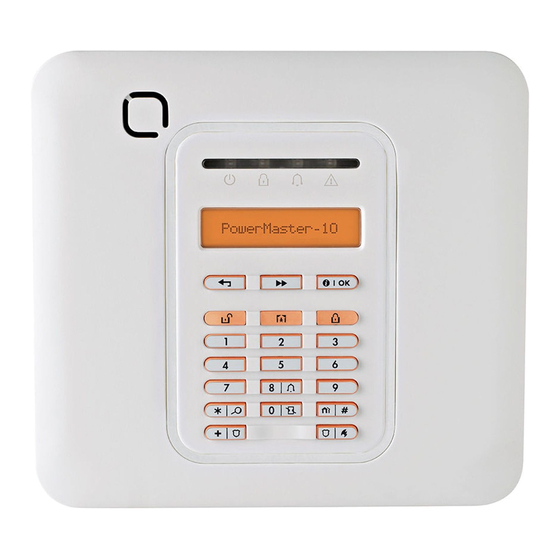
- Page 1 Installer Guide PowerMaster-10 Fully supervised wireless alarm control system...
-
Page 2: Table Of Contents
PowerMaster-10 Installer Guide TABLE OF CONTENTS 4.5.2 Adding a Wireless Device..... 16 1. INTRODUCTION ............4 4.5.3 Adding Wired Zones ......20 4.5.4 Deleting a Device........21 2. SPECIFICATIONS.............4 4.5.5 Modifying a Device ........ 22 2.1 Functional............4 4.5.6 Replacing a Device........ 23 4.5.7 Defining Defaults........ - Page 3 4.9.7 Enabling Latchkey Arming ....52 7.2 Dismounting the Control Panel ....72 4.10 User Interface Customization....53 7.3 Replacing the Backup Battery....72 4.10.1 Enabling Trouble Beeps...... 53 7.4 Fuse Replacement ........72 4.10.2 Enabling Piezo Beeps ......53 4.10.3 Enabling the Back Light ...... 54 7.5 Replacing/Relocating Detectors....
- Page 4 MESSAGE TO THE INSTALLER The PowerMaster-10 control panel is supplied with 3 instruction manuals: Installer Guide (this manual - for your exclusive use) User’s Guide (for your use during installation only - Must be handed over to the master user after testing the system) Accessories Guide (includes a full description of devices that are supported by the PowerMaster-10 system) Appendices A.1 and A.2 will help you prepare an installation plan.
-
Page 5: Introduction
1. INTRODUCTION The PowerMaster-10 is a user and installer-friendly, 29-zone fully-supervised wireless control system. The system is designed to function in an appealing way to the user and also offers features that make installers’ life easier than ever before: EASY TO MAINTAIN •... -
Page 6: Wireless
Data Retrieval Alarm memory, trouble, event log Real Time Clock (RTC) The control panel keeps and displays time and date. This feature is also used for the log file by providing the date and time of each event Compliance with U.S. USA: (FCC) CFR 47part 15 and part 68 Standards: Canada: RSS 210... -
Page 7: Physical Properties
Ring Detection The unit does not support ring detection without DC voltage present on the telephone lines. 2.5 Physical Properties Operating Temp. Range 14°F to 120°F (-10°C to 49°C) Storage Temp. Range -4°F to 140°F (-20°C to 60°C) Humidity 85% relative humidity, @ 30°C (86°F) Size 196 x 180 x 55 mm (7-5/8 x 7 x 2 in.) Weight... -
Page 8: Connecting Power To Panel
3.1.2 Connecting Power to Panel Connect the power cable and close the control panel as shown below. Electrical socket-outlet shall be installed near the equipment and shall be easily accessible. WARNING! DO NOT USE AN OUTLET CONTROLLED BY A WALL SWITCH. Note: This equipment should be installed in accordance with Chapter 2 of the National Fire Alarm Code, ANSI/NFPA 72, (National Fire Protection Association). -
Page 9: System Planning & Programming
A. SET B. LINE C. RJ-31X cord D. 8-position RJ-31X plug E. Gray F. Red G. Green H. Brown RJ-31X jack J. Line from street K. House phones This equipment is designed to be connected to the In the case that RJ31X is not available (consult your telephone network using RJ11 connector which telephone company or a qualified installer), the complies with Part 68 rules and requirements adopted... -
Page 10: Mounting The Unit
Gather up all transmitters and detectors used in the system and mark each one in accordance with your deployment plan. Program the system now, before mounting, as instructed in the programming section. 3.3 Mounting the Unit Required tool: Philips screwdriver #2. PowerMaster-10 mounting process is shown in Figure 3.3 - 3.4. -
Page 11: Extension Modules Installation
3.4 Extension Modules Installation 3.4.1 GSM Installation The internal GSM 350 module enables the PowerMaster-10 system to operate over a GSM/GPRS cellular network (for further details, see the GSM 350 PG2 Installation Instructions). The GSM modem auto detection feature enables automatic enrollment of the GSM modem into the PowerMaster-10 control panel memory. -
Page 12: Programming
4. PROGRAMMING 4.1 General Guidance We recommend programming the PowerMaster-10 on the work bench before actual installation. Operating power may be obtained from the backup battery or from the AC power supply. 4.2 Entering the Installer Menu The following procedure describes how to enter the Installer Menu. To Enter the Installer Menu Make sure the system is disarmed and then press the button... -
Page 13: Navigation
4.3 Navigation This mode allows you to customize the control panel and adapt its characteristics and behavior to the requirements of the particular user. To review the options within the control panel menus, repeatedly press the button, until the desired option is displayed, then press the button. -
Page 14: Setting The Master Installer Code
Enter the new 4-digit Installer Code (8888 or 9999) at the position of the INST. CODE blinking cursor and then press NEW INST. CODE * The default Installer Code is 9999. If your system uses MASTER CODE, you should proceed to setting the MASTER INSTALLER code in section 4.4.2 by pressing the button, or press the... -
Page 15: Setting User Codes
"*", "installer code", "#" b. Wait for 2 beeps "*", "1", "#" "*", "99", "#" Visonic uses Technistore anti code reset. Installers should check with their Monitoring Station for a code version (seed code) which needs to be entered. D-302756... -
Page 16: Configuring A Duress Code
To Configure Permissions for System Reset after an Alarm Event Repeat steps 1 to 4 of section 4.2 "Entering the Installer Menu". DEFINE PANEL 01:ENTRY DELAY 1 25:RESET OPTION Select between "user reset" (default), "engineer reset" and "anti user reset code reset". -
Page 17: Zones / Devices
4.5 Zones / Devices 4.5.1 General Guidance The ZONES / DEVICES mode enables the following functions: - Defining default parameters common for each devices family. - Adding new devices (enrolling) and defining their zones name, zone type and chime zone. Deleting devices. - Page 18 DEVICE ENROLLED K01:Keyfob Z01:Motion Sens ……….. S01:Siren The PowerMaster-10 display reads " " (or " DEVICE ENROLLED " if the device was enrolled manually by entering the ID number) accepted and the PowerMaster-10 display will then change to " K01:Keyfob / depending on the type of enrolled Z01:Motion Sens / S01:Siren device".
- Page 19 To understand the behavior of each zone, see section 4.5.2.3 Zone Types. 3.Home Delay Z01:SET CHIME Press to change chime settings or press the button to skip. Chime off…. Select between "Chime off" and "melody-chime". Note: In "melody chime" mode when a chime zone is triggered, chime melody is heard.
- Page 20 Emergency Zones: You can provide incapacitated, sick or elderly people with a miniature single-button transmitter to be carried on the neck like a pendant or to be worn on the wrist like a watch. In distress situations, they can press the button on their transmitter, causing the PowerMaster-10 to send an emergency call to the Monitoring Station or to private telephones designated by the installer.
-
Page 21: Adding Wired Zones
Child room Closet (UK: Conservatory) Den (UK: Playroom) Dining room Downstairs Emergency Fire Front door Garage Garage door Guest room Hall Kitchen Laundry room Living room Master bath Master bdrm Office (UK: Study) Upstairs Utility room Yard (UK: Garden) Custom 1 Custom 2 Custom 3 Custom 4... -
Page 22: Deleting A Device
ZONE WIRING 2.2k Ω 2.2k Ω A. ZONE B. TAMPER C. ALARM Note: Do not use mains cable other than that supplied by the manufacturer (3 m long). Figure 4.1 - Wiring 4.5.4 Deleting a Device C. To Delete a Device Repeat steps 1 to 3 in section 4.5.2 "Adding a Wireless Device". -
Page 23: Modifying A Device
(OFF) to delete MOTION SENSORS The device is deleted from the PowerMaster-10 system. When exiting "ZONES / DEVICES" menu the PowerMaster-10 system displays the number of devices that need to be updated, as follows: DEV UPDATING NNN. You can now press the button to delete the device of the same type, or press the button to delete a different device, or press the... -
Page 24: Replacing A Device
Z01: SET CHIME Press to change chime settings or press the button to skip. Chime off…. Select between "CHIME OFF" and "melody-chime". Note: In "melody chime" mode when a chime zone is triggered, chime melody is heard melody-chime You can now press the button to modify the next device of the same type, or press the button to configure the parameters of the... -
Page 25: Defining Defaults
Enroll the new device, or, enter the last 4 digits of the ID number of the ENROLL NOW or new device.* ENTR ID:100-xxxx The PowerMaster-10 display will read the result.** DEVICE ENROLLED Z01: Contact Sens ID No. 100-2332 If the device was previously enrolled in the system, the PowerMaster- 10 display reads "... -
Page 26: Siren Configuration
For reviewing parameter configurations refer to the PowerMaster-10 Accessories Guide in section "MODIFY DEVICE SETTINGS" of the desired device. At the end of the procedure you can press the button and perform the same procedure for a different device or you can press the button to take you to “... -
Page 27: Configuring The Period Of Strobe Light Activation
piezo siren ON Select between "piezo siren ON" and "piezo siren OFF". 24:PIEZO SIREN You can now press the button to program any other menu in " " or press the button to take you to " DEFINE PANEL <OK> ". -
Page 28: Event Reporting Configuration
disable on fail Select between "disable on fail" and "enable on fail". 27:SIREN ON LINE You can now press the button to program any other menu in " " or press the button to take you to " DEFINE PANEL <OK>... - Page 29 DIAL METHOD Here you prevent the GSM Service provider from disconnecting the GSM GSM KEEP ALIVE line if the user has not initiated any outgoing telephone calls during the last 28 days. disable Select between "disable" and "every 28 days". GSM KEEP ALIVE You can now press the button to revert to the "...
- Page 30 Here you determine whether the alarm system will report events to the SMS REPORT Monitoring Station via the SMS Channel. disable Select between "disable" and "enable". SMS REPORT GPRS APN Enter the name of the APN Access Point used for the internet settings for APN NAME the GPRS (up to 40 digits).
-
Page 31: Configuring Event Reporting To Monitoring Station
Here you determine whether the alarm system will report events to the FORCE HOME NTWK. Monitoring Station via the GSM Voice channel. disable Select between "disable" and "enable". FORCE HOME NTWK. Here you determine whether the control panel will stay continuously SESSION TIMEOUT connected via GPRS communication, or, temporarily connected to receive event reports only. - Page 32 Group Abbr. Events Reported Alarms alrm Fire, Burglary, Panic, Tamper Open/close Arming AWAY, Arming HOME, Disarming Alerts Alrt No-activity, Emergency, Latchkey Maintenance Low-battery AC failure "Alarm" group has the highest priority and "Alert" group has the lowest priority. The selectable options are as follows: Plan name Sent to center 1 Sent to center 2...
- Page 33 Here you define the 1st priority of method used to report events. 1st RPRT METHOD disable Select between "disable", "cellular", "broadband" and "PSTN". 1st RPRT METHOD Here you define the 2 priority method used to report events. If the 2nd RPRT METHOD method defined to report events in the 1st priority fails, the control panel will attempt to report using the method defined in the 2nd priority.
- Page 34 REPORT EVENTS Here you enter the number that will identify your specific alarm control RCVR 1 ACCOUNT# system to the 1 Monitoring Station. The number consists of 6 hexadecimal digits. 1st acc. #001234 Enter the first receiver account number. 1st RCVR ACC. NO. RCV 1 ACCOUNT# Here you enter the number that will identify your system to the 2 RCV 2 ACCOUNT#...
- Page 35 PSTN/GSM RCVR 2 Here you enter the IP address of the IP receiver that is located in the 1 IP RCVR 1 Monitoring Station. Enter the IP address of the first IP receiver (for further details see the 000.000.000.000 table at the end of this section). IP RCVR 1 Here you enter the IP address of the IP receiver that is located in the 2 IP RCVR 2...
- Page 36 Hex.Digit Keying Code Sequence Significance ⇒ <#> <0> Applicable only at the beginning of a number - the dialer waits 10 seconds or waits for dial tone, whichever comes first and then dials. ⇒ <#> <3> Applicable only at the beginning of a number - the dialer waits 5 seconds for dial tone and goes on hook if none is received.
- Page 37 Here you determine the number of times the communicator will dial the PSTN RPRT RETRY Monitoring Station’s number via PSTN. 4 attempts Select between "2 attempts", "4 attempts", "8 attempts", "12 attempts" and "16 attempts". PSTN RPRT RETRY Here you determine the number of times the communicator will try to GSM RPRT RETRY report via a cellular group (GPRS, GSM and SMS) to the Monitoring Station.
- Page 38 Here you determine the time interval between consecutive telephone line AUTO TEST CYCLE test messages sent to the Monitoring Station. The control panel performs this at regular intervals to verify proper communications. test OFF Select between "test OFF", "test every 1 d", "test every 2 d", "test every 5 d", "test every 7 d", "test every 14 d", "test every 30 d"...
- Page 39 broadband LINE FAIL REPORT You can now press the button to take you to the " " PSTN UP/DOWN menu (see Configuring Remote Programming Access Permissions), or press the button to take you to " ". <OK> TO EXIT 4.7.3.8 Configuring the Event Types to be Reported to the Monitoring Station Continue below from the previous section or repeat steps 1 to 4 of section 4.7.3.1 before continuing with the following instructions: REPORT EVENTS...
-
Page 40: Configuring Event Reporting To Users
disable Select between "disable", "rep. after 7d", " rep. after 14d ", " rep. after 30d", and "rep. after 90d". SYS INACT REPORT You can now press the button to take you to the " REPORT " menu (see section 4.7.2.1), or press the button to take EVENTS you to "... - Page 41 You can now press the button to take you to the " VOICE " menu, or press the button to take you to " REPORT <OK> TO ". EXIT C. To Configure Event Types to be Reported to User VOICE REPORT 1st private tel# Enter the first private telephone number (including area code, if required) 1st PRIVATE TEL.
- Page 42 3 attempts Select between "1 attempt", "2 attempts", "3 attempts" and "4 attempts". Attention! A maximum of 2 dialing attempts is permitted by the Australian Telecommunication Authority. Redial attempts Here you determine whether the system will use the single acknowledge Tel.
-
Page 43: Security System Configuration
2nd SMS tel# 3rd SMS tel# Enter the third SMS phone number (including area code, 16 digits max.) 3rd SMS TEL. NO. to which pre-selected event types will be reported. 3rd SMS tel# 4th SMS tel# Enter the fourht SMS phone number (including area code, 16 digits max.) 4th SMS TEL. -
Page 44: Configuring Swinger Stop
14:CROSS ZONING You can now press the button to program any other menu in " " or press the button to take you to " DEFINE PANEL <OK> ". TO EXIT 4.8.2 Configuring Swinger Stop Here you determine the number of times each zone is allowed to initiate an alarm within a single arming/disarming period (including tamper &... -
Page 45: Configuring Alarm Cancel Period
21:NOT ACTIVE no act disable Select between "no act disable", "3 h", "6 h", "12 h", "24 h", "48 h", and "72 h". 21:NOT ACTIVE You can now press the button to program any other menu in " " or press the button to take you to "... -
Page 46: Configuring Abort Time
To Configure the Power Failure Threshold Period Repeat steps 1 to 4 of section 4.2 "Entering the Installer Menu". DEFINE PANEL 01:ENTRY DELAY 1 34:AC FAIL REP 5 minutes Select between "5 minutes", "30 minutes", "60 minutes", and "180 minutes". 34:AC FAIL REP You can now press the button to program any other... -
Page 47: Configuring A Confirmed Alarm
4.8.7 Configuring a Confirmed Alarm Here you determine that if 2 successive alarms will occur during a specific period, the second alarm will be considered as a confirmed alarm for confirmed alarm reporting, (see par. 4.6.3.2 "Configuring the Event Types to be Reported"). -
Page 48: Configuring The Jamming Detection
You can now press the button to program any other menu in " " or press the button to take you to " DEFINE PANEL <OK> ". TO EXIT 4.8.9 Configuring the Jamming Detection Here you determine whether jamming (interfering transmissions, on the radio channel used by the system) will be detected and reported or not. -
Page 49: Configuring The Time Period By Which A Device Is Considered Missing
To Configure whether a missing device causes the system to become "NOT READY" Repeat steps 1 to 4 of section 4.2 "Entering the Installer Menu". DEFINE PANEL 01:ENTRY DELAY 1 16:NOT READY normal Select between "normal", and "in supervision". 16:NOT READY You can now press the button to program any other menu in "... -
Page 50: Arming/Disarming Options And Exit/Entry Delay
4.9 Arming/Disarming Options And Exit/Entry Delay 4.9.1 Configuring Exit Modes Here you determine exit delay mode options. Three types of exit delay modes are available: restart exit - Exit delay restarts when the door is reopened during exit delay. The restart occurs once only. Restarting the exit delay is helpful if the user re-enters immediately after going out to retrieve an item that he left behind. -
Page 51: Configuring Exit Delay Duration
entry dly1 30s Select between "entry dly1 00s", "entry dly1 15s", "entry dly1 30s", "entry dly1 45s", "entry dly1 60s", "entry dly1 3m" and "entry dly1 4m".** 09:EXIT MODE Press the button for " ". 02:ENTRY DELAY 2 ** In the " "... -
Page 52: Configuring Bypassing Zones
To Enable Quick Arm Repeat steps 1 to 4 of section 4.2 "Entering the Installer Menu". DEFINE PANEL 01:ENTRY DELAY 1 07:QUICK ARM quick arm OFF Select between "quick arm ON", and "quick arm OFF". 07:QUICK ARM You can now press the button to program any other menu in "... -
Page 53: Configuring Panic Alarm Activation
4.9.6 Configuring Panic Alarm Activation Here you determine whether the user will be allowed to initiate a panic alarm by simultaneous pressing of either the two panic buttons (on the keypad / wireless commander) or away + home (on a keyfob transmitter). Audible panic activates the siren and simultaneously transmits a message via telephone. -
Page 54: User Interface Customization
You can now press the button to program any other menu in " " or press the button to take you to " DEFINE PANEL <OK> ". TO EXIT 4.10 User Interface Customization 4.10.1 Enabling Trouble Beeps Under trouble conditions, the sounder emits a series of 3 short beeps once per minute. Here you determine whether this special beeping sequence will be active, inactive, or just inactive at night (the range of “night”... -
Page 55: Enabling The Back Light
enable beeps Select between "enable beeps", "off when home" and "disable beeps". 10:PIEZO BEEPS You can now press the button to program any other menu in " " or press the button to take you to " DEFINE PANEL <OK> ". -
Page 56: Configuring The Screen Saver Options
01:ENTRY DELAY 1 29:DISARM OPTION any time Select between "any time", "on entry wrless", "entry + away kp" and "on entry all". 29:DISARM OPTION You can now press the button to program any other menu in " " or press the button to take you to "... -
Page 57: Enabling The Memory Prompt
4.10.6 Enabling the Memory Prompt Here you determine whether the user will receive indication that an alarm has been activated. Available options are: enable (default) and disable. To Enable the Memory Prompt Repeat steps 1 to 4 of section 4.2 "Entering the Installer Menu". DEFINE PANEL 01:ENTRY DELAY 1 28:MEMORY PROMPT... -
Page 58: Define Custom Locations
4.11 DEFINE CUSTOM LOCATIONS This mode allows you to define up to 5 locations (in addition to the locations that can be defined in the ZONES / DEVICES mode - see par. 4.4). To Define Custom Locations Repeat steps 1 to 4 of section 4.2 "Entering the Installer Menu". DEFINE CUSTOM CUST. -
Page 59: Define
4.12.2 Define PGM For the PGM output, you can select disable, turn on, turn off or pulse active (turn on for predefined period, selected by PULSE TIME), as follows: ARM AWAY (upon AWAY arming). ARM HOME (upon HOME arming). DISARM (upon disarming). MEMORY (activated upon registration of an alarm in the memory, turned off upon memory clearing). - Page 60 PGM: BY ARM HOME PGM: BY DISARM disable Select between "disable", "turn ON", "turn OFF" and "pulse active". PGM: BY DISARM PGM: BY MEMORY disable Select between "disable", "turn ON", "turn OFF" and "pulse active". PGM: BY MEMORY PGM: BY DELAY disable Select between "disable", "turn ON", "turn OFF"...
- Page 61 Enter the number of the first zone that you designate for activating this a – zone Z:00 output. disable Select between "disable", "turn ON", "turn OFF", "pulse active" and "toggle". a - zone b - zone Enter the number of the second zone that you designate for activating b –...
- Page 62 B. To Configure PGM Lighting Devices in Alarm Conditions and To Set Daytime Limits of Lighting Devices Repeat steps 1 to 4 of section 4.2 "Entering the Installer Menu". DEFINE OUTPUTS DEFINE PGM PGM: GENERAL DEF FLASH ON ALARM no flash Select between "no flash"...
-
Page 63: Configuring Remote Programming Access Permissions
4.13 Configuring Remote Programming Access Permissions Repeat steps 1 to 4 of section 4.2 "Entering the Installer Menu". DEFINE COMM. 1:PSTN/GSM 3:C.S. REPORTING REPORT EVENTS PSTN UP / DOWN Here you give or deny permission to access the system and exercise Remote access control from a remote telephone. - Page 64 any time Select between "any time" and "when system OFF". Upload option Here you enter the telephone number (up to 16 digits) of the UL/DL server. Up/Download tel# Note: Only for use of control panels monitored by compatible Monitoring Stations. Leave empty if not used. Enter the upload/download software telephone number.
-
Page 65: Diagnostic Test
Enter the second IP receiver telephone number. 2nd caller ID# GPRS UP / DOWN You can now press the button to take you to the " RPRT CNFRM " menu (see section 4.7.3.8), or press the button to take ALARM you to "... -
Page 66: Testing One Device
Note: "Zxx" indicates the type of device and device number that is being tested. "NNN" indicates the number of devices that have not yet been tested. At this stage if any key is pressed the PowerMaster-10 display will read " "... -
Page 67: Displaying Signal Strength Indication Of All Devices
Z01 24Hr: EARLY After testing the PowerMaster-10 display will then automatically change to read the average level for the last 24 hours (for stationary devices) or the number of activations that the control panel has received (for keyfobs). The signal strength indications are as follows: " ";... -
Page 68: Displaying Signal Strength Indication Of Rf Devices
5.1.4 Displaying Signal Strength Indication of RF Devices Repeat steps 1 to 4 of section 4.2 "Entering the Installer Menu". DIAGNOSTICS WL DEVICES TEST ALL DEVICES SHOW RF PROBLEMS The PowerMaster-10 display switches between the average signal Z01: 24hr: GOOD strength indication for the last 24 hours and the current signal strength indications of the first device type.∗... -
Page 69: Lan Connection Test
PLEASE WAIT… UNIT IS OK See the table below for a complete list of possible GSM/GPRS messages. ∗ If there are no wireless devices enrolled in the PowerMaster-10 system, the PowerMaster-10 display reads " ". NO DEVICES ** When the button is pressed the test result takes up to 4 min. -
Page 70: Lan Reset Option
See the table below for a complete list of possible LAN messages. ∗ If there are no wireless devices enrolled in the PowerMaster-10 system, the PowerMaster-10 display reads " ". NO DEVICES ** When the button is pressed the test result takes up to 4 min. before it is displayed, depending on the severity of the failure. -
Page 71: Calling Upload/Download Server
To reset the PowerLink Broadband Module REBOOT To reset all LAN setting definitions (does not reset Monitoring Station IP definitions) FACTORY DEFIN. FACTORY DEFIN. ∗ If there are no wireless devices enrolled in the PowerMaster-10 system, the PowerMaster-10 display reads " ". -
Page 72: Maintenance
Pressing the buttons at any stage in the procedure will take you to “ ”. <OK> TO EXIT 7. MAINTENANCE 7.1 Handling System Troubles Fault What it means Solution 1-WAY The control panel cannot configure or i) Make sure the device is physically control the device. -
Page 73: Dismounting The Control Panel
Fault What it means Solution SIREN AC There is no power to the siren Make sure that the AC power supply is FAILURE connected properly AC FAILURE There is no power to gas sensor Make sure that the AC power supply is connected properly GSM NET FAIL The GSM communicator is not able to... -
Page 74: Replacing/Relocating Detectors
7.5 Replacing/Relocating Detectors Whenever maintenance work involves replacement or re-location of detectors, always perform a full diagnostic test according to section 5. Remember! A "poor" signal is not acceptable, as stated at the end of the introduction to the test procedure. 7.6 Restoring Factory Defaults If you want to reset the PowerMaster-10 parameters to the factory default parameters, you should enter the installer menu and perform the "FACTORY DEFLT"... -
Page 75: Reading The Event Log
8 READING THE EVENT LOG Events are stored in the event log. You can access this log and review the events, one by one. If the event log fills up completely, the oldest event is deleted upon registration of each new event. The date and time of occurrence are memorized for each event. -
Page 76: Appendix A. Detector Deployment & Transmitter Assignments
APPENDIX A. Detector Deployment & Transmitter Assignments A1. Detector Deployment Plan Zone Zone Type Sensor Location or Transmitter Assignment Chime (in non-alarm or emergency zones) (Yes / No) 29 (*) 30 (*) Zone Types: 1 = Interior follower 2 = Perimeter 3 = Perimeter follower 4 = Delay 1 5 = Delay 2... -
Page 77: A2. Keyfob Transmitter List
A2. Keyfob Transmitter List Transmitter Data AUX button Assignments Type Holder Skip exit delay or Arming “instant” Indicate the desired function (if any) Skip exit delay Arming “instant” A3. Emergency Transmitter List Tx # Transmitter Type Enrolled to Zone Name of holder A4. -
Page 78: Appendix B. Event Codes
APPENDIX B. Event Codes B1. Contact ID Event Codes Code Definition Code Definition Emergency Telco fault Fire Fire detector trouble Panic Loss of supervision RF Duress Sensor tamper Silent RF low battery Audible Fire detector clean me Perimeter O/C by user Interior Auto arm Entry/Exit... - Page 79 Alarms Zone # 1 2 3 4 5 6 7 8 9 10 11 12 13 14 15 16 17 18 19 20 21 22 23 24 25 26 27 28 29 digit 4 4 4 4 4 4 4 4 4 4 4 4 4 4 4 5 5 5 5 5 5 5 5 5 5 5 5 5 5 1 2 3 4 5 6 7 8 9 A B C D E F 1 2 3 4 5 6 7 8 9 A B C D E digit Restorals...
-
Page 80: B4. Understanding The Scancom Reporting Protocol Data Format
Trouble Event Fuse Fuse Jamming Jamming CPU Low Fail Restore Restore Failure Restore Battery Tamper Battery Restore digit digit Event CP Tamper No Active COMM. & Enter Test Exit Test Auto Test Restore LINE Restore digit digit B4. Understanding the Scancom Reporting Protocol Data Format The SCANCOM data format consists of 13 decimal digits divided into 4 groups, from left to right, as shown at the right side. -
Page 81: Appendix C. Glossary
APPENDIX C. Glossary Control Panel: The control panel is a cabinet that This list of terms is arranged in alphabetical order. incorporates electronic circuitry Any term indicated by cursive (italic) letters within microprocessor that control the alarm system. It the explanatory text can be looked up separately. collects information from various sensors, processes Abort Period: When an alarm is initiated, the it and responds in various ways. - Page 82 Restore: When a detector reverts from the state of To disarm the system without causing an alarm, use alarm to the normal standby state, it is said to have your control keypad (which is normally accessible without disturbing a perimeter zone) or use a keyfob been “restored”.
-
Page 83: Appendix D. Default And Programmed Zone Definitions
APPENDIX D. DEFAULT AND PROGRAMMED ZONE DEFINITIONS Zone Zone Type Location Chime (melody Default Programmed Default Programmed Location or Off) (*) Delay 1 Front Door Delay 1 Garage Delay 2 Garage Door Perimeter Back Door Perimeter Child Room Interior Office Interior Dining Room Perimeter... - Page 84 Industry Canada Declaration This product meets the applicable Industry Canada technical specifications/Le présent materiel est conforme aux specifications techniques appliables d’Industrie Canada. The Ringer Equivalence Number is an indication of the maximum number of devices allowed to be connected to a telephone interface.
- Page 85 WARRANTY Visonic Limited (the “Manufacturer") warrants this product only (the "Product") to the original However, if the Manufacturer is held liable, whether directly or indirectly, for any loss or purchaser only (the “Purchaser”) against defective workmanship and materials under normal...
- Page 86 Fully supervised wireless alarm control system Fully supervised wireless larm control system Fully supervised wireless alarm control system Fully supervised wireless alarm control system Fully supervised wireless alarm control system Fully upervised wireless alarm control system Fully supervised wireless alarm control www.visonic.com...
Need help?
Do you have a question about the POWERMASTER-10 - INSTALLER GUIDE and is the answer not in the manual?
Questions and answers