Visonic PowerMaster-10 G2 User Manual
Fully supervised wireless alarm control system
Hide thumbs
Also See for PowerMaster-10 G2:
- Quick user manual (96 pages) ,
- Installer's manual (82 pages) ,
- User manual (62 pages)

Related Manuals for Visonic PowerMaster-10 G2


Summary of Contents for Visonic PowerMaster-10 G2
- Page 1 USER GUIDE PowerMaster-10 G2 Fully supervised wireless alarm control system www.visonic.com...
-
Page 2: Table Of Contents
Speech & Sound Cont. Push-buttons ..14 Overview ............3 Voice ON/OFF ..........14 System Features ..........3 Message Exchange ........14 PowerMaster-10 G2 Panel Indicator and Message Playback ........15 Controls ............4 4. Electrical Appliance Control ......16 LED Indicators ..........4 Control Options and Pushbuttons .... - Page 3 Event notifications by Telephone ....49 APPENDIX B. PARTITIONING ......62 Event notifications by SMS ......50 B1. Selecting a Partition ......62 Remote Control by Telephone ..... 50 B2. Arming / Disarming the System ..... 62 Remote Control by SMS ....... 52 B3.
-
Page 4: Introduction
• Master / User Settings: Two user levels allow different access types (see Chapter 6. Menus and Functions, section B.4 Programming User Codes). • 30 detector zones (PowerMaster-10 G2) / 64 detector zones (PowerMaster-30 G2): Each detector zone is identified by zone number and name (location). -
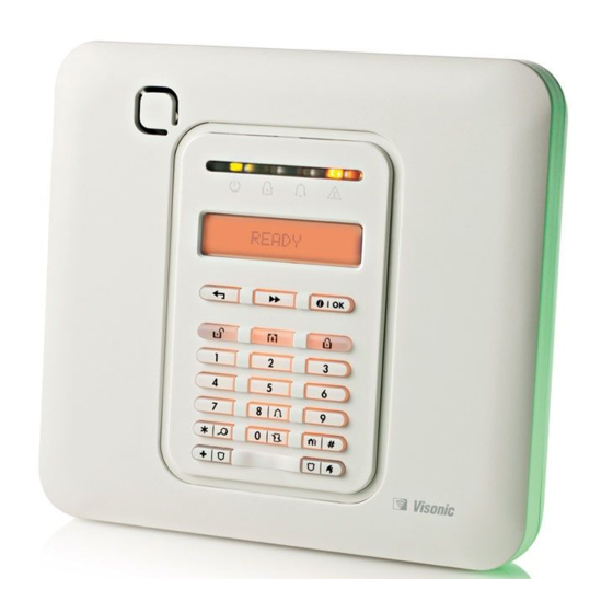
Page 5: Powermaster-10 G2 Panel Indicator And Controls
30 days. Wireless sirens can still provide 2 siren alarms before the siren becomes totally inactive. Note: When the ‘Low Battery’ message is received, the battery should be replaced within 7 days. PowerMaster-10 G2 Panel Indicator and Controls Figure 1a. PowerMaster-10 G2 Controls and Indicators LED Indicators Indication Function Power (Green): Indicates that your system is properly connected to the power outlet. -
Page 6: Control Keys
INTRODUCTION Control Keys Indication Function NEXT: Advance from item to item within a given menu. BACK: Move one step back within a given menu. OK: Review status messages one by one and also select a displayed option. Arming Keys Indication Function AWAY: Arming when nobody is at home HOME: Arming when people remain at home. -
Page 7: Control Keys
INTRODUCTION Indication Function Arm (Red): Lights when the system is in the armed state. Chime (Green): Chime zones will chime when disturbed (see Chapter 2). Trouble (Orange): Lights when the system is in a state of trouble (see Chapter 5). Control Keys Indication Function... -
Page 8: Built-In Alarm Sounder
INTRODUCTION Built-in Alarm Sounder The PowerMaster panel has a high power siren built-in that sounds in case of alarm to deter intruders and to summon help. The maximum operating time of the siren is configured by the installer according to local regulations. Continuously ON when initiated by a burglar zone or a 24-hour zone, and when a user initiates a “panic alarm”. -
Page 9: Screen Saver Mode
(see Chapter 6, B.4 Programming User Codes). Moreover, you can obtain up to 8 (PowerMaster-10 G2) / 32 (PowerMaster-30 G2) multi-function portable keyfob transmitters that will allow you and the other users to easily arm, disarm and control the system without accessing the panel, including from outside the premises (see Chapters 2 and 6, B.7 Add / Delete Keyfob... -
Page 10: Operating The Powermaster System
For more information regarding terms used in this chapter, refer to APPENDIX C. GLOSSARY. Note: This manual displays PowerMaster-10 G2 panel buttons only, even when instructions refer to both panels. When an instruction refers to PowerMaster-30 G2 only, the PowerMaster-30 G2 panel buttons are displayed. -
Page 11: Disarming Under Duress
OPERATING THE POWERMASTER SYSTEM After disarming, different displays may appear indicating that the system is in a state of alarm MEMORY. The MEMORY message will disappear only upon rearming the system. To disarm the system, proceed as shown: PRESS RESULTING DISPLAY PRESENT TAG OR ENTER CODE _ _ _ _... -
Page 12: Arming Away Or Home 'Instant
OPERATING THE POWERMASTER SYSTEM Arming AWAY or HOME ‘Instant’ Pressing during the exit delay will arm the system in the "Instant' mode, i.e. without an entry delay. Therefore, any detection in any zone will trigger an immediate alarm. To arm AWAY-INSTANT, proceed as follows. PRESS RESULTING DISPLAY PRESENT TAG OR... -
Page 13: Arming In The Latchkey Mode
“latchkey user”. Latchkey users are holders of user codes or users of keyfob transmitters 5 through 8 (PowerMaster-10 G2) / 23- 32 (PowerMaster-30 G2). The latchkey message is considered an alert and not an alarm, and is therefore sent to the private telephones programmed by the user as targets for alert messages. -
Page 14: Initiating Fire Alarm Or Emergency Alarm
OPERATING THE POWERMASTER SYSTEM Initiating Fire Alarm or Emergency Alarm You can generate a fire alarm or a silent emergency alarm in disarmed & armed states, as follows: PRESS RESULTING DISPLAY FIRE ALARM EMERGENCY for 2 seconds Then, if or when the system is in the disarmed state: READY HH:MM (alternating) -
Page 15: Speech And Sound Control
SPEECH AND SOUND CONTROL 3. Speech and Sound Control Speech & Sound Cont. Push-buttons The sound and speech-related functions offered by the control panel are controlled with the keypad, as detailed in the following list. When partitioning is enabled: Sound and speech-related features only apply to the partition(s) where the control panel is present. An activity performed via the control panel from another partition will be displayed and the LED will light. -
Page 16: Message Playback
SPEECH AND SOUND CONTROL Once the last of the boxes disappears, RECORDING ENDED will be displayed. When you release the button, the display will revert to the normal status-displaying mode, but will also indicate that a message is waiting. For example: READY HH:MM (alternating) -
Page 17: Electrical Appliance Control
ELECTRICAL APPLIANCE CONTROL 4. Electrical Appliance Control Control Options and Pushbuttons The system allows manual or automatic remote control of a device connected to the PGM output. The user defines the ON and OFF times via the Scheduler (see Chapter 6 - B.14 Programming the Scheduler). The installer determines which zone sensors will switch the remote controlled appliances on and off. -
Page 18: Reviewing Troubles And Alarm Memory
REVIEWING TROUBLES AND ALARM MEMORY 5. Reviewing Troubles and Alarm memory Alarm & Tamper Memory Indication The PowerMaster retains in its memory alarm and “tamper” events that occurred during the last arming period. Note: Alarm events are memorized only after the “abort period” (see Appendix C). This means that if you disarm the system immediately - before the abort period expires - there will be no memory indication A. -
Page 19: General Indications
REVIEWING TROUBLES AND ALARM MEMORY B. Displaying Trouble Information All trouble messages need to be reviewed and corrected as described below: EXAMPLE: The kitchen device - zone No. 9 - has reported a low battery – the living room device zone No. 15 - has been inactive, and an attempt to communicate a message to your telephone has failed. -
Page 20: Correcting Trouble Situations
REVIEWING TROUBLES AND ALARM MEMORY Correcting Trouble Situations The trouble indications (illuminated TROUBLE indicator and flashing TRBL message) are cleared once you eliminate the cause of trouble. The table below describes the system faults and respective corrective actions. If you do not know how to correct a trouble situation, report it to your installer and seek his advice. Fault What it means 1-WAY... -
Page 21: Menus And Functions
– see table at end of this section. Note: This manual displays PowerMaster-10 G2 control panel buttons only, even when instructions refer to both control panels. When an instruction refers to PowerMaster-30 G2 only, the PowerMaster-30 G2 control panel buttons are displayed. - Page 22 MENUS AND FUNCTIONS C. User Settings Options Menu Click until the display reads the desired setting option and then press Use to set the Zone Bypass Scheme i.e. to bypass (exclude) faulty or unsecured SET ZONE BYPASS ("disturbed") zones, or to clear a bypassed zone (unbypass). For further details and programming procedure see section B.1.
-
Page 23: Returning To The Previous Step Or Exiting The User Settings Menu
MENUS AND FUNCTIONS A.2 Returning to the Previous Step or Exiting the USER SETTINGS Menu During the setting process it is frequently necessary to return to the previous setting step or option (i.e. "to go one level up") or to exit the User Settings menu. A. - Page 24 MENUS AND FUNCTIONS 1. Zones will be bypassed throughout one disarm-arm period only. Disarming the system after arming will suspend the entire bypassing scheme but you can recall and reuse it as described in section B.3. 2. Fire zones cannot be bypassed. 3.
-
Page 25: Reviewing The Zone Bypass Scheme
MENUS AND FUNCTIONS B.2 Reviewing the Zone Bypass Scheme ♦ Here you can quickly review the Bypass Scheme i.e. the zones that are set to be bypassed during the next arming session. REVIEW BYPASS Enter the [USER SETTINGS] menu and select the [REVIEW BYPASS] option and press BYPASS LIST The display reads [BYPASS LIST]... -
Page 26: Programming User Codes
Each user out of the 8 (PowerMaster-10 G2) / 48 (PowerMaster-30 G2) system users can be authorized by the Master User to arm and disarm any combination of partitions including all 3 partitions. - Page 27 For detailed instructions on how to select the setting options – refer to sections A.1 and A.2. The display shows the 1 User Code (Master User) in the list of 8 User Codes (in PowerMaster-10 G2 system) / 48 User Codes (in PowerMaster-30 G2). If you have not yet changed the default code 1111, we recommend that you change it now.
-
Page 28: Programming The Duress Code
B.6 Add / Delete Proximity Tags A proximity tag may be assigned to each of the PowerMaster-10 G2 user codes 1-8 / PowerMaster-30 G2 user codes 1-32 that can be used instead of the user codes to perform a variety of functions, for example, arming, disarming, reading the event log, etc. - Page 29 MENUS AND FUNCTIONS the display reads [DEVICE ENROLLED] for a short duration and then ☺ Go to step 5 changes to read the tag's details. The display shows the allocated tag serial No (user No.), which is always the T01:Tag (Prox) first free number, for example: [T01:Tag (Prox)].
-
Page 30: Add / Delete Keyfob Transmitters
Partition Option (For information about Partition option - see Appendix B) If the Partition option is enabled in the control panel, each of the 8 keyfobs (PowerMaster-10 G2) / 32 keyfobs (PowerMaster-30 G2) can be authorized by the Master User to arm and disarm any combination, or all 3 partitions, irrespective of the authorization of its corresponding user code. - Page 31 MENUS AND FUNCTIONS B: ENROLLMENT BY DEVICE ID: Enter the 7-digit number that appears on ID No. 300-5786 the keyfob sticker and then press to confirm. To complete the enrollment procedure, see Note 9 in the Additional Information table below. ID ACCEPTED ☺...
- Page 32 LED may blink for several seconds more while trying to establish communication. During this period of time the keyfob keys are disabled. The display shows the first enrolled Keyfob (Keyfob No.1) of the 8 keyfobs (PowerMaster-10 G2 / 32 keyfobs (PowerMaster-30 G2).
-
Page 33: Setting The Time & Time Format
MENUS AND FUNCTIONS B.8 Setting the Time & Time Format ♦ Here you can program or adjust the built-in-clock to show the correct time in the desired time format. ♦ You can select between a 24 hour and a 12 hour (AM/PM) time format. Carefully read the section titled "Additional Information"... -
Page 34: Setting The Date & Date Format
MENUS AND FUNCTIONS B.9 Setting the Date & Date Format ♦ Here you can program or adjust the built-in-calendar to show the correct date in the desired date format. ♦ You can select between a "mm/dd/yyyy" and a "dd/mm/yyyy" date format. Carefully read the section titled "Additional Information"... -
Page 35: Enabling / Disabling Auto-Arming
MENUS AND FUNCTIONS B.10 Enabling / Disabling Auto-Arming The PowerMaster system can be programmed to automatically arm itself on a daily basis at a predetermined time. This feature is useful especially in commercial applications, such as in stores, to ensure that the system is always armed and without having to assign security codes to employees. -
Page 36: Programming Private Phone, Email, Mms And Sms Reporting
MENUS AND FUNCTIONS B.12 Programming Private Phone, Email, MMS and SMS Reporting The PowerMaster system can be programmed to send various event notification messages such as alarm, arming or trouble events, to 4 private telephone subscribers by audible signal and, if a GSM option is installed, also to 4 SMS telephone numbers. - Page 37 MENUS AND FUNCTIONS B. To Program a Private Phone Click the button until the display reads the Telephone No. REPORTED EVENTS you wish to program or edit, for example, "2nd private tel#", and press 2nd private tel# To program or edit the phone number, at the blinking cursor position enter the 032759333 6, 7 phone number, for example, “8032759333”, using the numerical keypad.
- Page 38 MENUS AND FUNCTIONS E. To Program the Acknowledge Method Click the button until the display reads [Tel. acknowledge] Voice<- ->private and press to confirm. Tel. acknowledge The display shows the currently selected option. by single ack Click the button until the display reads the desired acknowledge method, for example, "by all ack".
- Page 39 When the display reads [Address], press Address To program or edit the email, at the blinking cursor position enter the Email, info@visonic.com 6, 7 for example, “info@visonic.com”, using the alphanumerical keypad. When done, press to confirm. A "Happy Tune" ☺...
- Page 40 MENUS AND FUNCTIONS MMS/SMS BY SERVER A. To Program Events to be Reported by SMS via the server Enter the [USER SETTINGS] menu, select the [PRIVATE REPORT] option PRIVATE REPORT and press VOICE REPORT When the display reads [VOICE REPORTS] press repeatedly until the display reads [SMS/MMS BY SRVR].
- Page 41 ". Using the buttons you can now select the events you wish to be reported to private telephones numbers according to the options provided in the tables below: PowerMaster-10 G2 Event Group Option Events to be reported alarms+alerts Alarm and alert messages...
- Page 42 " – an acknowledge signal from only a single telephone will stop the reporting process. " by all ack " – an acknowledge signal from all telephones is required to stop the reporting process. If the control panel is PowerMaster-10 G2 or PowerMaster-30 G2 without Voice option, the display reads Redial attempts " ".
-
Page 43: Enabling / Disabling The Squawk Option
MENUS AND FUNCTIONS disable report The display shows the currently selected option (indicated by a symbol), for example, " ". Using the buttons you can now select the events you wish to be reported to MMS telephones numbers according to the options provided in the tables below: Event Group Option Events to be reported alarms+alrt... - Page 44 MENUS AND FUNCTIONS A. To Set the Scheduler Enter the [USER SETTINGS] menu, select the [SCHEDULER] option and SCHEDULER press When the display reads [PGM], press B. To Set the Day The 1 day of the scheduler is displayed. Sunday Click the button until the display reads the day you wish to schedule or "Daily", for example, "Tuesday".
- Page 45 MENUS AND FUNCTIONS Additional Information (section B.14) For detailed instructions on how to select the Setting Options – refer to sections A.1 and A.2. To activate the selected device on every day of the week at the same time(s), use the "Daily" option. Otherwise, use the buttons to select the specific day (Sunday, Monday, Tuesday…etc) you wish to activate the PGM output.
-
Page 46: Volume Control
MENUS AND FUNCTIONS B.15 Volume Control The system allows you to adjust the volume level of the various system beeps, chime signal and voice prompts, and to enable or disable status dependent, pre-recorded verbal messages (Voice option) that are heard over the built-in loudspeaker. - Page 47 MENUS AND FUNCTIONS C. To Adjust the Volume Level of the Exit Entry Beeps Click the button until the display reads [Exit Entry beeps], and press Exit/Entry beeps The display shows the currently selected option. Click the button until the display reads the desired volume level for the Exit/Entry beeps, for example, [MAX].
- Page 48 MENUS AND FUNCTIONS F. To Adjust the Volume Level of the Voice Announcements Click the button until the display reads [Voice volume], and press Voice volume The display shows the currently selected option. Click the button until the display reads the desired volume level for the voice announcements, for example, [MAX].
-
Page 49: Serial Number
Enter the [USER SETTINGS] menu, select the [ SERIAL NUMBER option and press Displays the control panel serial number. 090703000 Displays the PowerMaster-10 G2 panel software version. JS702271 I18.040 Displays the PowerMaster-30 G2 panel software version. JS702275 I18.040 Displays the control panel keypad software version. -
Page 50: Event Reporting And Control By Telephone And Sms
* PowerMaster-30 G2 only Note: For UL installations, SMS is a supplementary feature. PowerMaster-10 G2 control panels In case of alarm the following voice signal will be sent to private telephones upon event reporting: (- - - - - - FIRE: ON - ON - ON - pause.. -
Page 51: Event Notifications By Sms
EVENT REPORTING & CONTROL BY TELEPHONE AND SMS Event notifications by SMS Note: This feature is not to be not to be enabled in UL Listed product. The PowerMaster system when equipped with a GSM unit can be programmed to send SMS event notification messages to 4 pre-selected telephone numbers - see Chapter –... - Page 52 EVENT REPORTING & CONTROL BY TELEPHONE AND SMS Command Single Partition Keying All Partitions Keying Sequence Sequence Review status of specific partition [ ] [0] [partition] [9] [#] 1, 2 (Voice version only) [ #] Activating PGM output [ ] [5] [0] [0] [1] [#] [ ] [5] [device No.] [1] [ #]...
-
Page 53: Remote Control By Sms
EVENT REPORTING & CONTROL BY TELEPHONE AND SMS Remote Control by SMS Note: This feature is not to be not to be enabled in UL Listed product. PowerMaster system with GSM unit can respond to SMS commands from any cellular telephone (a detailed SMS message sending process is described in the cellular telephone user’s guide). -
Page 54: Special Applications And Functions
SPECIAL APPLICATIONS AND FUNCTIONS 8. Special Applications and Functions Looking after People Left at Home In addition to acting as an alarm system, the PowerMaster can also be used to monitor the movement of people at home when the system is in the disarmed state (or even when armed “HOME” with perimeter protection only), and report lack of motion in interior zones if there is no detection of motion within predetermined time limits. -
Page 55: Testing The System
TESTING THE SYSTEM 9. Testing the System Periodic Test The components of your security system are designed to be maintenance-free as much as possible. Nevertheless, it is mandatory to test the system at least once a week and after an alarm event to verify that all system sirens, detectors, keyfobs, keypads and other peripherals function properly. - Page 56 TESTING THE SYSTEM between the temperature, the sensor number and the sensor location. Repeatedly click the button to review the temperature of each zone Z01:Temp. Sensor (by Temperature Sensor). Guest room When the temperature of all zones has been reviewed, the display reads DEVICE TESTS END [DEVICE TESTS END].
-
Page 57: Periodic Test Per Partition
TESTING THE SYSTEM Periodic Test per Partition In addition to the regular Periodic Test, you can also test zones for enrolled sensors (excluding temperature sensors and sirens) that are assigned to a selected partition. A. To Conduct the Periodic Test per Partition P1:R P2:N P3:- Make sure the selected partition is disarmed and the other partitions are not in exit or entry delay and then press the partition (... -
Page 58: Maintenance
AC power and this trouble state continues for more than a few hours, the battery may need to be replaced. An original Visonic battery must be used of which there are a number of types. For assistance in battery replacement, contact Technical Support. -
Page 59: Exiting The Event Log
MAINTENANCE READY 00:00 ENTER CODE:_ When the PowerMaster display reads [ENTER CODE: _], enter the current CODE master user code. LIST OF EVENTS The "Happy Tune" will sound and the PowerMaster display will read [LIST OF EVENTS]. (see Important Note!) Click the button. -
Page 60: Appendix A. Functions Of Controlling Devices
APPENDICES APPENDIX A. FUNCTIONS OF CONTROLLING DEVICES A1. KP-160 PG2 Arming and Disarming the System Step Operation User Actions Keyboard & Panel Response Select a PARTITION Any combination of The selected key blinks. (if Partition is enabled) Arm AWAY The selected key and the "Present Prox Tag"... -
Page 61: A2. Kp-140/141 Pg2
APPENDICES A2. KP-140/141 PG2 Arming and Disarming the System Step Basic Arming User Actions Keypad & Panel Response Select a PARTITION The selected button lights. (Partition enabled) The selected button starts blinking Arm AWAY and prompts you to enter your "User Code"... -
Page 62: A3. Kf-234 Pg2
APPENDICES A3. KF-234 PG2 Keyfob Functionality Step Functions User Actions Response Arm AWAY When executing a command, the keyfob's LED blinks red once to indicate transmission of the command to Arm HOME the control panel. If the operation is successfully completed, the green LED lights momentarily and a Disarm (OFF) "happy tune"... -
Page 63: Appendix B. Partitioning
APPENDICES APPENDIX B. PARTITIONING The control panel includes an optional partition feature. Partitioning is available only if your installer has enabled the feature. Once partitioning is enabled Partitioning menus are added to the system which can be viewed on the control panel's LCD display. Partitioning allows you to divide the system into three independently controllable areas with different users assigned to each partition whereby each user can arm the partition to which they are assigned. -
Page 64: B4. Siren
APPENDICES B4. Siren A partition is alarmed when receiving an event from an alarmed device assigned to that partition. Alarmed devices do not affect partitions to which they are not assigned. A siren is common to all partitions; therefore, an alarm from one or more partitions will activate the siren. - Page 65 APPENDICES Table A1 – Common Area Definitions Common area zone types Definition • Acts as defined only after the last assigned partition is armed AWAY or Perimeter HOME. • In case that one of the partitions is disarmed, an alarm initiated from this zone is ignored for all assigned partitions.
-
Page 66: Appendix C. Glossary
APPENDICES APPENDIX C. GLOSSARY This list of terms is arranged in alphabetical order. Abort Period: When an alarm is initiated, the internal built-in sounder is activated first for a limited period of time which is the abort period set by the installer. If you cause an alarm accidentally, you can disarm the system within the abort period before the real sirens start and before the alarm is reported to the remote responders. - Page 67 APPENDICES HOME: This type of arming is used when people are present within the protected site. A classic example is night-time at home, when the family is about to retire to bed. With HOME arming, perimeter zones are protected but interior zones are not. Consequently, motion within interior zones will be ignored by the control panel, but disturbance of a perimeter zone will cause an alarm.
-
Page 68: Appendix D. Home Fire Escape Planning
APPENDICES APPENDIX D. HOME FIRE ESCAPE PLANNING Fire can spread rapidly through your home, leaving you a short time to escape safely. Your ability to get out depends on advance warning from smoke detectors and advance planning - a home fire escape plan that everyone in your family is familiar with and has practiced. -
Page 69: Appendix E. Specifications
APPENDICES APPENDIX E. SPECIFICATIONS E1. Functional PowerMaster-10 G2 PowerMaster-30 G2 Zones Number 30 wireless zones (including 1 hard-wired Up to 64 wireless zones, (including 2 hard- input). wired inputs). Hard-wired Zone 2.2 kΩ E.O.L. resistance (max. resistance of 2.2 kΩ E.O.L. resistance (max. resistance of wires 220 Ω). -
Page 70: E2. Wireless
APPENDICES PowerMaster-10 G2 PowerMaster-30 G2 Real Time Clock The control panel keeps and displays time and The control panel keeps and displays time and (RTC) date. This feature is also used for the log file by date. This feature is also used for the log file by... -
Page 71: E4. Communication
Local Computer Report 2 Monitoring Stations, 4 private telephones 2 Monitoring Stations, 4 private telephones Destinations Reporting Format SIA, Contact ID, Scancom, SIA IP, Visonic SIA, Contact ID, Scancom, SIA IP, Visonic Options PowerNet. PowerNet. Note: For UL Listed product, the... -
Page 72: E5. Physical Properties
The unit does not support ring detection without DC voltage present on the telephone lines. DC voltage present on the telephone lines E5. Physical Properties PowerMaster-10 G2 PowerMaster-30 G2 Operating Temp. 14° F to 120°F (-10° C to 49° C) 14°... -
Page 73: Appendix F. Compliance With Standards
If trouble is experienced with the “PowerMaster-10/30 G2” for repair or warranty information please contact Visonic Inc USA., 65 West Dudley Town Road, Bloomfield, CT 06002, phone number: 8 602 430 833, URL: www.visonic.com. If the equipment is causing harm to the telephone network, the telephone company may request to disconnect the equipment until the problem is resolved. - Page 74 USER GUIDE PowerMaster-30 G2 Fully supervised wireless alarm control system www.visonic.com...
Need help?
Do you have a question about the PowerMaster-10 G2 and is the answer not in the manual?
Questions and answers