Visonic PowerMaster-10 G2 User Manual
Fully supervised wireless alarm control system
Hide thumbs
Also See for PowerMaster-10 G2:
- Quick user manual (96 pages) ,
- Installer's manual (82 pages) ,
- User manual (74 pages)

Related Manuals for Visonic PowerMaster-10 G2


Summary of Contents for Visonic PowerMaster-10 G2
- Page 1 USER GUIDE PowerMaster-10 G2 Fully supervised wireless alarm control system www.visonic.com...
-
Page 2: Table Of Contents
3. Speech and Sound Control ......13 Overview ............3 Speech & Sound Cont. Push-buttons ..13 System Features ........... 3 Voice ON/OFF ..........13 PowerMaster-10 G2 Panel Indicator and Controls ............4 Message Exchange ........13 LED Indicators ..........4 Message Playback ........14 Control Keys .......... - Page 3 Event notifications by Telephone ....39 APPENDIX B. PARTITIONING ......50 Event notifications by SMS ......40 B1. Selecting a Partition ......50 Remote Control by Telephone ....40 B2. Arming / Disarming the System ..... 50 Remote Control by SMS ......41 B3.
-
Page 4: Introduction
Master / User Settings: Two user levels allow different access types (see Chapter 6. Menus and Functions, section B.4 Programming User Codes). 30 detector zones (PowerMaster-10 G2) / 64 detector zones (PowerMaster-30 G2): Each detector zone is identified by zone number and name (location). -
Page 5: Powermaster-10 G2 Panel Indicator And Controls
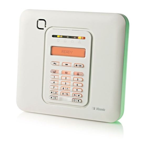
30 days. Wireless sirens can still provide 2 siren alarms before the siren becomes totally inactive. Note: When the ‘Low Battery’ message is received, the battery should be replaced within 7 days. PowerMaster-10 G2 Panel Indicator and Controls Figure 1a. PowerMaster-10 G2 Controls and Indicators LED Indicators Indication Function Power (Green): Indicates that your system is properly connected to the power outlet. -
Page 6: Control Keys
INTRODUCTION Control Keys Indication Function NEXT: Advance from item to item within a given menu. BACK: Move one step back within a given menu. OK: Review status messages one by one and also select a displayed option. Arming Keys Indication Function AWAY: Arming when nobody is at home HOME: Arming when people remain at home. -
Page 7: Control Keys
INTRODUCTION Indication Function Arm (Red): Lights when the system is in the armed state. Chime (Green): Chime zones will chime when disturbed (see Chapter 2). Trouble (Orange): Lights when the system is in a state of trouble (see Chapter 5). Control Keys Indication Function... -
Page 8: Built-In Alarm Sounder
INTRODUCTION Built-in Alarm Sounder The PowerMaster panel has a high power siren built-in that sounds in case of alarm to deter intruders and to summon help. The maximum operating time of the siren is configured by the installer according to local regulations. Continuously ON when initiated by a burglar zone or a 24-hour zone, and when a user initiates a “panic alarm”. -
Page 9: Screen Saver Mode
As a master User (User No.1) you will need a 4-digit security code to master the system (code 0000 is not allowed).You can also authorize 7 other persons (PowerMaster-10 G2) / 47 other persons (PowerMaster-30 G2) to use the system by providing them with their own security codes (see Chapter 6, B.4 Programming User Codes). -
Page 10: Operating The Powermaster System
For more information regarding terms used in this chapter, refer to APPENDIX C. GLOSSARY. Note: This manual displays PowerMaster-10 G2 panel buttons only, even when instructions refer to both panels. When an instruction refers to PowerMaster-30 G2 only, the PowerMaster-30 G2 panel buttons are displayed. -
Page 11: Disarming Under Duress
OPERATING THE POWERMASTER SYSTEM Disarming under Duress If you are forcibly compelled to disarm the system, enter the duress code (2580 by default) or another code set by the installer. Disarming will take place normally but a silent alarm will be transmitted to the monitoring station. Partition Selection Process Access to any desired partition is achieved through the use of an individual code or proximity tag. -
Page 12: Arming In The Latchkey Mode
“latchkey user”. Latchkey users are holders of user codes or users of keyfob transmitters 5 through 8 (PowerMaster-10 G2) / user codes 23-32 (PowerMaster-30 G2). The latchkey message is considered an alert and not an alarm, and is therefore sent to the private telephones programmed by the user as targets for alert messages. -
Page 13: Initiating Fire Alarm Or Emergency Alarm
OPERATING THE POWERMASTER SYSTEM PRESS RESULTING DISPLAY PANIC ALARM simultaneously READY HH:MM To stop the alarm, press the button and then key in your valid user code. Initiating Fire Alarm or Emergency Alarm You can generate a fire alarm or a silent emergency alarm in disarmed & armed states, as follows: PRESS RESULTING DISPLAY FIRE ALARM... -
Page 14: Speech And Sound Control
SPEECH AND SOUND CONTROL 3. Speech and Sound Control Speech & Sound Cont. Push-buttons The sound and speech-related functions offered by the control panel are controlled with the keypad, as detailed in the following list. When partitioning is enabled: Sound and speech-related features only apply to the partition(s) where the control panel is present. An activity performed via the control panel from another partition will be displayed and the LED will light. -
Page 15: Message Playback
SPEECH AND SOUND CONTROL Once the last of the boxes disappears, RECORDING ENDED will be displayed. When you release the button, the display will revert to the normal status-displaying mode, but will also indicate that a message is waiting. For example: READY HH:MM (alternating) -
Page 16: Electrical Appliance Control
ELECTRICAL APPLIANCE CONTROL 4. Electrical Appliance Control Control Options and Pushbuttons The system allows manual or automatic remote control of a device connected to the PGM output. The user defines the ON and OFF times via the Scheduler (see Chapter 6 - B.13 Programming the Scheduler). The installer determines which zone sensors will switch the remote controlled appliances on and off. -
Page 17: Reviewing Troubles And Alarm Memory
REVIEWING TROUBLES AND ALARM MEMORY 5. Reviewing Troubles and Alarm memory Alarm & Tamper Memory Indication The PowerMaster retains in its memory alarm and “tamper” events that occurred during the last arming period. Note: Alarm events are memorized only after the “abort period” (see Appendix C). This means that if you disarm the system immediately - before the abort period expires - there will be no memory indication A. -
Page 18: General Indications
REVIEWING TROUBLES AND ALARM MEMORY PRESS RESULTING DISPLAY PRESS RESULTING DISPLAY POWERMASTER-10 Z15 MISSING (alternating) Z09 LOW BATTERY Z15 MOTION SENS (alternating) (alternating) Z09 CONTACT LIVING ROOM (alternating) KITCHEN COMM. FAILURE READY HH:MM IMPORTANT! If the trouble beeps bother you, disarm the system again (even though it is already disarmed). This will cancel the trouble beeps for 4 hours. -
Page 19: Menus And Functions
2. Carefully read the section titled "Additional Information" according to the indicated references table at end of this section. Note: This manual displays PowerMaster-10 G2 control panel buttons only, even when instructions refer to both control panels. When an instruction refers to PowerMaster-30 G2 only, the PowerMaster-30 G2 control panel buttons are displayed. -
Page 20: Returning To The Previous Step Or Exiting The User Settings Menu
MENUS AND FUNCTIONS C. User Settings Options Menu Click until the display reads the desired setting option and then press Use to set the Zone Bypass Scheme i.e. to bypass (exclude) faulty or unsecured SET ZONE BYPASS ("disturbed") zones, or to clear a bypassed zone (unbypass). For further details and programming procedure see section B.1. -
Page 21: Buttons Used For Navigation & Setting
MENUS AND FUNCTIONS (see above) until the display reads [<OK> TO EXIT], or preferably, press once which brings you immediately to the exit screen [<OK> TO EXIT]. When the display reads [<OK> TO EXIT], press <OK> TO EXIT The system exits the [USER SETTINGS] menu and returns to the normal disarm READY 12:00 state while showing the READY display. -
Page 22: Reviewing The Zone Bypass Scheme
MENUS AND FUNCTIONS Z01: P1 P2 P3 Living Room Click the button until the display reads the zone you wish to bypass (or clear bypass), for example, "Z04" for Zone 04. After several Z04: NOT READY seconds the LED on the respective device starts flashing indicating "it's me". ... -
Page 23: Recalling The Zone Bypass Scheme
B.4 Programming User Codes PowerMaster system allows you to authorize up to 8 people (PowerMaster-10 G2) / 48 people (PowerMaster- 30 G2) to arm and disarm the system by providing each with a unique 4 digit personal security code, and assigning them with different security levels and functionalities. - Page 24 User Codes 2-4 (PowerMaster-10 G2) / User Codes 2-22 and 33-48 (PowerMaster-30 G2) are assigned to family members, co-workers etc. They enable arming and disarming of the system or of selected partitions as defined by the Master User.
-
Page 25: Add / Delete Proximity Tags
B.5 Add / Delete Proximity Tags A proximity tag may be assigned to each of the PowerMaster-10 G2 user codes 1-8 / PowerMaster-30 G2 user codes 1-32 that can be used instead of the user codes to perform a variety of functions, for example, arming, disarming, reading the event log, etc. - Page 26 Additional Information (section B.5) For detailed instructions on how to select User Settings – refer to section B.1 and section B.2. The display shows the first enrolled Tag (Tag No.1) of the 8 tags (PowerMaster-10 G2) / 32 tags (PowerMaster-30 G2).
-
Page 27: Add / Delete Keyfob Transmitters
(see section B.1 and section B.2), or quit programming (see section B.3). B.6 Add / Delete Keyfob Transmitters A portable keyfob transmitter may be assigned to each of the PowerMaster-10 G2 user codes 1-8 / PowerMaster-30 G2 user codes 1-32 for better, quicker and safer arming/disarming and other control functions. - Page 28 MENUS AND FUNCTIONS the first free number, and the keyfob's ID number; for example: [F01:Keyfob] alternating with [ID No. 300-5786]. ID No. 300-5786 To assign the keyfob to another user, for example, "User No. 5", key in [05] or alternatively click the button until the display reads F05:keyfob [F05:Keyfob] and then press...
-
Page 29: Setting The Time & Time Format
LED may blink for several seconds more while trying to establish communication. During this period of time the keyfob keys are disabled. The display shows the first enrolled Keyfob (Keyfob No.1) of the 8 keyfobs (PowerMaster-10 G2 / 32 keyfobs (PowerMaster-30 G2). -
Page 30: Setting The Date & Date Format
MENUS AND FUNCTIONS ☺ A "Happy Tune" sounds, the display reads the set time, returns to step 2 TIME 08:55A 6, 7 and then reads the selected time format. ☺ Return to step 2 Additional Information (section B.7) For detailed instructions on how to select User Settings –... -
Page 31: Enabling / Disabling Auto-Arming
MENUS AND FUNCTIONS on the first digit. You can move the cursor to the next or previous digit using the button. For the year, enter the two last digits only. You can now select another option in the User Settings menu (see section B.1 and section B.2), or quit programming (see section B.3). -
Page 32: Programming Private Phone And Sms Reporting
MENUS AND FUNCTIONS 12:00 PM The display shows the current setting of the Auto-Arm Time, for example, " ", with the cursor blinking on the first hour digit "1". For detailed explanation of how to set the time - refer to Section B.7 B. 08:30 A The saved auto arm time is displayed without the cursor, for example, "... - Page 33 MENUS AND FUNCTIONS B. To Program a Private Phone Click the button until the display reads the desired REPORTED EVENTS Telephone No. you wish to program or edit, for example, "2nd private tel#", and press 2nd private tel# To program or edit the phone number, at the blinking cursor position enter the ...
- Page 34 MENUS AND FUNCTIONS E. To Program the Acknowledge Method button until the display reads [Tel. acknowledge] Voice<- ->private Click the and press to confirm. Tel. acknowledge The display shows the currently selected option. by single ack Click the button until the display reads the desired acknowledge method, for example, "by all ack".
- Page 35 ". Using the buttons you can now select the events you wish to be reported to private telephones numbers according to the options provided in the tables below: PowerMaster-10 G2 Event Group Option Events to be reported alarms+alerts Alarm and alert messages...
-
Page 36: Enabling / Disabling The Squawk Option
MENUS AND FUNCTIONS If the control panel is PowerMaster-10 G2 or PowerMaster-30 G2 without Voice option, the display reads Redial attempts " ". You can now, select other options, end this session – (see section B.1 and section B.2), or quit programming (see section B.3). - Page 37 MENUS AND FUNCTIONS B. To Set the Day Sunday The 1 day of the scheduler is displayed. Click the button until the display reads the day you wish to schedule or "Daily", for example, "Tuesday". Tuesday When the "day" to schedule appears on the display, press C.
-
Page 38: Enabling / Disabling Voice Option
MENUS AND FUNCTIONS The screen also displays the selected time format. The display shows the current start or stop time setting of the selected activation with the cursor blinking on the first hour digit. If no time is programmed, the time display will be blank (- -:- - - ). For detailed explanation of how to set the time - refer to Section B.7 B. - Page 39 MENUS AND FUNCTIONS Additional Information (section B.14) For detailed instructions on how to select the Setting Options – refer to section B.1 and section B.2. enable prompts a. The display shows the currently selected setting (indicated by ), for example, " ".
-
Page 40: Event Reporting And Control By Telephone And Sms
* PowerMaster-30 G2 only Note: For UL installations, SMS is a supplementary feature. PowerMaster-10 G2 control panels In case of alarm the following voice signal will be sent to private telephones upon event reporting: (- - - - - - FIRE: ON - ON - ON - pause.. -
Page 41: Event Notifications By Sms
PowerMaster will disconnect the line. B. Executable Commands All Partitions Keying Sequence Command Single Partition Keying Sequence/PowerMaster-10 G2 Disarming [] [1] [#] [] [0] [partition] [1] [#] Arming Home [] [2] [#] [] ... -
Page 42: Remote Control By Sms
EVENT REPORTING & CONTROL BY TELEPHONE AND SMS All Partitions Keying Sequence Command Single Partition Keying Sequence/PowerMaster-10 G2 [] [0] [partition] [9] [#] Review status of specific partition 1, 2 (Voice version only) [] [5] [0] [0] [1] [#] [] ... - Page 43 The various SMS commands are detailed in the following table. In this table, “<code>” means a 4-digit user code and simply means blank space (see Note). SMS Command List All Partitions SMS format Command Individual Partition SMS Format/PowerMaster-10 G2 “AWAY <code>” “P# AWAY <code>” Arm AWAY “AW <code>”...
-
Page 44: Special Applications And Functions
SPECIAL APPLICATIONS AND FUNCTIONS 8. Special Applications and Functions Looking after People Left at Home In addition to acting as an alarm system, the PowerMaster can also be used to monitor the movement of people at home when the system is in the disarmed state (or even when armed “HOME” with perimeter protection only), and report lack of motion in interior zones if there is no detection of motion within predetermined time limits. -
Page 45: Testing The System
TESTING THE SYSTEM 9. Testing the System Periodic Test The components of your security system are designed to be maintenance-free as much as possible. Nevertheless, it is mandatory to test the system at least once a week and after an alarm event to verify that all system sirens, detectors, keyfobs, keypads and other peripherals function properly. - Page 46 TESTING THE SYSTEM The control panel reads the temperature of each zone. The display alternates Z01 24.5C between the temperature, the sensor number and the sensor location. Repeatedly click the button to review the temperature of each zone (by Temperature Sensor). Z01:Temp.
-
Page 47: Maintenance
AC power and this trouble state continues for more than a few hours, the battery may need to be replaced. An original Visonic battery must be used of which there are a number of types. For assistance in battery replacement, contact Technical Support. -
Page 48: Reading The Event Log
MAINTENANCE Reading the Event Log To read the event log, proceed as follows: READY 00:00 ENTER CODE: _ When the PowerMaster display reads [ENTER CODE: _], enter the current CODE master user code. LIST OF EVENTS The "Happy Tune" will sound and the PowerMaster display will read [LIST OF EVENTS]. -
Page 49: Appendix A. Functions Of Controlling Devices
APPENDICES APPENDIX A. FUNCTIONS OF CONTROLLING DEVICES A1. KP-160 PG2 Arming and Disarming the System Step Operation User Actions Keyboard & Panel Response Select a PARTITION Any combination of The selected key blinks. (if Partition is enabled) Arm AWAY The selected key and the "Present Prox Tag"... -
Page 50: A2. Kp-140/141 Pg2
APPENDICES A2. KP-140/141 PG2 Arming and Disarming the System Step Basic Arming User Actions Keypad & Panel Response Select a PARTITION The selected button lights. (Partition enabled) The selected button starts blinking Arm AWAY and prompts you to enter your "User Code"... -
Page 51: A3. Kf-234 Pg2
APPENDICES A3. KF-234 PG2 Keyfob Functionality Step Functions User Actions Response Arm AWAY When executing a command, the keyfob's LED blinks red once to indicate transmission of the command to Arm HOME the control panel. If the operation is successfully completed, the green LED lights momentarily and a Disarm (OFF) "happy tune"... -
Page 52: B3. The Show Function
APPENDICES Arming/Disarming a Single Partition To arm/disarm a single partition, press the button on the control panel and then press the Partition number: 1; 2; or 3. Then, press the button. B3. The Show Function The show function is enabled during single/all partition(s) status and displays information that is relevant to the selected or all partitions. -
Page 53: Appendix C. Glossary
APPENDICES APPENDIX C. GLOSSARY This list of terms is arranged in alphabetical order. Abort Period: When an alarm is initiated, the internal built-in sounder is activated first for a limited period of time which is the abort period set by the installer. If you cause an alarm accidentally, you can disarm the system within the abort period before the real sirens start and before the alarm is reported to the remote responders. - Page 54 APPENDICES still disturbed upon termination of the exit delay. Bypassed zones will not be protected throughout the arming period. Even if restored to normal (closed), bypassed zones will remain unprotected until the system is disarmed. Permission to “force arm” is given or denied by the installer while programming the system. HOME: This type of arming is used when people are present within the protected site.
-
Page 55: Appendix D. Home Fire Escape Planning
APPENDICES User Codes: The PowerMaster is designed to obey your commands, provided that they are preceded by a valid security access code. Unauthorized people do not know this code, so any attempt on their part to disarm or defeat the system is bound to fail. Some operations, however, can be carried out without a user code as they do not degrade the security level of the alarm system. -
Page 56: Appendix E. Specifications
APPENDICES APPENDIX E. SPECIFICATIONS E1. Functional PowerMaster-10 G2 PowerMaster-30 G2 Zones Number 30 wireless zones (including 1 hard-wired Up to 64 wireless zones, (including 2 hard- input). wired inputs). Hard-wired Zone 2.2 kE.O.L. resistance (max. resistance of 2.2 kE.O.L. resistance (max. resistance of wires 220 ... -
Page 57: E2. Wireless
APPENDICES PowerMaster-10 G2 PowerMaster-30 G2 Real Time Clock The control panel keeps and displays time and The control panel keeps and displays time and (RTC) date. This feature is also used for the log file by date. This feature is also used for the log file by... -
Page 58: E4. Communication
Local Computer Report 2 Monitoring Stations, 4 private telephones 2 Monitoring Stations, 4 private telephones Destinations Reporting Format SIA, Contact ID, Scancom, SIA IP, Visonic SIA, Contact ID, Scancom, SIA IP, Visonic Options PowerNet. PowerNet. Note: For UL Listed product, the... -
Page 59: E6. Peripherals And Accessory Devices
UL 985). APPENDIX F. COMPLIANCE WITH STANDARDS Compliance Statement Hereby, Visonic Group declares that the PowerG series of central units and accessories are designed to comply with: U.S. Standards: (FCC) CFR 47 part 15 and part 68, UL 1023 and UL 985 ... -
Page 60: Fcc Statement
If trouble is experienced with the “PowerMaster-10/30 G2” for repair or warranty information please contact Visonic Inc USA., 65 West Dudley Town Road, Bloomfield, CT 06002, phone number: 8 602 430 833, URL: www.visonic.com. If the equipment is causing harm to the telephone network, the telephone company may request to disconnect the equipment until the problem is resolved. - Page 61 This product is not to be thrown away with everyday waste. Directive 2002/96/EC Waste Electrical and Electronic Equipment. EMAIL: info@visonic.com INTERNET: www.visonic.com VISONIC LTD. 2013 POWERMASTER-10/30 G2 User's Guide D-303223 Rev 2 (3/13) D-303223 PowerMaster-10/30 G2 User's Guide...
- Page 62 USER GUIDE PowerMaster-30 G2 Fully supervised wireless alarm control system www.visonic.com...
Need help?
Do you have a question about the PowerMaster-10 G2 and is the answer not in the manual?
Questions and answers