
Related Manuals for Mallinckrodt INOmax DSIR Plus MRI


Summary of Contents for Mallinckrodt INOmax DSIR Plus MRI
- Page 1 Operation Manual (800 ppm INOMAX® (nitric oxide) for inhalation) Software version 3 series Part No. 20003 Rev - 01 Part No. 20568 Rev-02 2015-08...
- Page 2 Korean fonts Baekmuk Batang, Baekmuk Dotum, Baekmuk Gulim, and Baekmuk Headline are registered trademarks owned by Kim Jeong-Hwan. Mallinckrodt, the “M” brand mark and the Mallinckrodt Pharmaceuticals logo are trademark of a Mallinckrodt company. Other brands are trademarks of a Mallinckrodt company or their respective owner. ©2016 Mallinckrodt.
-
Page 3: Table Of Contents
Contents 1/ General Information ........................1-1 Indications for Use.......................... 1-1 Introduction to this Manual ......................1-2 INOmax DS Plus MRI Cart Operation ..................1-4 GaussAlert™ (gauss alarm) ......................1-8 INOmeter Operation ........................1-22 Theory of Operation ........................1-26 Environmental Effects ........................1-30 2/ Automated Pre-Use Checkout ...................... - Page 4 6/ Maintenance ............................. 6-1 User Maintenance Schedule ......................6-1 Testing the GaussAlert Function ....................6-2 Cleaning the INOmax DS Plus MRI ..................... 6-3 Replacing the O , NO and NO Sensors ..................6-7 Replacing the Water Separator Cartridge ..................6-9 Cylinder Leak Check ........................
- Page 5 Warnings tell the user about dangerous conditions that can cause injury to WARNING: the operator or the patient if you do not obey all of the instructions in this manual. Cautions tell the user how to properly use the equipment and conditions that could Caution: cause damage to the equipment.
- Page 6 Maintenance WARNING: • Handle and dispose of sensors according to facility biohazard policies. Do not incinerate. • If the MR injector module has been used in the wet/humidified part of the breathing circuit, it should be sterilized between each patient use. •...
- Page 7 Troubleshooting or Calibrating WARNING: • If an alarm occurs, safeguard the patient first before troubleshooting or repair procedures. • Abrupt discontinuation of INOMAX may lead to worsening oxygenation and increasing pulmonary artery pressure, i.e., Rebound Pulmonary Hypertension Syndrome. To avoid abrupt discontinuation, utilize the INOblender or integrated pneumatic backup if necessary.
- Page 8 Use in a MR Environment continued WARNING: • The gauss alarm will sound if the INOmax DS Plus MRI system is too close to the MR scanner. If alarm sounds, move system away from the MR scanner until the gauss alarm stops sounding. •...
-
Page 9: 1/ General Information
1/ General Information Part No. 20003 Rev - 01 Part No. 20568 Rev-02 2015-08... - Page 10 1/ General Information Part No. 20568 Rev-02 2015-08...
-
Page 11: Indications For Use
1/ General Information Indications for Use The INOmax DS Plus MRI delivery system is indicated for delivery of INOMAX (nitric oxide for inhalation) ® ® therapy gas into the inspiratory limb of the patient breathing circuit in a way that provides a constant concentration of nitric oxide (NO), as set by the user, to the patient throughout the inspired breath. -
Page 12: Introduction To This Manual
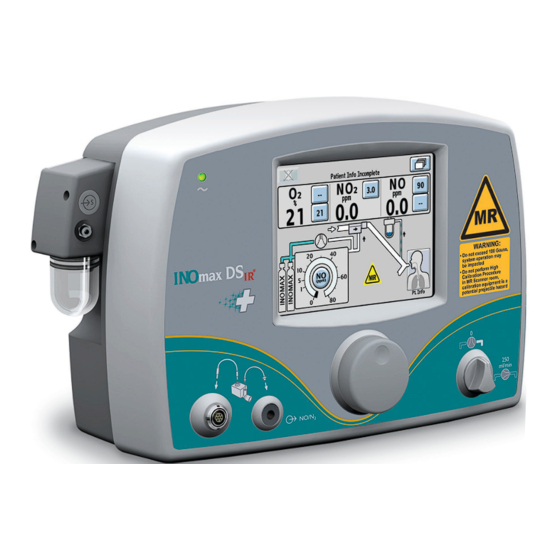
Introduction to this Manual Definitions and abbreviations % v/v % volume/volume. Auto-brake The mechanism which stops the INOmax DS Plus MRI cart from rolling. The yellow handle on the front of the INOmax DS Plus MRI cart that, when engaged, Auto-brake release allows the cart to roll. - Page 13 1. Sample Line Inlet 2. Main Power Indicator 3. Display Screen 4. Alarm Speaker (under front label) 5. Integrated Pneumatic Backup Switch 6. Control Wheel 7. MR Injector Module Tubing Outlet 8. MR Injector Module Cable Inlet 9. Water Bottle Figure 1-1 INOmax DS Plus MRI Front View 10.
-
Page 14: Inomax Ds Ir Plus Mri Cart Operation
INOmax DS Plus MRI Cart Operation • Always verify that the INOmax DS Plus MRI auto-brake is engaged after WARNING: positioning in the MR scanner room. • Always verify that the INOmax DS Plus MRI and INOblender are securely attached to the cart. •... - Page 15 Note: Pull the auto-brake handle up, toward the INOmax DS Plus cart handle, to disengage the auto-brakes. 1. INOmax DS Plus MRI 2. INOblender 3. Gauss Alarm (2) (see page 1-8) 4. Auto-brake Handle (see page 1-6) 5. Cylinder Mounting Strap 6.
- Page 16 1. Auto-brake Handle 2. Gauss Alarm (2) 3. Auto-brake Caster (2) 4. INOmax DS Plus MRI Mounting Bolt 5. INOblender MR Mounting Bolt 6. Tether Attachment Point Figure 1-4 INOmax DS Plus MRI and Cart Side View Part No. 20568 Rev-02 2015-08...
- Page 17 Always verify that the WARNING: INOmax DS Plus MRI and INOblender are securely attached to the cart. Figure 1-5 INOmax DS Plus MRI and Cart 1. INOmax DS Plus MRI Mounting Assembly 2. INOMAX Regulator (2) 3. INOmeter 4. Gauss Alarm (2) (see page 1-8) 5.
-
Page 18: Gaussalert™ (Gauss Alarm)
(100 gauss). Additional Information: • The GaussAlert functionality should be checked monthly (see Section 6/Maintenance). • Mallinckrodt will provide all maintenance for the GaussAlert. 1. Battery Indicator 2. Alarm Volume Adjustment 3. - Page 19 (Intentionally left blank) Part No. 20568 Rev-02 2015-08...
- Page 20 Navigating the Display Screens Note: The specific level is identified by the highlighted card on the Menu Button. Main Screen (first level) Recent Alarms Screen Patient Information Screen Menu Screen (second level) (second level) (second level) Navigating the Menu Screen (see page 1-11) 1-10 Part No.
- Page 21 Menu Screens (second level) Pre-Use Checkout Wizard Automated Purge Alarm History Low Calibration High Calibration Settings 1-11 Part No. 20568 Rev-02 2015-08...
- Page 22 Main Display Screen • On the main screen the user can view alarm messages, monitored values and graphical information. • By pressing the “Menu Button” on the touch screen (top right hand corner), the user can access the menu screen (see Figure 1-10). 1.
- Page 23 Settings Screen (third level) • The circuit flow graph, combined with calculated delivery graph, is a user level tool to ascertain NO delivery system limitations in the context of mechanical ventilation. • The circuit flow rate graph displays the real time peak and average flow rate in the breathing circuit over a 10 second time period, as measured by the MR injector module.
- Page 24 Display and user controls The INOmax DS Plus MRI has a color touch screen display and a control wheel for adjusting and entering user settings. The buttons on the touch screen and the control wheel perform a variety of functions using a three-step procedure (see “Setting and making changes on the INOmax DS Plus MRI”, page 1-16).
- Page 25 Main Screen Cylinder icons are not visible and the NO delivery setpoint button will remain inactive until the INOmax DS Plus MRI recognizes an INOMAX cylinder. High frequency and/or high intensity light Caution: emission, in the area of the INOmeter, may interfere with communication between the INOmax DS Plus MRI...
- Page 26 Setting and making changes on the INOmax DS Plus MRI Dose settings Displayed dose settings are 1, 5, 10, 20, 40, 60 and 80 ppm. Adjusting Parameters (example: dose setting) 1. SELECT (press) a button on the touch screen associated with the desired function.
- Page 27 3. CONFIRM the selection by pressing the control wheel or the button associated with the desired function again. A two minute monitoring Caution: alarm delay will prevent the low NO monitoring alarm from occurring while the measured values stabilize. • After confirming a desired Note: dose, the NO dose setting indicator will fill to the...
- Page 28 Settings Screen Adjustments Access the settings screen (third menu level). Display Brightness setting 1. Select the display brightness button on the touch screen. 2. Rotate the control wheel to indicate the display brightness level desired. Choices range from one (darkest) to 10 (brightest). 3.
- Page 29 Infrared Communication between the INOMAX Cylinders and the INOmax DS Plus MRI Loss of communication between the INOmax DS Plus MRI and the INOmeter WARNING: for more than one hour will result in interruption of INOMAX delivery. The INOmax DS Plus MRI has an interface using infrared (IR) technology which allows the INOmax DS Plus MRI to communicate with the INOmeter (which is mounted to each INOMAX cylinder).
- Page 30 External Light Interference High frequency and/or high intensity light emission, in the area of the INOmeter, may interfere Caution: with communication between the INOmax DS Plus MRI and the INOmeter on the INOMAX cylinder. If there is interference with the INOmax DS Plus MRI/INOmeter communication, the cylinder icon on the user screen will not be displayed and a "Cylinder Valve Closed"...
- Page 31 Loading INOMAX Cylinders Onto the INOmax DS Plus MRI Cart • The INOmax DS Plus MRI checks INOMAX cylinders for the correct product identity, cylinder Note: concentration and expiration date. • The INOmax DS Plus MRI recognizes the drug as expired on the first day of labeled expiration month on the INOMAX cylinder.
-
Page 32: Inometer Operation
INOmeter Operation • The INOmeter is a time-metric device which records the amount of time the INOMAX cylinder valve is opened. • When used with INOmax DS Plus MRI, two-way infrared (IR) communication occurs between the INOmax DS Plus MRI and the INOmeter. The INOmeter communicates the INOMAX cylinder concentration and the expiration date to the INOmax DS Plus MRI. - Page 33 3. Press lock downward to remove from the INOmeter (see Figure 1-15). 4. The cylinder must be closed to reinsert the lock. Align directly across from the iButton and press upward into socket to attach lock Figure 1-15 (see Figure 1-16). •...
- Page 34 When the cylinder valve is open and delivery is normal, the main screen shows the handle as green (see Figure 1-19). When two INOMAX cylinders are loaded Note: onto the cart and if both cylinder images do not appear on user screen, check to see if magnetic or light interference is suspected (see Section 4/ Alarms and Troubleshooting).
- Page 35 Symbols used in this manual or on the system Symbols replace words on the equipment and/or in this manual. These symbols include: Alarm Silence NO Gas Outlet 134˚C Autoclavable Average Flow Rate Peak Flow Rate Calculated Dose Greater than 20% of the Set Dose Pneumatic Inlet Calculated Dose Less than 20% of...
-
Page 36: Theory Of Operation
Theory of Operation The INOmax DS Plus MRI provides a constant dose a constant dose of INOMAX regardless of the of INOMAX into the inspiratory limb of the ventilator ventilator flow pattern or breath rate (see Figure circuit. The INOmax DS Plus MRI uses a “dual- 1-21). - Page 37 Figure 1-20 Schematic Diagram of INOmax DS Plus MRI Figure 1-21 INOMAX injection method provides a constant NO concentration 1-27 Part No. 20568 Rev-02 2015-08...
- Page 38 Effect of the INOmax DS Plus MRI in a ventilator circuit There are two main effects of connecting and using Minute Volume the INOmax DS Plus MRI in a ventilator breathing When using volume ventilation with the circuit. INOmax DS Plus MRI, the measured tidal volume 1.The INOmax DS Plus MRI adds NO/N...
- Page 39 Circle Anesthesia Ventilator Systems When intermittent inspiratory flow rates are used, peak ventilator flows which exceed 120 L/min The use of the INOmax DS Plus MRI with circle may be achieved. Peak inspiratory flow rates anesthesia ventilator systems (which use volume are transient and extremely short in duration.
-
Page 40: Environmental Effects
Environmental Effects Both these methods show that the exposure levels The National Institute for Occupational Safety and are significantly less than the levels recommended Health (NIOSH) have recommended exposure by NIOSH. limits as follows (Ref. 1). If the location for using NO has uncertain ventilation then the location should be evaluated for NO and NO build up prior to use. -
Page 41: 2/ Automated Pre-Use Checkout
2/ Automated Pre-Use Checkout Part No. 20003 Rev - 01 Part No. 20568 Rev-02 2015-08... - Page 42 2/ Automated Pre-Use Checkout Part No. 20568 Rev-02 2015-08...
- Page 43 2/ Automated Pre-Use Checkout Connect the INOmax DS Plus MRI power cord to a hospital-grade AC outlet. The power cord must always be connected to an electrical outlet to maintain a full battery charge. Keep the power cord off of the ground and away from moving parts. Caution: 1.
- Page 44 4. Pressing the NEXT button initiates the Pre-Use wizard. • Pressing the CANCEL button exits the Pre-Use wizard. If you cancel out of the Pre-use wizard, the manual pre-use checkout procedure can be found in Section 8/ Appendix. Part No. 20568 Rev-02 2015-08...
-
Page 45: Initial Connections
Initial connections Only use parts/ WARNING: accessories designated for use with this system. 1. Confirm the water bottle and water separator cartridge are in place Connect the patient gas sample line with Nafion to the sample line inlet port on the front of the INOmax DS Plus MRI Check cables and hoses for signs of wear and... - Page 46 4. Verify the power supply indicator is illuminated 5. Load two INOMAX drug cylinders onto cart and check for correct product identity labels, cylinder concentration (800 ppm) and expiration date. 6. Ensure the white plastic tip is not damaged. Replace if necessary. (see Replacing the tip on the INOMAX regulator, Section 6/ Maintenance).
- Page 47 8. Connect the INOMAX regulator hose to one of the INOMAX inlets 9. Connect the INOblender inlet hose to the INOmax DS Plus MRI INOblender outlet 10. Slide the quick-connect cover into place 11. Connect to a 50 psig oxygen supply hose to O inlet fitting on back of INOblender 12.
-
Page 48: High Pressure Leak Test And Automated Purge
High Pressure Leak Test and Automated Purge All INOmax DS Plus MRI devices must be purged before use to ensure the WARNING: patient does not receive an excess level of NO 1. Verify one of the high pressure regulators is connected to an INOMAX cylinder. - Page 49 5. Low Cylinder Pressure alarm may activate following purge sequence. 6. Open cylinder valve when purge is completed. If low calibration is still running after the Note: automated purge completes, wait for low calibration to complete. Part No. 20568 Rev-02 2015-08...
-
Page 50: Integrated Pneumatic Backup Inomax Delivery Test
Integrated Pneumatic Backup INOMAX Delivery Test 1. Assemble pre-use set-up connectors and tubing (press SHOW DIAGRAM button if needed). Set the oxygen flowmeter to 10 L/min. (#1 in Figure 2-1). 1. O Flowmeter (Connected to wall/tank) 2. O Tubing 3. 15M x 4.5 mm Adapter 4. -
Page 51: Performance Test
2. Turn the integrated backup INOMAX delivery to ON (250 mL/min.). Verify "Backup ON" alarm occurs. 3. Allow monitored values to stabilize (may take up to 3 minutes). Verify the NO and NO readings are within the following ranges: NO = 14-26 ppm ≤... -
Page 52: Inoblender Test
INOblender Test 1. Remove oxygen tubing from O flowmeter and connect to front of INOblender. 2. Remove the MR injector module from 40 ppm the pre-use set-up and reconnect the L/min adapters. 3. On the INOblender, set the INOMAX dose to 40 ppm and O flow to 10 L/min. -
Page 53: Depressurizing The Regulator Supply Line
Depressurizing the Regulator Supply Line To depressurize the INOMAX regulator supply line: 1. On the INOMAX cylinder, rotate the INOMAX cylinder handle clockwise to close the valve. 2. At the back of the INOmax DS Plus MRI, remove the regulator hose from the INOMAX gas inlet and connect it to the purge port. - Page 54 (Intentionally left blank) 2-12 Part No. 20568 Rev-02 2015-08...
-
Page 55: 3/ Patient Application
3/ Patient Application Part No. 20003 Rev - 01 Part No. 20568 Rev-02 2015-08... - Page 56 3/ Patient Application Part No. 20568 Rev-02 2015-08...
- Page 57 3/ Patient Application Before Operation Complete the initial connections and Pre-Use Checkout procedure as described in the previous sections before connecting the INOmax DS Plus MRI into the patient’s breathing circuit. (See the ventilator/breathing device manual for its setup and operation) •...
-
Page 58: Using The Inomax Ds Ir Plus Mri In The Mr Scanner Room
Using the INOmax DS Plus MRI in the MR Scanner Room • If the cart fails to move when the brake handle is pulled or moves when the brake WARNING: handle is not pulled, do not use the INOmax DS Plus MRI and contact your local representative. - Page 59 The gauss alarm will sound if the INOmax DS Plus MRI system is too close to the WARNING: MR scanner. If alarm sounds, move system away from the MR scanner until the gauss alarm stops sounding. 1. MR Scanner 2. MR Scanner Bore 3.
- Page 60 Connection to the ventilator breathing circuit The INOmax DS Plus MRI subtracts gas from the breathing circuit via the gas WARNING: sampling system at 230 mL per minute which can cause the ventilator to auto- trigger. Adjusting the flow sensitivity may be necessary. The trigger sensitivity of the ventilator should be checked after connecting the INOmax DS Plus MRI to the breathing circuit.
- Page 61 5. Select the dose button on the screen. On the INOmax DS Plus MRI, rotate the control wheel to set the NO dose. 6. Confirm the change by pressing the Control wheel or dose button on the screen. 7. Set the user-adjustable alarm settings on the INOmax DS Plus MRI and on the ventilator or breathing system.
-
Page 62: Inoblender Operation
INOblender Operation • The purge procedure must be followed to help ensure NO is purged from the WARNING: system before the manual resuscitator bag is connected to the patient. • The manual bag should be squeezed repeatedly during use to avoid NO building up in the bag. -
Page 63: Integrated Pnuematic Backup No Delivery
Integrated Pnuematic Backup NO Delivery • When using the integrated pneumatic backup with breathing circuit gas flows of WARNING: 5 L/min, the delivered NO dose will be approximately 40 ppm. Breathing circuit gas flows less than 5 L/min will deliver an NO dose greater than 40 ppm. •... - Page 64 This table indicates nominal NO concentrations delivered for different ventilator gas flows. Ventilator Gas Flow (L/min) NO Concentration (ppm) INOMAX cylinder conc. x 0.25 L/min / ventilator flow = estimated dose • When the pneumatic backup switch is turned OFF, the dose setting will automatically be returned to the previous dose that was set as well as the alarm set points (see Figure 3-5).
- Page 65 Cylinder Information • Only use a size “88” (1,963 liters) cylinder that is marked WARNING: “MR Conditional. Keep cylinder at 100 gauss or less.” with the INOmax DS Plus MRI while in the scanner room. Use of any other cylinder may create a projectile hazard. •...
-
Page 66: Changing Inomax Cylinders And Purging The Regulator Assembly
Changing INOMAX Cylinders and Purging the Regulator Assembly Caution: Replace an INOMAX cylinder when its pressure is less than 200 psig. 1. Check the INOMAX gas cylinders for the correct product identity, cylinder concentration, and expiration date. Verify cylinder has at least 500 psig and tighten the fitting to the INOMAX cylinder. - Page 67 3. Insert the NO/N quick-connect fitting into the purge port on the back of the INOmax DS Plus MRI and firmly push until the regulator pressure gauge reads zero (this purges any NO that has accumulated in the hose and regulator). All INOmax DS Plus MRI WARNING:...
- Page 68 5. Open the cylinder valve on the new cylinder (this may activate the “Two Cylinders Open” alarm until the empty cylinder valve is closed). 6. Close the cylinder valve on the empty cylinder and remove the supply line from the back of the INOmax DS Plus MRI.
-
Page 69: Oxygen Dilution Chart
Oxygen Dilution Chart For delivery with 800 ppm cylinder of INOMAX (nitric oxide) for inhalation (Illustrative Only) Set FiO 1.00 0.21 0.40 0.59 0.79 0.99 0.20 0.39 0.59 0.78 0.98 0.20 0.38 0.57 0.76 0.95 0.19 0.36 0.54 0.72 0.90 Actual FiO Caution FiO less than 0.21... -
Page 70: Duration Chart Inomax Cylinder 88-Size
Duration Chart INOMAX Cylinder 88-Size For an 88-Size 800 ppm Cylinder Concentration* (Illustrative Only) FLOW 5 L/min 10 L/min 20 L/min 40 L/min 39 Days 19.5 Days 9.8 Days 4.9 Days 19.4 Days 9.7 Days 4.8 Days 2.4 Days 9.6 Days 4.8 Days 2.4 Days 1.2 Days... - Page 71 Emptying the Water Bottle The water bottle (see Figure 3-8) collects fluids separated from the patient gas sample. • Empty and clean the water bottle before each patient use and empty whenever the bottle is more than half full. • Empty the water bottle routinely. Allowing it to fill and overflow may cause system errors. •...
- Page 72 Running on Battery • When operating on the battery, a battery icon ) is displayed on the screen along with the message “Running on Battery” ( ) in the text message area. • The low battery alarm will alert the user when there are approximately 30 minutes of battery life remaining.
- Page 73 Inspired Gas Sampling During Aerosol Delivery Caution: Pneumatic nebulizers will dilute the delivered INOMAX dose. To sample inspired gas during aerosol delivery: - Place the medication nebulizer downstream of the sample tee on the inspiratory limb (see Figure 3-9). This avoids over saturation of the water separator cartridge, or contamination of the sample system.
-
Page 74: Entering Patient Information
Entering Patient Information The following are instructions of how to use the patient identifier screen. Note: • Any identifier entered will be linked with each INOMAX cylinder used during treatment. A patient identifier and patient details can be entered at any time during the treatment of a patient by pressing the patient information button in the right-lower corner of the main screen. - Page 75 Pressing the keys on the keyboard allows the user to enter a sequential alphanumeric identifier. Prior to confirming the identifier, digits can be changed either by pressing the backspace button or pressing the digit that has been entered and typing over it. The CONFIRM button will illuminate when six characters have been entered.
- Page 76 Press the Select Diagnosis button and rotate the control wheel to select the patient diagnosis. Press the control wheel or button to confirm. Figure 3-15 Press the CONFIRM button to enter the patient details selected (see Figure 3-16). Figure 3-16 Prior to confirming the gestational age and birth weight (see Figure 3-17), digits can be changed either by pressing the backspace button...
- Page 77 Once the CONFIRM button has been Note: pressed, the patient details are stored (see Figure 3-18) and the identifier remains unchangeable until therapy is ended by turning the device to Standby (OFF). To access patient identifier information, press the patient information button on the main screen.
-
Page 78: Connection To Various Breathing Systems
Connection to Various Breathing Systems The INOmax DS Plus MRI must only be used in accordance with the indications, WARNING: usage, contraindications, warnings and precautions described in the INOMAX (nitric oxide) drug package inserts and labeling. Refer to this material prior to use. •... -
Page 79: Spontaneously Breathing Patient On A Nasal Cannula
Spontaneously Breathing Patient on a Nasal Cannula The INOmax DS Plus MRI can be used with a nasal cannula to deliver INOMAX concentrations from 5-80 ppm and an oxygen flow rate as low as two L/min. Conditioning of the oxygen flow prior to delivery through the MR injector module will help ensure the most accurate flow measurement. -
Page 80: Mr Conditional Ventilator Circuit
MR Conditional Ventilator Circuit WARNING: The INOmax DS Plus MRI subtracts gas from the breathing circuit via the gas sampling system at 230 mL per minute which can cause the ventilator to auto- trigger. Adjusting the flow sensitivity may be necessary. The trigger sensitivity of the ventilator should be checked after connecting the INOmax DS Plus MRI to the breathing circuit. -
Page 81: 4/ Alarms And Troubleshooting
4/ Alarms and Troubleshooting Part No. 20003 Rev - 01 Part No. 20568 Rev-02 2015-08... - Page 82 4/ Alarms and Troubleshooting Part No. 20568 Rev-02 2015-08...
- Page 83 4/ Alarms and Troubleshooting • Abrupt discontinuation of INOMAX may lead to worsening oxygenation and WARNING: increasing pulmonary artery pressure, i.e., Rebound Pulmonary Hypertension Syndrome. To avoid abrupt discontinuation, utilize the INOblender or integrated pneumatic backup if necessary. If Rebound Pulmonary Hypertension occurs, reinstate INOMAX therapy immediately.
- Page 84 Alarm Help High Priority Alarms All of these actions can be performed while delivering INOMAX to the patient: Alarm Possible Cause Recommended Action 1. High NO The High NO alarm level may Confirm High NO alarm limit is set appropriately. be inappropriately set.
- Page 85 High Priority Alarms All of these actions can be performed while delivering INOMAX to the patient: Alarm Possible Cause Recommended Action 2. Low NO The Low NO alarm setting Confirm Low NO alarm limit is set appropriately. may be inappropriately set. Circuit setup incorrect.
- Page 86 High Priority Alarms All of these actions can be performed while delivering INOMAX to the patient: Alarm Possible Cause Recommended Action 3. High NO The High NO alarm setting Confirm High NO alarm limit is set may be inappropriately set. appropriately.
- Page 87 High Priority Alarms All of these actions can be performed while delivering INOMAX to the patient: Alarm Possible Cause Recommended Action 5. Low O The Low O alarm setting may Confirm Low O alarm limit is set appropriately. be inappropriately set. The patient breathing circuit Check circuit for correct setup.
- Page 88 High Priority Alarms All of these actions can be performed while delivering INOMAX to the patient: Alarm Possible Cause Recommended Action 7. Cylinder Valve Closed INOMAX cylinder valve is Confirm INOMAX cylinder valve is fully open. closed. When two cylinders are 1.
- Page 89 High Priority Alarms All of these actions can be performed while delivering INOMAX to the patient: Alarm Possible Cause Recommended Action 9. Delivery Stopped MONITORED NO > 100 ppm Manually ventilate patient with the INOblender for at least 12 seconds. turn integrated pneumatic backup delivery ON.
- Page 90 High Priority Alarms All of these actions can be performed while delivering INOMAX to the patient: Alarm Possible Cause Recommended Action 12. Injector Module Fail Manually ventilate patient with the INOblender turn integrated pneumatic backup delivery ON. The MR injector module Disconnect and reconnect both ends of the injector module cable.
- Page 91 Low Priority Alarms All of these actions can be performed while delivering INOMAX to the patient: Alarm Possible Cause Recommended Action 16. Backup On The backup mode has been 1. Correct the reason for initiating integrated pneumatic backup delivery. turned ON. 2.
- Page 92 Low Priority Alarms All of these actions can be performed while delivering INOMAX to the patient: Alarm Possible Cause Recommended Action 21. Monitoring Failure Delivery of INOMAX continues during this alarm. Monitoring (sample) system 1. Remove from service. has failed. 2.
- Page 93 Additional Indicators Indicator Possible Cause Recommended Action 26. Battery Failure Device cannot communicate Contact Technical Support. with battery. 27. Set Dose is Zero, The set dose has been set to Close the INOMAX cylinder valve and Please Close Cylinder zero and the INOMAX cylinder depressurize regulator.
-
Page 94: Alarm Help
Alarm Help • If an alarm occurs, safeguard the patient first before troubleshooting or repair WARNING: procedures. • Use caution when troubleshooting the INOmax DS Plus MRI while in use for a patient. • When possible, replace the unit in question and perform troubleshooting procedure once the unit is removed from the MR scanner room. - Page 95 • Any alarm setpoint adjustments made will not be maintained when system power is Caution: cycled. • Default values will be used following a complete power loss (no AC main power and depleted battery). General alarm information Alarm silencing A listing of alarm messages is provided at the end of Pushing the Alarm Silence button this section.
- Page 96 User adjustable monitor alarms Do not set upper and lower alarm limits to extreme values, as this could reduce the Caution: effectiveness of the monitoring alarm system. Monitor alarm delay active indicator Monitor alarms for O , NO , and NO will be inactive anytime the Monitor Alarm Delay Active indicator is displayed.
-
Page 97: Alarm History
Alarm History When an alarm condition has been resolved, the Recent Alarms button alarm message is no longer displayed on the main screen. The recent alarms can be seen by pressing the Recent Alarms button. Figure 4-3 Recent Alarms Button on the Main Screen The Recent Alarms button is present and displayed as a “double-bell”... - Page 98 A complete list of all alarms that have occured since the INOmax DS Plus MRI has been turned ON can be viewed by pressing the Alarm History button on the menu screen (see figure 4-5). Figure 4-5 Menu Screen Priority A yellow dot signifies a low priority alarm, and a red dot signifies a high priority alarm.
-
Page 99: Gaussalert™ Alarm
GaussAlert™ Alarm The GaussAlert is designed to help keep MR Conditional equipment outside of the MR exclusion zone. GaussAlert is programmed to alarm when the preset magnetic field strength is exceeded. It produces a distinct audio alarm when MR Conditional equipment is placed too close to the MR magnet. - Page 100 (Intentionally left blank) 4-18 Part No. 20568 Rev-02 2015-08...
-
Page 101: 5/ Calibration
5/ Calibration Part No. 20003 Rev - 01 Part No. 20568 Rev-02 2015-08... - Page 102 5/ Calibration Part No. 20568 Rev-02 2015-08...
- Page 103 5/ Calibration Do not perform a high calibration procedure in the MR scanner room. Calibration WARNING: equipment is a potential projectile hazard. During any calibration process, all other alarms remain active while monitoring alarms are Note: disabled. To access the calibration menu: Press the menu button on the main screen to enter the menu screen (second menu level).
-
Page 104: Low-Range Calibration
Low-Range Calibration The low calibration of the monitor sensors uses room air to calibrate all three sensors at the same time. The system automatically draws in room air from an inlet port behind the water bottle, not the sample line. A low calibration is completed automatically when the INOmax DS Plus MRI is turned ON and during the following conditions:... - Page 105 3. When the low calibration is successful, a single tone will be heard and the main screen will appear. A two minute Monitor Alarm Delay Active indicator will occur, preventing monitoring alarms from occurring while the measured value stabilizes. All system alarms are still active. If the low calibration was unsuccessful, the INOmax DS Plus MRI will automatically...
-
Page 106: Oxygen Sensor High Calibration
Oxygen Sensor High Calibration Do not perform a high calibration procedure in the MR scanner room. Calibration WARNING: equipment is a potential projectile hazard. Never connect the sample line directly to a high pressure gas source (greater than Caution: 150 cmH O);... - Page 107 4. After reaching step 5 of the calibration wizard, the calibration will take approximately three minutes, during which a progress bar for the O sensor indicates progress. If the CANCEL button is pressed during Note: the high O calibration process, the calibration will be cancelled and the user will be returned to the high calibration screen.
- Page 108 If the calibration was unsuccessful, the O progress bar will turn red. • Attempt another calibration. To repeat the O high calibration, press Note: the START CAL button at the bottom of the screen. If the O sensor has failed, the display indicates the failed sensor symbol in the monitoring area of that sensor.
-
Page 109: No Sensor High Calibration
NO Sensor High Calibration Do not perform a high calibration procedure in the MR scanner room. Calibration WARNING: equipment is a potential projectile hazard. • When performing a high calibration, make sure to select the correct calibration gas (INOcal Caution: NO, 45 ppm, P/N BOM-COM-0150) and confirm the expiration date before using. - Page 110 6. Open the INOcal cylinder valve (turn counter- clockwise) to flow gas. To INOmax DS Plus MRI 6a. If the pressure is in the red or black zone (0- 25 psig) select another INOcal cylinder. 7. Attach tubing kit to patient gas sample line. If the date is flashing on the high Note: calibration screen, the calibration is...
- Page 111 After reaching step 7 of the high calibration wizard, the calibration will take approximately three minutes, during which a progress bar for the sensor indicates progress. If the CANCEL button is pressed during Note: the NO high calibration process, the calibration will be cancelled and the user will be returned to the high calibration screen.
- Page 112 When using the high calibration wizard, if the BACK button is pressed during the NO high calibration process, the progress bar will turn yellow, signifying a cancelled calibration. • Press the NEXT button to start the high calibration wizard. • Press the START CAL button to start the calibration again.
-
Page 113: 2 Sensor High Calibration
Sensor High Calibration Do not perform a high calibration procedure in the MR scanner room. Calibration WARNING: equipment is a potential projectile hazard. • When performing a high calibration, make sure to select the correct calibration gas (INOcal Caution: , 10 ppm, P/N BOM-COM-0162) and confirm the expiration date before using. •... - Page 114 To INOmax DS Plus MRI 6. Open the INOcal cylinder valve (turn counter- clockwise) to flow gas. 6a. If the pressure is in the red or black zone (0- 25 psig) select another INOcal cylinder. 7. Attach tubing kit to patient gas sample line. If the date is flashing on the high Note: calibration screen, the calibration is past...
- Page 115 After reaching step 7 of the high calibration wizard, the calibration will take approximately three minutes, during which a progress bar for the sensor indicates progress. If the CANCEL button is pressed during Note: the NO high calibration process, the calibration will be cancelled and the user will be returned to the high calibration screen.
- Page 116 When using the high calibration wizard, if the BACK button is pressed during the NO high calibration process, the progress bar will turn yellow, signifying a cancelled calibration. • Press the NEXT button to start the high calibration wizard. • Press the START CAL button to start the calibration again.
-
Page 117: 6/ Maintenance
6/ Maintenance Part No. 20003 Rev - 01 Part No. 20568 Rev-02 2015-08... - Page 118 6/ Maintenance Part No. 20568 Rev-02 2015-08...
-
Page 119: User Maintenance Schedule
6/ Maintenance User Maintenance Schedule Frequency Maintenance During Patient Use 1. Check the INOMAX cylinder pressure. A cylinder with less than 200 psig should be replaced. 2. Empty the water bottle as needed. Start of each Must perform the Pre-Use Procedure. patient Between each 1. -
Page 120: Testing The Gaussalert Function
Testing the GaussAlert Function • Keep the test magnet tool away from pacemakers, ICDs and other implanted WARNING: medical devices. • If either GaussAlert fails testing (does not alarm when the magnet tool is used), contact the Authorized Representative listed on the back cover of the operation manual to request a replacement INOmax DS Plus MRI system. -
Page 121: Cleaning The Inomax Ds Ir Plus Mri
Cleaning the INOmax DS Plus MRI • Do not autoclave or gas sterilize the INOmax DS Plus MRI. Caution: • Do not clean with the power connected and the INOmax DS Plus MRI turned ON. • Be sure that the INOmax DS Plus MRI is completely dry before using. - Page 122 Cleaning Agent Active Ingredients PDI Super Sani Cloth by PDI n-Alkyl (68% C12, 32% C14) dimethyl ethylbenzyl ammonium chlorides 0.25% n-Alkyl (60% C14, 30% C16, 5% C12, 5% C18) dimethyl benzyl ammonium chlorides 0.25% Isopropyl alcohol 55% Inert ingredients 44.50% Sani Cloth HB by PDI n-Alkyl (60% C14, 30% C16, 5% C12, 5% C18) dimethyl benzyl ammonium chlorides 0.07%...
- Page 123 Cleaning the GaussAlert™ Use a soft cloth dampened with water to clean the enclosure. Use an aqueous solution of up to 75% isopropyl alcohol for more efficient cleaning. Disinfection may be accomplished with the use of denatured alcohol. Cleaning the INOmeter •...
- Page 124 MR Injector Module Sterilizing and/or Disinfecting If the MR injector module was used in the wet/humidified part of the breathing WARNING: circuit, it should be sterilized between each patient use. Caution: Remove the the injector module cable prior to sterilizing or disinfecting the injector module. If the MR injector module has been used in the dry part of the breathing circuit, the MR injector module should be sterilized and/or disinfected in 70% ethyl alcohol after each patient use.
-
Page 125: Replacing The O 2 , No And No 2 Sensors
Replacing the O , NO and NO Sensors • Do not remove rear sensor cover in the MR scanner room due to potential WARNING: projectile hazard. • Handle and dispose of sensors according to facility biohazard policies. Do not incinerate. To replace any one of the three sensors: Remove the rear sensor cover by turning the two screws counterclockwise until loose... - Page 126 Replacing the O , NO and NO Sensors (cont’d) Replace the sensor cover and tighten the two screws clockwise (see Figure 6-6). Note: Newly Installed Sensor Time to Condition Prior to Calibration and NO 40 minutes 5 hours Insufficient conditioning will result in inaccurate gas readings.
-
Page 127: Replacing The Water Separator Cartridge
Replacing the Water Separator Cartridge The disposable water separator cartridge on the rear of the water bottle housing protects the monitoring system from moisture and other contaminants. To replace the Water Separator Cartridge: 1. Grasp the cartridge on the back and top edge and gently pull it up and out of the dovetail slot in the sampling block (see Figure 6-8). -
Page 128: Cylinder Leak Check
Cylinder Leak Check If a leak is suspected during the high pressure leak test (see Section 2/ Automated Pre-Use Checkout; High Pressure Leak Test), the following steps can be taken to check for leaks (see Figure 6-10 for possible cylinder gas leak locations) in the INOMAX regulator or INOMAX cylinder. -
Page 129: Preventative Maintenance
Preventative Maintenance Mallinckrodt performs the following maintenance task every year: • Replace O and NO sensors. Mallinckrodt performs the following maintenance task every two years: • Replace battery. • Check internal tubing. • Replace sample system tubing and filters. • Replace NO sensor. -
Page 130: Parts And Accessories
Parts and Accessories WARNING: Only use parts/accessories designated for use with this system. Parts/Accessories Part Number Alarm, GaussAlert™, 100 Gauss 80629 Calibration Gas, INOcal NO, 45 ppm BOM-COM-0150 Calibration Gas, INOcal NO , 10 ppm BOM-COM-0162 Calibration Tubing Kit 50239 Cart, INOmax DS Plus MRI 10076... - Page 131 Disposables Description Adapter 15M Fits 4.5 mm ID Tubing Adapter, 22F X 15M Adapter, 22M/15F X 22M/15F Adapter, Cuff, 22 mm ID X 22 mm ID Adapter, Gas Sample Tee Adapter, 90 degree Sample Port Disk Filter, 1.0 micron, glass fiber MR NO/N Injector Tube MR Patient Gas Sample Line (Nafion)
- Page 132 (Intentionally left blank) 6-14 Part No. 20568 Rev-02 2015-08...
-
Page 133: 7/ Product Specifications
7/ Product Specifications Part No. 20003 Rev - 01 Part No. 20568 Rev-02 2015-08... - Page 134 7/ Product Specifications Part No. 20568 Rev-02 2015-08...
- Page 135 7/ Product Specifications • The target patient population is controlled by the drug labeling for INOMAX and WARNING: is currently neonates. The INOmax DS Plus MRI is not intended to be used in other patient populations. • Outside of the United States, use of the INOmax DS Plus MRI is limited to the use in accordance with INOMAX nitric oxide for inhalation prescribing information as established with the national health authority.
- Page 136 230 mL/min Integrated Pneumatic Backup Delivery Integrated Pneumatic Backup Delivery = 250 mL/min Fixed Flow of NO/N Physical Delivery System (including: INOmax DSIR Plus MRI, INOblender, cart, 2 regulators and 2 INOMAX cylinders) Nominal Weight: 80 kg (176 lb) Nominal Width and Depth:...
- Page 137 Environmental Operating: Transport/Storage: Temperature: 5 to 40°C -20 to + 60°C 15 to 95% RH 15 to 95% RH Humidity: non-condensing non-condensing Ambient 57 to 110 kPa 57 to 110 kPa Pressure: Water Ingress IPX1 Protection: INOMAX Regulator Inlet Pressure: 14 to 155 Bar (200 to 2,248 psig) Outlet Pressure: 1.7 to 2.4 Bar (25 to 35 psig)
-
Page 138: Mr Signal-To-Noise Ratio And Artifact Dimension Analysis
GaussAlert™ Specifications Standard Factory Preset Alarm Thresholds: 100 Gauss (10mT) Audio Alarm Typical Sound Pressure: 92dB (A) at 24 inches Audio Alarm Frequency: 2900 Hz +/- 250Hz Typical Battery life: 5 years Sensor Type: Mechanical with panoramic uniform sensitivity MR Signal-to-Noise Ratio and Artifact Dimension Analysis In testing with gradient and radiofrequency (RF) intensive scan sequences provided by scanner manufacturers according to IEC 60601-2-33, a less than 0.2 cm geometric difference was observed in a spherical, Bayol-oil phantom. -
Page 139: Electromagnetic Compatibility Information
Electromagnetic Compatibility Information Guidance and Manufacturer’s Declaration – Electromagnetic Emissions The INOmax DS Plus MRI system (with GaussAlert™ alarms) is intended for use in the electromagnetic environment specified below. The user of the INOmax DS Plus MRI system should assure that it is used in such an environment. - Page 140 Guidance and Manufacturer’s Declaration – Electromagnetic Immunity The INOmax DS Plus MRI system (with GaussAlert™ alarms) is intended for use in the electromagnetic environment specified below. The user of the INOmax DS Plus MRI system should assure that it is used in such an environment.
- Page 141 Guidance and Manufacturer’s declaration - Electromagnetic Immunity INOmax DS Plus MRI system (with GaussAlert™ alarms) is intended for use in the electromagnetic environment specified below. The user of the INOmax DS Plus MRI system (with GaussAlert alarms) should assure that they are used in such an environment Immunity Test IEC 60601 test level Compliance Electromagnetic environment - guidance...
- Page 142 Recommended separation distances between portable and mobile RF communications equipment and the INOmax DS Plus MRI system (with GaussAlert™ alarms) The INOmax DS Plus MRI system is intended for use in an electromagnetic environment in which radiated RF disturbances are controlled. The user of the INOmax DS Plus MRI system can help prevent electromagnetic interference by maintaining a minimum distance between portable and mobile RF communications equipment (transmitters) and the INOmax DS...
-
Page 143: Rs 232 Data Output
RS 232 Data Output Enables serial communications for use with hospital electronic health record (EHR) system. Must be connected to the manufacturer-specified third-party hardware. • Do not use the RS 232 data output while in the MR scanner room. WARNING: •... - Page 144 Data output includes: • Device information - Model number, device generated identifier, software revision and user generated patient identifier • Monitored values - Monitored O , NO and NO • Settings - Dose setpoint - Alarm setpoints ▪ High O , low O , high NO , high NO and low NO...
-
Page 145: 8/ Appendix
8/ Appendix Part No. 20003 Rev - 01 Part No. 20568 Rev-02 2015-08... - Page 146 8/ Appendix Part No. 20568 Rev-02 2015-08...
-
Page 147: Manual Pre-Use Checkout
8/ Appendix Manual Pre-Use Checkout • Only use a size “88” (1,963 liters) cylinder that is marked “MR Conditional. WARNING: Keep cylinder at 100 gauss or less.” with the INOmax DS Plus MRI while in the scanner room. Use of any other cylinder may create a projectile hazard. •... - Page 148 5. Manual Purge/Alarm Verification: a. Press CANCEL to exit pre-use wizard (low calibration should be complete to continue). b. Verify INOMAX cylinder valve is closed. c. Set O flowmeter to 10 L/min. d. Purge INOmax DS Plus MRI. • Set the INOMAX dose to 40 ppm. •...
- Page 149 7. Performance Test: a. Verify O flowmeter is set to 10 L/min. b. Set INOMAX dose to 40 ppm. c. Verify monitored values: Acceptable NO Value (ppm) 35 - 45 Acceptable NO Value (ppm) < 1.5 Acceptable FiO 95 ± 3 d.
-
Page 150: Additional Dose Setting Information
Pre-Use Assembly 10 LPM 1. O Flowmeter 2. O Tubing 3. 15M x 4.5 mm Adapter 4. 22M / 15F x 22M / 15F Adapter 5. Injector Module 6. 300 mm of 22 mm hose 7. Patient Gas Sample Line with Nafion 8. -
Page 151: Bypassing The Inomax Ds Plus Mri And Connecting The Inoblender Directly To The Inomax Regulator
Bypassing the INOmax DS Plus MRI and Connecting the INOblender Directly to the INOMAX Regulator Typically the INOblender receives INOMAX from the INOmax DS Plus MRI (INOMAX cylinder supplies both devices; see Figure 8-2). INOMAX Oxygen Figure 8-2 As a stand-alone device INOMAX cylinder supplies just the INOblender. - Page 152 (Intentionally left blank) Part No. 20568 Rev-02 2015-08...
- Page 153 (Intentionally left blank) Part No. 20003 Rev - 01 Part No. 20568 Rev-02 2015-08...
- Page 154 Mallinckrodt Manufacturing LLC 6603 Femrite Drive, Madison, WI 53718-6801 USA 877-566-9466 www.inomax.com Part No. 20568 Rev-02 2015-08...
Need help?
Do you have a question about the INOmax DSIR Plus MRI and is the answer not in the manual?
Questions and answers