Table of Contents
Advertisement
Quick Links
SERVICE MANUAL
NPB-195 Pulse Oximeter
Caution: Federal law (U.S.) restricts this device to sale by or on the order of a physician.
To contact Mallinckrodt's representative: In the United States, call 1-800-635-5267 or 314-654-2000; outside the United States,
call your local Mallinckrodt representative.
© 2000 Mallinckrodt Inc. All rights reserved. 035154D-0100
Advertisement
Table of Contents
Troubleshooting

Related Manuals for Mallinckrodt NELLCOR NPB-195


Summary of Contents for Mallinckrodt NELLCOR NPB-195
- Page 1 NPB-195 Pulse Oximeter Caution: Federal law (U.S.) restricts this device to sale by or on the order of a physician. To contact Mallinckrodt's representative: In the United States, call 1-800-635-5267 or 314-654-2000; outside the United States, call your local Mallinckrodt representative.
- Page 2 4280 Hacienda Drive Pleasanton, CA 94588 USA Nellcor Puritan Bennett Inc. is a wholly owned subsidiary of Mallinckrodt Inc. Nellcor, Nellcor Puritan Bennett, Durasensor, and Oxisensor II are trademarks of Mallinckrodt Inc. To obtain information about a warranty, if any, for this product, contact Mallinckrodt's Technical Services or your local Mallinckrodt representative.
-
Page 3: Table Of Contents
TABLE OF CONTENTS List of Figures List of Tables Table of Contents ..................List of Figures................... List of Tables .................... Section 1: Introduction ................Manual Overview................NPB-195 Pulse Oximeter Description.......... Power-On Self Test..............Related Documents..............Section 2: Routine Maintenance ............... Cleaning .................. -
Page 4: Table Of Contents
Table of Contents Section 9: Specifications ................General ..................Electrical..................Physical Characteristics ............... Environmental ................Alarms ..................Factory Default Settings ............... Performance ................Section 10: Serial Port Interface Protocol..........10-1 10.1 Introduction .................. 10-1 10.2 Enabling the Serial Port..............10-1 10.3 Connecting to the Serial Port ............ -
Page 5: List Of Figures
Table of Contents LIST OF FIGURES Figure 1-1: NPB-195 Front Panel ..............Figure 1-2: User Softkey Map................ Figure 1-3: NPB-195 Rear Panel..............Figure 3-1: NPB-195 Controls ............... Figure 3-2: Self-Test Display ................. Figure 3-3: Adjusting %SpO2 Upper Alarm Limit .......... Figure 3-4: Adjusting % SpO2 Lower Alarm Limit ......... -
Page 6: List Of Tables
Table of Contents LIST OF TABLES Table 3-1: Dynamic Operating Range ............Table 3-2: Earth Leakage Current Limits ............. 3-10 Table 3-3: Enclosure Leakage Current Limits ..........3-11 Table 3-4: Patient Leakage Current Limits........... 3-11 Table 3-5: Patient Leakage Current Test Configurations - Mains Voltage on the Applied Part.......... -
Page 7: Section 1: Introduction
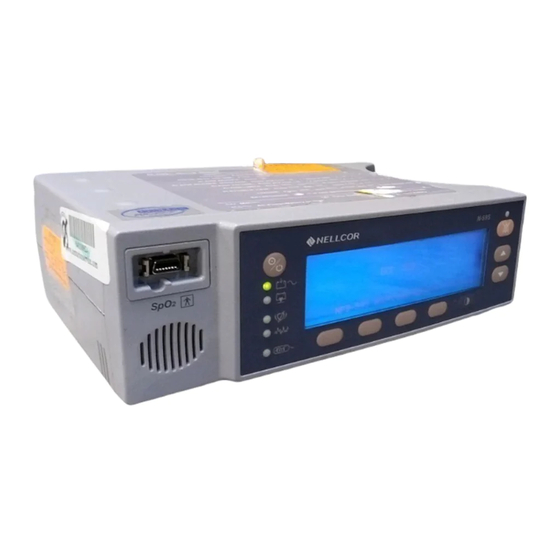
SECTION 1: INTRODUCTION 1.1 Manual Overview 1.2 NPB-195 Pulse Oximeter Description 1.3 Power-On Self Test 1.4 Related Documents MANUAL OVERVIEW This manual contains information for servicing the Nellcor model NPB-195 pulse oximeter. Only qualified service personnel should service this product. Before servicing the NPB-195, read the operator’s manual carefully for a thorough understanding of operation. - Page 8 Section 1: Introduction NPB-195 %SP02 LIMITS TREND SETUP LIGHT 1. SpO Sensor Port 9. Alarm Silence Button 2. Low Battery Indicator 10. Adjust Up Button 3. Power On/Standby Button 11. Adjust Down Button 4. AC/Battery Charging Indicator 12. Contrast Button 5.
- Page 9 Section 1: Introduction Normal %SPO2 Display Mode Limits Trend Setup Light LCD Display Light ON/OFF Next Exit View Clock Exit Return to Select alarm Return to Display Mode limit to be adjusted Display Mode High/Low Pleth Blip Exit %SpO2 or Pulse View Zoom Next...
-
Page 10: Power-On Self Test
If the start-up sequence is not completed as described above, do not use the monitor. The software version is often needed when calling Mallinckrodt's Technical Services Department or your local Mallinckrodt representative for technical assistance. Record the software version and have it available prior to requesting technical assistance. -
Page 11: Section 2: Routine Maintenance
BATTERY Mallinckrodt recommends replacing the instrument battery every 2 years. When the NPB-195 is going to be stored for 3 months or more, remove the battery prior to storage. To replace or remove the battery, refer to Section 6, Disassembly Guide. -
Page 13: Section 3: Performance Verification
It should also be performed before returning the instrument to use. Note: This section is written using Mallinckrodt factory-set defaults. If your institution has preconfigured custom defaults, those values will be displayed. Factory defaults can be restored using the configuration... - Page 14 Section 3: Performance Verification 3.3.1 Battery Charge Perform the following procedure to fully charge the battery. Connect the monitor to an AC power source. Verify that the monitor is off and that the AC Power/Battery Charging indicator is lit. Charge the battery for at least 14 hours in standby. 3.3.2 Power-up Performance The power-up performance tests (3.3.3.1 through 3.3.3.3) verify the following monitor functions:...
- Page 15 Section 3: Performance Verification Observe the monitor front panel. With the monitor off, press the Power On/Standby button. See Figure 3-1. The monitor must perform the following sequence. Within 2 seconds all LEDs are illuminated, then all pixels on the LCD display are illuminated, after which, the backlight comes on.
- Page 16 Section 3: Performance Verification Press the Limits softkey. Press and hold the Down Arrow button. Verify that the boxed number for %SpO upper alarm limit reduces to a minimum of “85.” Note: A decimal point in the display indicates that the alarm limits have been changed from factory default values.
- Page 17 Section 3: Performance Verification Press and hold the Down Arrow button. Verify that the boxed Pulse lower alarm limit display reduces to a minimum of “30.” Press and hold the Up Arrow button and verify that the boxed Pulse lower alarm limit display cannot be adjusted above the Pulse high limit of “40.”...
- Page 18 Section 3: Performance Verification Move the modulation switch on the SRC-2 to LOW. Verify the following monitor reactions: The plethysmograph waveform begins to track the artificial pulse signal from the SRC-2. The pulse tone is heard. Zeroes are displayed in the %SpO and Pulse displays.
-
Page 19: Table 3-1: Dynamic Operating Range
Section 3: Performance Verification 3.3.3.1.2 Alarm Volume Control After completing the procedure in paragraph 3.3.3.1.1 above: Press and hold the Alarm Silence button and verify the following: “OFF” is displayed for approximately 2 seconds. After 2 seconds, a steady tone is heard at the default alarm volume setting, the %SpO display indicates “VOL,”... - Page 20 Section 3: Performance Verification 3.3.3.1.5 Nurse Call Note: The Nurse Call tests must be performed with the instrument operating on AC power. Connect the negative lead of a voltmeter to pin 10 and positive lead to pin 11 of the serial port on the back of the instrument (Figure 10-1). Ensure that the audible alarm is not silenced or turned off.
-
Page 21: Safety Tests
Section 3: Performance Verification Slowly move the sensor LED in proximity to the photodetector element of the sensor. Verify, as the LED approaches the optical sensor, that the LED intensity decreases. Open the sensor and notice that the LED intensity increases. Repeat step 7 and the intensity will again decrease. -
Page 22: Table 3-2: Earth Leakage Current Limits
Section 3: Performance Verification 3.4.2 Electrical Leakage The following tests verify the electrical leakage of the monitor: • Earth Leakage Current • Enclosure Leakage Current • Patient Applied Risk Current • Patient Isolation Risk Current (Mains on Applied Part) Note: For the following tests, ensure that the AC switch on the rear of the instrument is configured for the AC voltage being supplied. -
Page 23: Table 3-3: Enclosure Leakage Current Limits
Section 3: Performance Verification Table 3-3: Enclosure Leakage Current Limits AC LINE NEUTRAL POWER IEC 601-1 AAMI/ANSI CORD LINE LINE CORD GROUND STANDARD CABLE Closed Closed Closed 100 µA 100 µA Closed Closed Open 500 µA 300 µA Closed Open Closed 500 µA 300 µA... -
Page 24: Table 3-5: Patient Leakage Current Test Configurations - Mains Voltage On The Applied Part
Section 3: Performance Verification 3.4.2.4 Patient Isolation Risk Current - (Mains Voltage on the Applied Part) This test is in compliance with AAMI Standard ES1 (patient isolation risk current [sink current]), and IEC 601-1 (patient leakage current). Patient Leakage Current is the measured value in a patient connection if mains voltage is connected to that patient connection. -
Page 25: Section 4: Power-On Settings And Service Functions
SECTION 4: POWER-ON SETTINGS AND SERVICE FUNCTIONS 4.1 Introduction 4.2 Power-on Settings 4.3 Service Functions INTRODUCTION This section discusses how to reconfigure power-on default values, access the service functions, and set the clock. POWER-ON SETTINGS The following paragraphs describe how to change power-on default settings. Through the use of softkeys shown in Figure 1-2, the user can change alarm limits, the type of display, baud rate, time and date, and trends to view. -
Page 26: Service Functions
4.3.1 Introduction Service functions can be used to select institutional defaults, and to access information about the patient or instrument. Only a Mallinckrodt Customer Service Engineer should access some of the items available through the service functions. These functions will be described in the text to follow. - Page 27 Section 4: Power-On Settings and Service Functions Figure 4-2 can be used as a quick reference showing how to reach different softkey functions. Items reached through the Param softkey can be accessed during normal operation. Functions provided by the Print and Next softkeys cannot be accessed when a sensor cable is connected to the instrument.
- Page 28 Section 4: Power-On Settings and Service Functions NPB-195 - - - %SP02 - - - RESET SAVE EXIT Figure 4-3: Param Softkeys RESET The Reset button can be used if alarm values stored in memory have been changed from factory default values. If Yes is pressed, the instrument sounds three tones and the alarm limits return to factory default values.
- Page 29 Section 4: Power-On Settings and Service Functions TREND A Trend printout will include all data recorded for up to 24 hours of monitoring since the last Clear data was performed. A trend line is recorded every 5 seconds or whenever an alarm condition has occurred. Figure 4-5 is an example of a Trend printout.
- Page 30 Section 4: Power-On Settings and Service Functions NPB-195 Version 1.0.0.000 Error Log Time: 14600:00:07 Op Time Error Task Addr Count 10713:21:03 48F9 00634:26:01 31A2 Output Complete Figure 4-6: Errlog Printout INSTAT A Delete softkey, described in the Operator's manual, allows the user to clear the most recent trend data.
- Page 31 Section 4: Power-On Settings and Service Functions 4.3.2.4 Next Additional options can be accessed from the main Service Functions menu by pressing the Next softkey. When Next is pressed, the softkeys change to the functions shown in Figure 4-8. NPB195 DOWNLD ALARMS NEXT EXIT...
-
Page 33: Section 5: Troubleshooting
WHO SHOULD PERFORM REPAIRS Only qualified service personnel should open the monitor housing, remove and replace components, or make adjustments. If your medical facility does not have qualified service personnel, contact Mallinckrodt's Technical Services or your local Mallinckrodt representative. REPLACEMENT LEVEL SUPPORTED The replacement level supported for this product is to the printed circuit board (PCB) and major subassembly level. -
Page 34: Troubleshooting Guide
Taking the recommended actions discussed in this section will correct the majority of problems you may encounter. However, problems not covered here can be resolved by calling Mallinckrodt's Technical Services Department or your local Mallinckrodt representative. Table 5-1: Problem Categories... -
Page 35: Table 5-2: Power Problems
Section 5: Troubleshooting 5.6.1 Power Power problems are related to AC and/or DC. Table 5-2 lists recommended actions to resolve power problems. Table 5-2: Power Problems Condition Recommended Action 1. Battery Low 1. Ensure that the NPB-195 is plugged into an indicator lights operational AC outlet and the AC indicator is on. -
Page 36: Table 5-3: Button Problems
Section 5: Troubleshooting 5.6.2 Buttons Table 5-3 lists symptoms of problems relating to non-responsive buttons and recommended actions. If the action requires replacement of a PCB, refer to Section 6, Disassembly Guide. Table 5-3: Button Problems Condition Recommended Action 1. The NPB-195 responds 1. -
Page 37: Table 5-5: Operational Performance Problems
Section 5: Troubleshooting 5.6.4 Operational Performance Table 5-5 lists symptoms of problems relating to operational performance (no error codes displayed) and recommended actions. If the action requires replacement of a PCB or module, refer to Section 6, Disassembly Guide. Table 5-5: Operational Performance Problems Condition Recommended Action 1. -
Page 38: Table 5-6: Serial Port Problems
Section 5: Troubleshooting 5.6.5 Serial Port Table 5-6 lists symptoms of problems relating to the serial port and recommended actions. If the action requires replacement of the PCB, refer to Section 6, Disassembly Guide. Table 5-6: Serial Port Problems Condition Recommended Action 1. -
Page 39: Error Codes
Section 5: Troubleshooting ERROR CODES An error code is displayed when the NPB-195 detects a non-correctable failure. When this occurs, the unit will stop monitoring, sound a low priority alarm that cannot be silenced, clear patient data from the display, and display an error code. Table 5-7 provides a complete list of error codes and possible solutions. -
Page 41: Section 6: Disassembly Guide
SECTION 6: DISASSEMBLY GUIDE 6.1 Introduction 6.2 Prior to Disassembly 6.3 Fuse Replacement 6.4 Monitor Disassembly 6.5 Monitor Reassembly 6.6 Battery Replacement 6.7 Power Entry Module Removal/Installation 6.8 Power Supply Removal/Installation 6.9 Cooling Fan Removal/Installation 6.10 Display PCB Removal/Installation 6.11 UIF PCB Removal/Installation 6.12 Alarm Speaker Removal/Installation INTRODUCTION The NPB-195 can be disassembled down to all major component parts,... -
Page 42: Fuse Replacement
Section 6: Disassembly Guide FUSE REPLACEMENT Complete procedure in paragraph 6.2. Disconnect the power cord from the back of the monitor. Remove the fuse drawer from the power module by pressing down on the tab in the center and pulling out as shown in Figure 6-1. Figure 6-1: Fuse Removal Put new fuses of equivalent size and rating in the drawer and reinsert the drawer in the power module. -
Page 43: Monitor Disassembly
Section 6: Disassembly Guide MONITOR DISASSEMBLY Set the NPB-195 upside down, as shown in Figure 6-2. Corner screws Figure 6-2: NPB-195 Corner Screws Remove the four corner screws. Caution: Observe ESD (electrostatic discharge) precautions when disassembling and reassembling the NPB-195 and when handling any of the components of the NPB-195. -
Page 44: Monitor Reassembly
Section 6: Disassembly Guide Power supply harness Figure 6-3: Separating Case Halves MONITOR REASSEMBLY Connect the Power Supply to J6 on the UIF PCB. Place the top case over the bottom case, being careful to align the lens, Power Entry Module, and the fan with the slots in the top case. Caution: When reassembling the NPB-195, tighten the screws that hold the cases together to a maximum of 10 inch-pounds. -
Page 45: Battery Replacement
Figure 6-4: NPB-195 Battery The lead-acid battery is recyclable. Do not dispose of the battery by placing it in the regular trash. Dispose of battery in accordance with local regulations or return to Mallinckrodt's Technical Services Department for disposal. Installation Connect the leads to the battery. - Page 46 Section 6: Disassembly Guide Equipotential Equipotential "L" on "N" on + Red -Black Figure 6-5: Internal Power Connections Complete the procedure in paragraph 6.5. Turn the monitor on and verify proper operation.
-
Page 47: Power Entry Module (Pem) Removal/Installation
Section 6: Disassembly Guide POWER ENTRY MODULE (PEM) REMOVAL/INSTALLATION Removal Complete the procedures in paragraphs 6.4. Push the top of the Power Entry Module (PEM) in from the outside of the case, and lift up. Use needle-nose pliers to disconnect the leads from the PEM (see Figure 6-6). -
Page 48: Power Supply Removal/Installation
Section 6: Disassembly Guide Position the AC lines from the PEM so that they do not come into contact with components on the Power Supply PCB. Complete procedure in paragraph 6.5. POWER SUPPLY REMOVAL/INSTALLATION Removal Complete the procedures in paragraphs 6.2 and 6.4. Complete steps 2 through 4 in paragraph 6.7. -
Page 49: Cooling Fan Removal/Installation
Section 6: Disassembly Guide Install the seven screws in the Power Supply and tighten. Connect the fan harness to J1 on the Power Supply. 10. Complete steps 4 through 6 in paragraph 6.7. 11. Complete procedure in paragraph 6.5. COOLING FAN REMOVAL/INSTALLATION Removal Complete the procedures in paragraphs 6.2 and 6.4. -
Page 50: Display Pcb Removal/Installation
Section 6: Disassembly Guide 6.10 DISPLAY PCB REMOVAL/INSTALLATION Removal Note: The LCD panel contains toxic chemicals. Do not ingest chemicals from a broken LCD panel. Complete procedures 6.2 and 6.4. Disconnect the CCFL harness (two white wires) from J5 of the UIF PCB. See Figure 6-9. -
Page 51: Uif Pcb Removal/Installation
Section 6: Disassembly Guide Separate the adhesive connection of the double-sided tape and lift the Display PCB up to remove it from the top case. Remove the used double-sided tape. Installation Install new double-sided tape located as shown in Figure 6-9. Slide the Display PCB into the grooves in the top case. - Page 52 Section 6: Disassembly Guide Figure 6-10: UIF PCB Installation Caution: When installing the UIF PCB, hand tighten the five screws to a maximum of 4 inch-pounds. Over-tightening could strip out the screw holes in the top case, rendering it unusable. Place the UIF PCB in the top case.
-
Page 53: Alarm Speaker Removal/Installation
Section 6: Disassembly Guide 6.12 ALARM SPEAKER REMOVAL/INSTALLATION Removal Complete the procedures in paragraphs 6.2 and 6.4. Disconnect the speaker wire harness from J13 on the UIF PCB (see Figure 6-11). Pull the retaining tab back from the speaker and lift the speaker out of the top case. -
Page 55: Section 7: Spare Parts
SECTION 7: SPARE PARTS 7.1 Introduction INTRODUCTION Spare parts, along with part numbers, are shown in Table 7-1. Item numbers correspond to the callout numbers in Figure 7-1. Table 7-1: Parts List Item Description Part No. Top Case Assembly (Membrane Panel Included) 048451 Fuse Drawer 691500... - Page 56 Section 7: Spare Parts Figure 7-1 shows the NPB-195 expanded view with numbers relating to the spare parts list. Figure 7-1: NPB-195 Expanded View...
-
Page 57: Section 8: Packing For Shipment
GENERAL INSTRUCTIONS Pack the monitor carefully. Failure to follow the instructions in this section may result in loss or damage not covered by any applicable Mallinckrodt warranty. If the original shipping carton is not available, use another suitable carton; North American customers may call Mallinckrodt's Technical Services Department to obtain a shipping carton. -
Page 58: Repacking In Original Carton
Section 8: Packing for Shipment REPACKING IN ORIGINAL CARTON If available, use the original carton and packing materials. Pack the monitor as follows: Place the monitor and, if necessary, accessory items in original packaging. Figure 8-1: Repacking the NPB-195 Place in shipping carton and seal carton with packing tape. Label carton with shipping address, return address and RGA number, if applicable. -
Page 59: Repacking In A Different Carton
Section 8: Packing for Shipment REPACKING IN A DIFFERENT CARTON If the original carton is not available, use the following procedure to pack the NPB-195: Place the monitor in a plastic bag. Locate a corrugated cardboard shipping carton with at least 200 pounds per square inch (psi) bursting strength. -
Page 61: Section 9: Specifications
SECTION 9: SPECIFICATIONS 9.1 General 9.2 Electrical 9.3 Physical Characteristics 9.4 Environmental 9.5 Alarms 9.6 Factory Default Settings 9.7 Performance GENERAL Designed to meet safety requirements of: UL 2601-1 CSA-C22.2 No. 601-1-M90, IEC 601-1 (Class I, type BF), ISO 9919, EMC per EN 60601-1-2. -
Page 62: Physical Characteristics
Section 9: Specifications PHYSICAL CHARACTERISTICS 9.3.1 Dimensions 3.3 in. H x 10.4 in. W x 6.8 in. D 8.4 cm H x 26.4 cm W x 17.3 cm D 9.3.2 Weight 5.7 lbs 2.6 kg ENVIRONMENTAL 9.4.1 Operating Temperature 5°C to 40°C (+41°F to +104°F) 9.4.2 Storage Temperature -20°C to +70°C (-4°F to +158°F) 9.4.3 Operating Altitude... -
Page 63: Factory Default Settings
Section 9: Specifications FACTORY DEFAULT SETTINGS Table 9-1: Default Settings Parameter Default Value High 100% Pulse Rate High 170 bpm Pulse Rate Low 40 bpm Alarm Volume Level 5 Alarm Silence Duration 60 seconds Alarm Silence Restriction Off with reminder Pulse Beep Volume Level 4 Baud Rate... -
Page 65: Section 10: Serial Port Interface Protocol
SECTION 10: SERIAL PORT INTERFACE PROTOCOL 10-1 Introduction 10-2 Enabling the Serial Port 10-3 Connecting to the Serial Port 10-4 Real-Time Printout 10-5 Trend Data Printout 10-6 Nurse Call 10.1 INTRODUCTION When a printer is connected to the serial port on the back of the NPB-195, a real- time printout can be obtained. - Page 66 Section 10: Serial Port Interface Protocol 9 10 11 12 13 14 15 Figure 10-1: Serial Port Pin Layout The serial cable can be a maximum of 25 feet and must be shielded. Connectors at both ends of the serial cable must have the shield terminated to the full 360 degrees of the connector’s metal shell.
- Page 67 Section 10: Serial Port Interface Protocol 10.4.1 Column Heading To explain the printout it will be necessary to break it down to its key components. The first two lines of the chart are the Column Heading shown below. Every 25th line is a Column Heading. A column heading is also printed whenever a value of the Column Heading is changed.
-
Page 68: Table 10-2: Status Codes
Section 10: Serial Port Interface Protocol 10.4.2.2 Patient Data NPB-195 VERSION 1.0.0.1 CRC: XXXX SpO2 Limit: 30-100% PR Limit: 100-180 bpm TIME %SpO2 Status 01-Jul-97 14:00:06 190* Patient data and the operating status of the unit are highlighted in the display above. -
Page 69: Trend Data Printout
Section 10: Serial Port Interface Protocol 10.5 TREND DATA PRINTOUT The format of data displayed when a trend printout is requested is similar to that of the real-time data. The only differences are that “TREND” is displayed in the top row instead of the “CRC:XXXX” software verification number, and there is no “Status”... -
Page 71: Section 11: Technical Supplement
SECTION 11: TECHNICAL SUPPLEMENT 11-1 Introduction 11-2 Oximetry Overview 11-3 Circuit Analysis 11-4 Functional Overview 11-5 AC Input 11-6 Power Supply Theory of Operation 11-7 Battery 11-8 User Interface PCB (UIF) 11-9 Front Panel Display PCB and Controls 11-10 Schematic Diagrams 11.1 INTRODUCTION This Technical Supplement provides the reader with a discussion of oximetry principles and a more in-depth discussion of NPB-195 circuits. -
Page 72: Circuit Analysis
Section 11: Technical Supplement Consequently, before comparing NPB-195 measurements with those obtained by an instrument that measures fractional saturation, measurements must be converted as follows: functional fractional saturation = saturation x 100-(% carboxyhemoglobin +%methemoglobin) 11.2.2 Measured Versus Calculated Saturation When saturation is calculated from a blood gas measurement of the partial pressure of arterial oxygen (PaO ), the calculated value may differ from the NPB-195 SpO... -
Page 73: Ac Input
Section 11: Technical Supplement The Display module includes the Membrane Panel and the LCD Display. The Membrane panel contains enunciators and push buttons, allowing the user to access information and to select various available parameters. The LCD Display PCB contains the LCD that presents the patient data. Power Power Supply Entry... -
Page 74: Battery
Section 11: Technical Supplement Two outputs from the bridge rectifier are used in the NPB-195. The fan control circuit uses the negative output. The positive output is the Main DC ranging from 7 to 18 VDC. This positive voltage is used for the battery circuit and to power the UIF PCB. -
Page 75: User Interface Pcb (Uif)
Section 11: Technical Supplement The 331 CPU on the UIF PCB monitors the charge level of the battery. If the voltage of the battery falls below 5.85 ± 0.1 VDC, a low battery alarm is declared. The instrument will continue monitoring and alarming for 15 minutes then power down. - Page 76 Section 11: Technical Supplement When the 331 sends a signal to the alarm speaker, three items are used to determine the tone that is sent. First, pulse tones change with the %SpO value being measured. The pulse beep tone will rise and fall with the measured %SpO .
- Page 77 Section 11: Technical Supplement 11.8.4 Input Conditioning Input to the SpO analog circuit is the current output of the sensor photodiode. In order to condition the signal current, it is necessary to convert the current to voltage. Because the IR and red signals are absorbed differently by body tissue, their received signal intensities are at different levels.
-
Page 78: Front Panel Display Pcb And Controls
Section 11: Technical Supplement The LCD will display real time when trends are selected. A time stamp is printed for each line of data on a printout. Real-time data is displayed and printed as Day, Month, Year, Hours, Minutes, and Seconds. 11.8.9 Patient Data Storage Patient data is stored once every 5 seconds. - Page 79 Section 11: Technical Supplement Figure 11-8: CPU Core Schematic Diagram A Figure 11-9: CPU Core Schematic Diagram B Figure 11-10: MC331 CPU Core Schematic Diagram A Figure 11-11: MC331 CPU Core Schematic Diagram B Figure 11-12: Display Driver Schematic Diagram Figure 11-13: Speaker Driver Schematic Diagram Figure 11-14: Core Power Supply Schematic Diagram Figure 11-15: Power On/Off Circuit Schematic Diagram...
- Page 81 VREF VREF 74HC00S 0.01U AD822 BYPASS +10V VREF 74HC00S IRLED/AV 0.01U PWM2 0.01U G_PWM2 G_MUX1 0.01U XO 12 VREF 88.7K_0.1% RED CHANNEL VREF +10V 0.1U TP10 0.12U G_REDDC 2.00K AD822 CD4053S VREF VREF +10V 51.1K 100K 100K 0.12U 220P +10V 1000P 1.00K 82.5K...
- Page 82 +10V VREF AD822 390P +10V DG201S G_LEDDR 3.32K 1.00M IR/RED IR/RED +10V 280K VREF 3.32K 182K 0.047U LED DRIVE 10.0K 0.01U 0.1U AD822 511K 2.74K 0.047U G_PWM2 VCC 16 MPSA56S G_PWM1 4.7P 2N3906S VREF 182K 10.0K 182K 100K TP18 LT1013S 2.74K 100K TP19...
- Page 83 ZERO-L G_REDDC REDDC DG201S BYPASS DG201S SPARES 3.32K 3.32K 0.01U 100K REDAC +10V +10V +10V Guard Ring +5.7V 0.47U 0.1U 0.015U 3216 CK06 LMC6044S 3.32K 0.01U VREF V- GND V- GND +10V 1000P 0.01U DG201S DG201S 0.01U 0.01U 7343 PWM0 12.1K REDLED/AV 100K...
- Page 84 RAW+10V VREF LPE-4841 MBRS130 VOUT 330P 0.1U GND1 GND3 7343 GND2 GND4 0.1U CR10 0.1U 78L05D 7343 1N914S GNDS 7343 7343 49.9 NFB 3 1000P TP22 +10V LT1373S MBRS130 49.9 TP16 +5.7V VREF HIGH CURRENT 4.99K 7343 10.0K 0.1U 2N3904S 7343 11.5K 36.5K...
- Page 85 SCHOTT 67129080 CLKDRV1 600R CLKDRV2 VPLUS C117 3300P 3300P CR11 600R SMCJ22C 1.0U 1.0U high power 1.0U 2200P clocks 4.02K I238 VMINUS CR12 TP29 I237 1N914 600R TP31 6N136 CR16 CR13 CR14 CR15 VPLUS BAV99 BAV99 BAV99 BAV99 VMINUS T1DIN T2DIN D1 2 RTRI...
- Page 86 4700P 196PWR I100 470P C102 AD[15:0] ADDRESS LATCHING 7343 I105 I107 VREF RAD0 ADDR0 I104 I106 I101 RAD1 ADDR1 RAD2 ADDR2 RAD3 ADDR3 0.1U VREF LEDDIS RAD4 ADDR4 ANGND RAD5 ADDR5 IR/RED REDDC RAD6 ADDR6 ACH0/P0.0 ADDR7 REDAC RAD7 ACH1/P0.1 RWD_RST IRDC RAD8...
- Page 87 ADDR[15:0] STATIC RAM I202 32KX8 I193 ADDR0 SRAMPWR ADDR1 ADDR2 ADDR3 C103 ADDR4 0.1U ADDR5 O0 11 ADDR6 7343 10.0K ADDR7 ADDR8 ADDR9 ADDR10 ADDR11 ADDR12 WR-L RD-L RAMEN-L 55257S I203 EPROMPWR EPROM C104 0.1U 64KX16 ADDR1 7343 ADDR2 ADDR3 ADDR4 ADDR5 ADDR6...
- Page 88 I279 R105 I210 VDDI VDD1 VDD2 RP12 VDD3 VDD4 VDD5 VDD6 C137 C122 C135 C133 C134 C125 C124 VDD7 0.1U 0.1U 0.1U 0.1U 0.1U 0.1U VDD8 0805 0805 0805 0805 0805 0805 I197 VDD9 I198 From Power Supply RP15 I306 I308 VDD10 RA10...
- Page 89 I295 I318 I319 C145 C119 0.1U 0.95U FLASHPWR 64KX16 A[16:0] A[16:0] A[16:0] FLASH PWR 44 RP13 D[0:15] RD10 RD11 RD12 TP55 RD13 R/WL RD14 BOOTFLSHL RD15 FLSHOEL RP14 GND1 GND2 34 I320 Flash Debug Code Debug Production 29C1024S I321 N195BOOT I322 ROMLATECSL RAMPWR...
- Page 90 I323 I324 I285 R140 CCFL inverter 4.02K 0.1U ASLEDDR 2N3906S R139 CR24 CR25 10.0K 1N4934 1N4934 CCFLPWR I284 100UH R141 BK-LT-ON SI9953 1 VDD 4.02K 2N3906S BIULEDDR HV_OUT I289 I290 C110 C142 R142 2 GND1 4.02K GND2 I288 2N3906S filter cap for 74HC32 PSLEDDR 7343 7343...
- Page 91 I199 C148 C149 C150 C151 0.1U TLC27L2 6.49K R132 PWM_FREQ 7343 7343 7343 7343 1.00K 4.99K GND1 VO1 5 I218 I200 I236 CON_2R R100 N.C. GND2 TLC27L2 10.0K 249K R133 PWM_VOL TDA7052A 1.00K R102 SPEAKER DRIVER 1.0U 100K 10.0K SI9953 RESETL TC7S00F I292...
- Page 92 TP13 CR17 3.3V MAIN_OUT MAIN_DC1 3_3V CR20 MBRS330T3 MBRS130 I215 LT1121CZ R113 R168 OUT 1 RAMPWR R112 CR35 100K 100K 1N914S 20.0K C109 C108 C111 1.0U CR34 R177 0.1U I291 10.0M 1N914S To Linear Power Supply R115 TP41 10.0K CR21 MBRS130 I214 LM393S...
- Page 93 I181 3_3V I175 R106 20.0K 3_3V 3_3V C143 10.0K R111 0.1U 100K 2N3904S I174 I112 CD4011B CD4011B CD4011B TP51 I180 TURN_OFF 2N3904S PWR_DLY From uP I185 I186 Active LOW TP50 3_3V C144 TP53 R134 I184 0.1U 20.0K I194 3_3V 3_3V PWR_CTRL R103 10.0K...
- Page 94 TOP SIDE BOTTOM SIDE Figure 11-16 UIF PCB Parts Locator Diagram 035263 11-37...
- Page 95 LINE LINE_IN Fan Control 18GA_BRN 2N3904 HIGH CURRENT VIAS MAIN_DC GBU8B 220P FAC+ 18GA _GRN/YEL 250V 115V 0.01U 2ASB MPSA56 To Fan 4700P 230V 250V CON_2L E3490A NEUTRAL 1.00K 1.00K 1/2W SMCJ22C 18GA_BLU 0.1U 1N4702 390K 15000U 1/2W 220P FAC- SMCJ22C EPS2PC3 250V...
- Page 96 "N" "L" "GND" "-" "+" Figure 11-18 Power Supply Parts Locator Diagram 035200 11-41...
-
Page 97: Section 12: Index
SECTION 12: INDEX Battery NPB-195 Desciption, 1-1 Replacement, 2-1 Nurse Call, 10-5 Battery Replacement, 6-5 Oximetry Overview, 11-1 Checks Functional, 2-1 Safety, 2-1 Circuit Analysis, 11-2 Packing for Shipment, 8-1 Cleaning, 2-1 Parts, Spare, 7-1 Codes, Error, 5-7 Performance Tests, 3-1 Alarm Limit Ranges, 3-3 Alarm Silence, 3-5 Alarm Volume, 3-7... - Page 98 Section 11: Technical Supplement Enclosure Leakage Current, 3-10 SAVE, 4-4 Ground Integrity, 3-9 SEL, 4-7 Patient Applied Risk Current, 3-11 TREND, 4-5 Patient Isolation Risk Current, 3-12 Spare Parts, 7-1 Saturation Specifications, 9-1 Calculated, 11-2 Default, 9-3 Fractional, 11-1 Electrical, 9-1 Functional, 11-1 Environmental, 9-2 Measured, 11-2...
Need help?
Do you have a question about the NELLCOR NPB-195 and is the answer not in the manual?
Questions and answers