
Related Manuals for WAGO 750-632


Summary of Contents for WAGO 750-632
- Page 1 Manual WAGO I/O System 750/753 750-632(/xxx-xxx) Proportional Valve Module Version 1.3.1, valid from FW/HW-Version 01/01...
- Page 2 We wish to point out that the software and hardware terms as well as the trademarks of companies used and/or mentioned in the present manual are generally protected by trademark or patent. WAGO is a registered trademark of WAGO Verwaltungsgesellschaft mbH. Manual Version 1.3.1, valid from FW/HW-Version 01/01...
-
Page 3: Table Of Contents
4.2.3.2 Push-in CAGE CLAMP Connectors 750-632/000-100 ....25 ® Display Elements ................26 Schematic Diagram ................28 4.4.1 Schematic Diagram 750-632 ............28 4.4.2 Schematic Diagram 750-632/000-100 ..........29 Technical Data .................. 30 4.5.1 Device Data .................. 30 4.5.2 Power Supply ................30 4.5.3... - Page 4 5.2.2 Specifying Setpoint Value: Operating Mode with Two Valves ..38 5.2.3 Specifying the Setpoint Value: Operating Mode with Two Valves, Coil Control: Two Coils, Unidirectional (3-wire) (750-632/000-100 only ....................38 Functions for the Setpoint Value Control ..........39 5.3.1 “Automatic mode”...
-
Page 5: Table Of Contents
8.4.1 Connection Example 1: 2 Valves (3-Wire) ........79 8.4.2 Connection Example 2: 1 Valve (3-Wire), 1 Valve (2-Wire) ....79 Commissioning ..................81 Configuration and Parameterization with WAGO-I/O-CHECK ..... 81 9.1.1 Parameterization Dialog ..............83 9.1.1.1 Toolbar ..................84 9.1.1.1.1... - Page 6 Table of Contents WAGO I/O System 750/753 750-632 Proportional Valve Module 11.1.3.1.1 Mailbox Commands ............109 11.1.3.1.2 Acknowledgement .............. 109 11.1.3.1.3 Signaling ................110 11.1.3.1.4 Finite Automation ............... 111 11.1.3.2 Data Exchange ............... 111 11.1.3.2.1 Example ................113 11.2 Protocols Supported by Mailbox 2.0 ..........114 11.2.1...
-
Page 7: Notes About This Documentation
Proportional Valve Module 750-632/000-100 Proportional Valve Module 2-3L The I/O module 750-632 shall only be installed and operated according to the instructions in this manual and in the manual for the used fieldbus coupler or controller. Consider power layout of the WAGO I/O System 750! In addition to these operating instructions, you will also need the manual for the used fieldbus coupler or controller, which can be downloaded at www.wago.com. -
Page 8: Symbols
Notes about this Documentation WAGO I/O System 750/753 750-632 Proportional Valve Module Symbols Personal Injury! Indicates a high-risk, imminently hazardous situation which, if not avoided, will result in death or serious injury. Personal Injury Caused by Electric Current! Indicates a high-risk, imminently hazardous situation which, if not avoided, will result in death or serious injury. - Page 9 WAGO I/O System 750/753 Notes about this Documentation 750-632 Proportional Valve Module Additional Information: Refers to additional information which is not an integral part of this documentation (e.g., the Internet). Manual Version 1.3.1, valid from FW/HW-Version 01/01...
-
Page 10: Number Notation
Notes about this Documentation WAGO I/O System 750/753 750-632 Proportional Valve Module Number Notation Table 2: Number Notation Number Code Example Note Decimal Normal notation Hexadecimal 0x64 C notation Binary '100' In quotation marks, nibble separated '0110.0100' with dots (.) -
Page 11: Important Notes
2.1.1 Subject to Changes WAGO GmbH & Co. KG reserves the right to provide for any alterations or modifications. WAGO GmbH & Co. KG owns all rights arising from the granting of patents or from the legal protection of utility patents. Third-party products are always mentioned without any reference to patent rights. -
Page 12: Technical Condition Of Specified Devices
These modules contain no parts that can be serviced or repaired by the user. The following actions will result in the exclusion of liability on the part of WAGO GmbH & Co. KG: •... -
Page 13: 2.1.4.1.2 Packaging
WAGO I/O System 750/753 Important Notes 750-632 Proportional Valve Module Environmentally friendly disposal benefits health and protects the environment from harmful substances in electrical and electronic equipment. • Observe national and local regulations for the disposal of electrical and electronic equipment. -
Page 14: Safety Advice (Precautions)
Important Notes WAGO I/O System 750/753 750-632 Proportional Valve Module Safety Advice (Precautions) For installing and operating purposes of the relevant device to your system the following safety precautions shall be observed: Do not work on devices while energized! All power sources to the device shall be switched off prior to performing any installation, repair or maintenance work. - Page 15 WAGO I/O System 750/753 Important Notes 750-632 Proportional Valve Module Inadequate wire cross sections can cause temperature increases! To avoid increasing thermal risks, only use conductor cross-sections sufficient for the required maximum load current. The conductor cross-sections specified in the technical data refer exclusively to the mechanical connection capacity of the clamping points.
- Page 16 Important Notes WAGO I/O System 750/753 750-632 Proportional Valve Module Do not reverse the polarity of connection lines! Avoid reverse polarity of data and power supply lines, as this may damage the devices involved. Avoid electrostatic discharge! The devices are equipped with electronic components that may be destroyed by electrostatic discharge when touched.
-
Page 17: Technology Of Proportional Valves
WAGO I/O System 750/753 Technology of Proportional Valves 750-632 Proportional Valve Module Technology of Proportional Valves Proportional valves can be used to control the throughput of liquids or gases. The throughput is determined by a lifting armature that is pressed on the valve seat by a spring. -
Page 18: Device Description
Device Description WAGO I/O System 750/753 750-632 Proportional Valve Module Device Description The I/O module serves to control proportional valves. The I/O module has two outputs with switchable dithering that can be current-controlled via pulse width modulation. A unidirectionally functioning coil or a bidirectionally functioning coil for a valve can be connected at each output. - Page 19 WAGO I/O System 750/753 Device Description 750-632 Proportional Valve Module The 750-632 module can be used with the fieldbus couplers and controllers of the WAGO I/O System 750 of the specified version or higher listed in the “Compatibility list” table.
-
Page 20: Table 4: Compatibility List 750-632
Device Description WAGO I/O System 750/753 750-632 Proportional Valve Module Table 4: Compatibility List 750-632 Fieldbus Bus System Item No. Firmware Couplers/Controllers Various PFC200 750-820x I/O-IPC 758-870/000-11x 758-874/000-11x 758-875/000-11x 758-876/000-11x The abbreviated parameter set is supported in firmware 18 or higher. -
Page 21: View
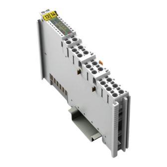
WAGO I/O System 750/753 Device Description 750-632 Proportional Valve Module View Figure 2: View Table 5: Legend for Figure “View” Pos. Description Details See Section Marking possibility with Mini- Status LEDs “Device Description” > “Display Elements” Data contacts “Device Description” > “Connectors”... -
Page 22: Connectors
Device Description WAGO I/O System 750/753 750-632 Proportional Valve Module Connectors 4.2.1 Data Contacts/Local Bus Communication between the fieldbus coupler/controller and the I/O modules as well as the system supply of the I/O modules is carried out via the local bus. The contacting for the local bus consists of 6 data contacts, which are available as self-cleaning gold spring contacts. -
Page 23: Power Jumper Contacts/Field Supply
The blade contacts are sharp-edged. Handle the I/O module carefully to prevent injury. Do not touch the blade contacts. The I/O module 750-632 has 2 self-cleaning power jumper contacts that supply and transmit power for the field side. The contacts on the left side of the I/O module are designed as blade contacts and those on the right side as spring contacts. -
Page 24: Push-In Cage Clamp ® Connectors
Device Description WAGO I/O System 750/753 750-632 Proportional Valve Module 4.2.3 Push-in CAGE CLAMP ® Connectors 4.2.3.1 Push-in CAGE CLAMP Connectors 750-632 ® Figure 5: Push-in CAGE CLAMP ® Connectors 750-632 Table 7: Legend for the “Push-in CAGE CLAMP ®... -
Page 25: Push-In Cage Clamp ® Connectors 750-632/000-100
WAGO I/O System 750/753 Device Description 750-632 Proportional Valve Module 4.2.3.2 Push-in CAGE CLAMP ® Connectors 750-632/000-100 Figure 6: Push-in CAGE CLAMP ® Connectors 750-632/000-100 Table 8: Legend for the “Push-in CAGE CLAMP Connectors 750-632/000-100” Figure ® Channel Designation Connection Function... -
Page 26: Display Elements
Device Description WAGO I/O System 750/753 750-632 Proportional Valve Module Display Elements Figure 7: Display Elements Table 9: Legend for Figure “Display Elements” Channel Designation LED State Function Yellow Active Dithering Inactive Yellow Setpoint value achieved Setpoint Setpoint value not achieved (e.g. - Page 27 WAGO I/O System 750/753 Device Description 750-632 Proportional Valve Module Table 9: Legend for Figure “Display Elements” Channel Designation LED State Function Green Logic „1“ Signal status DI 1 Logic „0“ Green Logic „1“ Signal status DI 2 Logic „0“...
-
Page 28: Schematic Diagram
Device Description WAGO I/O System 750/753 750-632 Proportional Valve Module Schematic Diagram 4.4.1 Schematic Diagram 750-632 Figure 8: Schematic Diagram 750-632 Manual Version 1.3.1, valid from FW/HW-Version 01/01... -
Page 29: Schematic Diagram 750-632/000-100
WAGO I/O System 750/753 Device Description 750-632 Proportional Valve Module 4.4.2 Schematic Diagram 750-632/000-100 Figure 9: Schematic Diagram 750-632/000-100 Manual Version 1.3.1, valid from FW/HW-Version 01/01... -
Page 30: Technical Data
Device Description WAGO I/O System 750/753 750-632 Proportional Valve Module Technical Data 4.5.1 Device Data Table 10: Technical Data ‒ Device Data Width 12 mm Depth (from upper edge of DIN 35 rail) 64 mm Height 100 mm Weight Approx. 50 g... -
Page 31: Outputs
WAGO I/O System 750/753 Device Description 750-632 Proportional Valve Module 4.5.5 Outputs Table 14: Technical Data ‒ Outputs Number and type 2 channels, PWM signal, bipolar (A+, A− and B+, B−) Features Output stage output, short-circuit-proof and protected against overload by... -
Page 32: Wiring
Device Description WAGO I/O System 750/753 750-632 Proportional Valve Module 4.5.6 Wiring Table 16: Technical Data ‒ Wiring Connection technology Push-in CAGE CLAMP ® Wire sizes Solid 0.08 mm² … 1.5 mm²/AWG 28 … 16 Fine-stranded 0.25 mm² … 1.5 mm²/AWG 22 … 16 Coil connections A+/A and B+/B-: 1.5 mm²/AWG 16... -
Page 33: Approvals
The following approvals have been granted to 750-632 I/O module: UL508 Korea Certification MSIP-REM-W43-PVM750 The following Ex approvals have been granted to the basic version of 750-632 I/O modules and the variation /000-100: TÜV 14 ATEX 148929 X II 3 G Ex nA IIC T4 Gc IECEx TUN 14.0035 X... -
Page 34: Standards And Guidelines
Device Description WAGO I/O System 750/753 750-632 Proportional Valve Module Standards and Guidelines The standard version of the 750-632 I/O module and the 750-632/000-100 version meet the following standards and guidelines: EMC Directive EMC CE-Immunity to interference EN 61000-6-2 EMC CE-Emission of interference... -
Page 35: Function Description
Function Description The I/O module can be operated with all compatible fieldbus couplers/controllers from the WAGO-I/O-SYSTEM 750. The I/O module can control proportional valves such that the valves can be precisely set in proportion to the current supplied. Hydraulic actuators, for example, can be controlled in this way. -
Page 36: Operating Mode With Two Valves
(4-wire) (3-wire) (4-wire) (3-wire) Uni- Uni- Uni- Uni- Uni- Uni- direc- direc- direc- direc- direc- direc- direc- direc- tional tional tional tional tional tional tional tional Functionality is only supported by version 750-632/000-100. Manual Version 1.3.1, valid from FW/HW-Version 01/01... -
Page 37: Specifying The Setpoint Value
WAGO I/O System 750/753 Function Description 750-632 Proportional Valve Module Specifying the Setpoint Value The control current provided by the I/O module can be directly specified in the process image (output) via a setpoint value. The current actual value is depicted by the I/O module in the process image (input) as the value of the current. -
Page 38: Specifying Setpoint Value: Operating Mode With Two Valves
Function Description WAGO I/O System 750/753 750-632 Proportional Valve Module 5.2.2 Specifying Setpoint Value: Operating Mode with Two Valves Table 21: Operating Mode with Two Valves Setpoint Coil control Setpoint Control value range value, value range reference Valve n One coil −100 …... -
Page 39: Functions For The Setpoint Value Control
WAGO I/O System 750/753 Function Description 750-632 Proportional Valve Module Functions for the Setpoint Value Control The I/O module offers the following functions, to be explained later: 5.3.1 “Automatic mode” In “Automatic Mode”, the I/O module approaches the specified setpoint value automatically with the selected ramp. -
Page 40: Jog Mode
Function Description WAGO I/O System 750/753 750-632 Proportional Valve Module 5.3.2 “Jog Mode” In this function, the I/O module changes the setpoint value until an applied signal is canceled. For example, a drive runs at a fixed speed in a fixed direction until a corresponding button is released. -
Page 41: Tip Mode
WAGO I/O System 750/753 Function Description 750-632 Proportional Valve Module 5.3.3 “Tip Mode” The “Tip mode” function is a variant of the “Jog mode” function. In this case, the change in current is not controlled by level. At a rising edge, the current is increased or decreased for a parameterizable time period. -
Page 42: Hold
Function Description WAGO I/O System 750/753 750-632 Proportional Valve Module 5.3.4 “HOLD” During a ramp, the current level can be maintained using the “HOLD” function. Figure 13: “HOLD” Function Table 26: “HOLD” Function Event Description/Behavior SPL_EN is set to “1”. -
Page 43: Stop
WAGO I/O System 750/753 Function Description 750-632 Proportional Valve Module 5.3.5 “STOP” The “STOP” function can be achieved during operations automatically guided by the I/O module by specifying “0” as the setpoint value. As a result, the I/O module approaches this setpoint value at a speed according to the currently valid ramp. -
Page 44: End Stop Behavior
Ramp stops. Present current level is achieved. maintained. 5.3.6 End Stop Behavior The end stop behavior can be configured from the tab or WAGO-I/O-CHECK. The respective parameters are described below: Table 28: End Stop Behavior Parameter Description Hold current value. -
Page 45: 5.3.6.1.1 Approach End Stop Value
WAGO I/O System 750/753 Function Description 750-632 Proportional Valve Module 5.3.6.1.1 Approach End Stop Value Figure 15: Approach End Stop Value Table 29: Approach End Stop Value Event Description/Behavior Set SPL_EN to “1” “Automatic mode” is activated. Change setpoint value Ramp starts. - Page 46 Function Description WAGO I/O System 750/753 750-632 Proportional Valve Module Change the setpoint manually! The end stop value must be reached before the setpoint can be manually changed in JOG mode! Configuring the end stop value correctly! The I/O module does not consider whether the end stop has been configured correctly.
-
Page 47: Hold Current Value ("Freeze")
WAGO I/O System 750/753 Function Description 750-632 Proportional Valve Module 5.3.6.1.2 Hold Current Value (“Freeze”) Figure 16: Hold Current Value (“Freeze”) Table 30: Hold Current Value (“Freeze”) Event Description/Behavior Set SPL_EN to “1” “Automatic mode” is activated. Change setpoint value Ramp starts. -
Page 48: End Stop Behavior In "Jog Mode" And "Tip Mode
Function Description WAGO I/O System 750/753 750-632 Proportional Valve Module 5.3.6.2 End Stop Behavior in “JOG Mode” and “TIP Mode” The end stop behavior is divided into: • Approach end stop value • Hold current value (“Freeze”) 5.3.6.2.1 Approach End Stop Value... -
Page 49: Table 31: Approach End Stop Value
WAGO I/O System 750/753 Function Description 750-632 Proportional Valve Module Table 31: Approach End Stop Value Event Description/Behavior Set SPL_EN to “0” “JOG mode” is activated. Present current level is maintained. Set JOG_POS to “1” Present current level is increased. -
Page 50: Hold Current Value ("Freeze")
Function Description WAGO I/O System 750/753 750-632 Proportional Valve Module 5.3.6.2.2 Hold Current Value (“Freeze”) Figure 18: Hold Current Value (“Freeze”) Table 32: Hold Current Value (“Freeze”) Event Description/Behavior Set SPL_EN to “0” “JOG mode” is activated. Present current level is maintained. -
Page 51: Substitute Value Strategy
The behavior can be configured as follows: • Section “Tables 50, 51 (Process Data Handling, Valve 1, Valve 2)” • Section “Configuration and Parameterization with WAGO-I/O-CHECK 5.3.7.1 Approach Substitute Value The substitute value can be approached in two ways: •... -
Page 52: Manual Mode In Case Of Error (Emergency Operation)
The behavior can be configured as follows: • Section “Tables 52, 53 (Output Stage Valve 1, Valve 2)” • Section “Configuration and Parameterization with WAGO-I/O-CHECK“ Manual Version 1.3.1, valid from FW/HW-Version 01/01... -
Page 53: Digital Inputs
WAGO I/O System 750/753 Function Description 750-632 Proportional Valve Module Digital Inputs The functions • “Digital input” • “Jog mode” • “Tip mode” • “HOLD” • “STOP” • “End stop behavior” can be controlled via the digital inputs DI1 and DI2 using corresponding parameterization. -
Page 54: Generating Setpoint Values
Function Description WAGO I/O System 750/753 750-632 Proportional Valve Module 5.4.1 Generating Setpoint Values The setpoint value can be influenced by various functions: • By direct setpoint value specification (see section “Specifying Setpoint Values”), • By activating the Jog mode or Tip mode (see the section “Functions”), and •... -
Page 55: Figure 19: Overview Of The Internal Information Flow
WAGO I/O System 750/753 Function Description 750-632 Proportional Valve Module Figure 19: Overview of the Internal Information Flow Table 34: Legend – Overview of the Internal Information Flow Designation Explanation Setpoint value specification Ramp generator Linearization Valve adjustment Nominal current... -
Page 56: Function Block: Ramp Generator
Function Description WAGO I/O System 750/753 750-632 Proportional Valve Module 5.5.1 Function Block: Ramp Generator The speed at which the electrical current follows the setpoint value specification is designated as the “ramp function”. The ramp generator serves, among other purposes, to protect the slower mechanical systems when the setpoint value is changed erratically. -
Page 57: Figure 21: Start Up Ramp 100% In 1 Ms
WAGO I/O System 750/753 Function Description 750-632 Proportional Valve Module Table 35: Resolution of the Nominal Current Nominal Current Resolution (%) Resolution (mA) 1000 mA 0.01% 0.1 mA Table 36: Correlation: Resolution – Time Value (Input) Current after 1 ms... -
Page 58: Function Block: Linearization
Function Description WAGO I/O System 750/753 750-632 Proportional Valve Module Figure 23: Start up Ramp 100% in 10,000 ms Table 37: Reference Values for Ramps Procedure Rising Ramps Falling Ramps Reference Value Direct specification Nominal current of setpoint value Setup mode... -
Page 59: Function Block: Valve Adjustment
WAGO I/O System 750/753 Function Description 750-632 Proportional Valve Module 5.5.3 Function Block: Valve Adjustment This function block is used to compensate for design-related differences between the magnets and the valve. The goal is to achieve the most linear connection possible between the process value and the volume flow. -
Page 60: Figure 27: Positive Overlap
Function Description WAGO I/O System 750/753 750-632 Proportional Valve Module • Positive overlap: The high overlap ensures the lowest possible leakage in the zero position. This type of overlap is used most commonly in proportional valves. Figure 27: Positive Overlap... -
Page 61: Exemplary Depiction Of The Characteristic Curve Compensation
WAGO I/O System 750/753 Function Description 750-632 Proportional Valve Module 5.5.4.1 Exemplary Depiction of the Characteristic Curve Compensation The following image clarifies characteristic curve compensation by means of an example: Figure 28: Characteristic Curve Compensation In the top part of the image, the characteristic curve is shown for a valve with positive overlap. -
Page 62: Function Block: Dither Generator
Function Description WAGO I/O System 750/753 750-632 Proportional Valve Module Table 39: Function Block: Nominal Current Variable Value Unit PA_NOMINAL_CURR 2000 Process value <Current> 5000 0.01% Target output current 1000 5.5.5 Function Block: Dither Generator Using this function block causes a reduction of the influence of static friction. This enables significant reductions in the response threshold and hysteresis. - Page 63 WAGO I/O System 750/753 Function Description 750-632 Proportional Valve Module Parameter #DG_RAMP_ON and #DG_RAMP_OFF The dither signal is only gradually supplied to the actual value during on and off switching. The temporal process is determined by switching a ramp on and off.
-
Page 64: Current Outputs For Valve Coils
Function Description WAGO I/O System 750/753 750-632 Proportional Valve Module 5.5.6 Current Outputs for Valve Coils As soon as the ambient temperature increases in the I/O module, the nominal current is reduced according to the following diagram: Figure 29: Current Carrying Capacity Curve... -
Page 65: Process Image
WAGO I/O System 750/753 Process Image 750-632 Proportional Valve Module Process Image The process image differs depending on the type of fieldbus: All Fieldbuses (except PROFIBUS and PROFINET) 6.1.1 Operating Mode with One Valve Table 40: Process Image Process Image... -
Page 66: Profibus And Profinet
Process Image WAGO I/O System 750/753 750-632 Proportional Valve Module PROFIBUS and PROFINET 6.2.1 Operating Mode with One Valve Table 42: Process Image Process Image Input Output Byte 0 K-Bus-Statusbyte S0 Byte 0 RESERVED Byte 1 V1_STATUS Byte 1 V1_CONTROL... -
Page 67: Table 45: Status Byte S0
WAGO I/O System 750/753 Process Image 750-632 Proportional Valve Module Table 45: Status Byte S0 Status Byte S0 Bit 7 Bit 6 Bit 5 Bit 4 Bit 3 Bit 2 Bit 1 Bit 0 REG=0 ERR_CH2 ERR_CH1 ERR_MO REG=1 REGCOM_UPSTREAM... -
Page 68: Table 46: Control Byte C1 Or C2
Process Image WAGO I/O System 750/753 750-632 Proportional Valve Module Table 46: Control Byte C1 or C2 Control Byte C1 or C2 Bit 7 Bit 6 Bit 5 Bit 4 Bit 3 Bit 2 Bit 1 Bit 0 JOG_POS JOG_NEG... -
Page 69: Table 48: Status Byte S1
WAGO I/O System 750/753 Process Image 750-632 Proportional Valve Module Table 48: Status Byte S1 Status Byte S1 Bit 7 Bit 6 Bit 5 Bit 4 Bit 3 Bit 2 Bit 1 Bit 0 JOGPOS_ JOGNEG_ DITHER_S READY TARGET JOGPOS_... -
Page 70: Representation Of Target And Actual Values
Process Image WAGO I/O System 750/753 750-632 Proportional Valve Module Representation of Target and Actual Values Table 50: Representation of Target and Actual Values Short Description Setpoint Value Actual Value Target value V1_TARGET, V1_ACTUAL, V2_TARGET V1_ACTUAL Data type INT16 INT16... -
Page 71: Mounting
WAGO I/O System 750/753 Mounting 750-632 Proportional Valve Module Mounting Do not work when devices are energized! High voltage can cause electric shock or burns. Switch off all power to the device prior to performing any installation, repair or maintenance work. -
Page 72: Mounting Sequence
Always plug a bus end module (e.g. 750-600) onto the end of the fieldbus node! You must always use a bus end module at all fieldbus nodes with WAGO I/O System 750 fieldbus couplers or controllers to guarantee proper data transfer. -
Page 73: Removing The I/O Module
WAGO I/O System 750/753 Mounting 750-632 Proportional Valve Module Figure 30: Inserting I/O Module (Example) Press the I/O module into the assembly until the I/O module snaps into the carrier rail. Figure 31: Snap the I/O Module into Place (Example) Check that the I/O module is seated securely on the carrier rail and in the assembly. -
Page 74: Figure 32: Removing The I/O Module (Example)
Mounting WAGO I/O System 750/753 750-632 Proportional Valve Module Figure 32: Removing the I/O Module (Example) Electrical connections for data or power jumper contacts are disconnected when removing the I/O module. Manual Version 1.3.1, valid from FW/HW-Version 01/01... -
Page 75: Connect Devices
Do not connect more than one conductor at one single connection! If more than one conductor must be routed to one connection, these must be connected in an up-circuit wiring assembly, for example using WAGO feed- through terminals. Terminate both solid and stranded or ferruled conductors by simply pushing them in - no tool required. -
Page 76: Power Supply For Marine Applications
750-624 Filter Module or to other 750-632 modules. Only a bus module without power jumper contacts (e.g., supply, filter or end module) shall be connected to the right side of the 750-632 module(s). -
Page 77: Connection Examples 750-632
WAGO I/O System 750/753 Connect Devices 750-632 Proportional Valve Module Connection Examples 750-632 8.3.1 Connection Example 1: 2 Valves (2-Wire) Figure 35: Connection Example 1: 2 Valves (2-Wire) 8.3.2 Connection Example 2: 1 Valve (4-Wire) Figure 36: Connection Example 2: 1 Valve (4-Wire) Manual Version 1.3.1, valid from FW/HW-Version 01/01... -
Page 78: Connection Example 3: 1 Valve (3-Wire)
Connect Devices WAGO I/O System 750/753 750-632 Proportional Valve Module 8.3.3 Connection Example 3: 1 Valve (3-Wire) Figure 37: Connection Example 3: 1 Valve (3-Wire) Manual Version 1.3.1, valid from FW/HW-Version 01/01... -
Page 79: Connection Examples 750-632/000-100
WAGO I/O System 750/753 Connect Devices 750-632 Proportional Valve Module Connection Examples 750-632/000-100 8.4.1 Connection Example 1: 2 Valves (3-Wire) Figure 38: Connection Example 1: 2 Valves (3-Wire) 8.4.2 Connection Example 2: 1 Valve (3-Wire), 1 Valve (2-Wire) Figure 39: Connection Example 2: 1 Valve (3-Wire), 1 Valve (2-Wire) Manual Version 1.3.1, valid from FW/HW-Version 01/01... - Page 80 Higher shielding performance is achieved when the connection between shield and ground is low resistance. To achieve this, connect the shield over a large surface area, for example, by using a WAGO shield connecting system. Manual Version 1.3.1, valid from FW/HW-Version 01/01...
-
Page 81: Commissioning
Manual valve positioning • Monitoring WAGO-I/O-CHECK You can obtain the WAGO-I/O-CHECK software on a CD under Item No. 759-302. This CD contains all the application program files and an explanation. You can find a description at the internet page at http://www.wago.com Manual... -
Page 82: Figure 40: Wago-I/O-Check User Interface
Commissioning WAGO I/O System 750/753 750-632 Proportional Valve Module In order to open specific parameterization dialogs for the I/O module, proceed as follows: Right click on the I/O module. Select the Settings menu item (see following figure Figure 40: WAGO-I/O-CHECK User Interface The parameterization dialog opens. -
Page 83: Parameterization Dialog
WAGO I/O System 750/753 Commissioning 750-632 Proportional Valve Module 9.1.1 Parameterization Dialog The parameterization dialog is divided into the following areas: Figure 41: Parameterization Dialog for the I/O Module Table 52: Legend for the “Parameterization Dialog for the I/O Module”... -
Page 84: Toolbar
Commissioning WAGO I/O System 750/753 750-632 Proportional Valve Module 9.1.1.1 Toolbar The toolbar is divided into the following areas in the parameterization dialog for the I/O module: • Main menu • Application menu 9.1.1.1.1 Main Menu The toolbar in the main menu contains the following buttons:... - Page 85 WAGO I/O System 750/753 Commissioning 750-632 Proportional Valve Module Table 53: Buttons on the Main Menu Button Function Description [Write all] Writes all parameters into the I/O module (see “Parameter Table” in the appendix). [Save remanent] Saves all parameters of the I/O module in the retentive memory (see “Parameter...
-
Page 86: 9.1.1.1.2 Application Menu
Commissioning WAGO I/O System 750/753 750-632 Proportional Valve Module 9.1.1.1.2 Application Menu The application menu is called up via the blue button to the left in the toolbar, and contains the following buttons: Figure 43: Buttons in the Application Menu... -
Page 87: Navigation Area
WAGO I/O System 750/753 Commissioning 750-632 Proportional Valve Module 9.1.1.2 Navigation Area In the navigation area, there are eight different buttons that can be used to configure the I/O module: • “Operating Mode” menu item • “Module Parameters” menu item •... -
Page 88: 9.1.1.3.1 "Operation Mode" Menu Item
Commissioning WAGO I/O System 750/753 750-632 Proportional Valve Module 9.1.1.3.1 “Operation Mode” Menu Item Individual variants can be selected using this menu item: Figure 44: “Operation Mode” Menu Item Table 55: “Operating Mode” – Settings Menu Item Option Valve 1... -
Page 89: Figure 45: Operation Mode" Menu Item (750-632/000-100)
WAGO I/O System 750/753 Commissioning 750-632 Proportional Valve Module The I/O module 750-632/000-100 has advanced setting possibillities. These are described below: Figure 45: Operation Mode” Menu Item (750-632/000-100) Table 56: “Operating Mode” – Advanced Setting Menu Item Option Valve 1... -
Page 90: 9.1.1.3.2 "Module Parameters" Menu Item
Commissioning WAGO I/O System 750/753 750-632 Proportional Valve Module 9.1.1.3.2 “Module Parameters” Menu Item Various I/O module parameters can be set using this menu item: Figure 46: “Module Parameters” Menu Item Table 57: “Module parameters” menu item Option Description Tipp Mode TIP Time The time period for TIP mode can be defined. - Page 91 WAGO I/O System 750/753 Commissioning 750-632 Proportional Valve Module Table 57: “Module parameters” menu item Option Description Actual Value Selector The user can select here in what format the actual value is output. The (Valve 1/Valve 2) “with filter” information specifies that the actual value is filtered with activated “Dither Function”.
-
Page 92: 9.1.1.3.3 "Digital Inputs" Menu Item
Commissioning WAGO I/O System 750/753 750-632 Proportional Valve Module 9.1.1.3.3 “Digital Inputs” Menu Item The digital inputs 1 and 2 can be parameterized using this menu item: Figure 47: “Digital Inputs” Menu Item Table 58: “Digital Inputs” Menu Item Option... -
Page 93: 9.1.1.3.4 "Ramp Settings" Menu Item
WAGO I/O System 750/753 Commissioning 750-632 Proportional Valve Module 9.1.1.3.4 “Ramp Settings” Menu Item The individual ramps can be selected and parameterized for each valve using this menu item: Figure 48: “Ramp Settings” Menu Item Manual Version 1.3.1, valid from FW/HW-Version 01/01... -
Page 94: Table 59: "Ramp Settings" Menu Item
Commissioning WAGO I/O System 750/753 750-632 Proportional Valve Module Table 59: “Ramp Settings” Menu Item Option Description Ramp Selection Nominal Value Ramp The selection of a ramp here can also be changed using the “Operation” menu item. Parameters This ramp is a fixed ramp. This selection cannot be changed using the “Operation”... -
Page 95: 9.1.1.3.5 "Dither Generator" Menu Item
WAGO I/O System 750/753 Commissioning 750-632 Proportional Valve Module 9.1.1.3.5 “Dither Generator” Menu Item The “Dither generator” can be parameterized using this menu item. The static friction as well as the response threshold and hysteresis can be significantly reduced for each valve. Dithering can be switched off at low PWM frequencies. -
Page 96: 9.1.1.3.6 "Valve Adjustment" Menu Item
Commissioning WAGO I/O System 750/753 750-632 Proportional Valve Module 9.1.1.3.6 “Valve Adjustment” Menu Item This menu item can be used for each valve to compensate for design-related differences between the magnets and the valve. Figure 50: “Valve Adjustment” Menu Item Table 61: “Valve Adjustment”... -
Page 97: 9.1.1.3.7 "Linearization" Menu Item
WAGO I/O System 750/753 Commissioning 750-632 Proportional Valve Module 9.1.1.3.7 “Linearization” Menu Item This menu item can compensate for static nonlinearities in each valve, which can occur in the downstream actuators. Figure 51: “Linearization” Menu Item Table 62: “Linearization” Menu Item... -
Page 98: 9.1.1.3.8 "Position" Menu Item
Commissioning WAGO I/O System 750/753 750-632 Proportional Valve Module 9.1.1.3.8 “Position” Menu Item Different parameters for the I/O module can be set using this menu item: Figure 52: “Position” Menu Item Table 63: “Position” Menu Item Option Description Valve set point... -
Page 99: Diagnostics Area
WAGO I/O System 750/753 Commissioning 750-632 Proportional Valve Module Table 63: “Position” Menu Item Option Description Diagnosis Group errors are displayed here. State The current status is displayed here. 9.1.1.4 Diagnostics Area In the diagnostics area, the obtained acyclic mailbox diagnostics are displayed. -
Page 100: Diagnostics
100 Diagnostics WAGO I/O System 750/753 750-632 Proportional Valve Module Diagnostics 10.1 Range Overrun by the Setpoint Value The range for the setpoint values is limited to +/-100%. As soon as a value outside of this interval is input, then this value is not accepted and is set instead at +100% (for overruns) or at -100% (for underruns). -
Page 101: Undervoltage, Short Circuit, Wire Break, Overtemperature
WAGO I/O System 750/753 Diagnostics 101 750-632 Proportional Valve Module 10.5 Undervoltage, Short Circuit, Wire Break, Overtemperature 10.5.1 Undervoltage As soon as a undervoltage occurs, the output stage is automatically switched off. The LEDs for “Status channel A”, ”Status channel B”, and “General I/O module error”... -
Page 102: Short Circuit
102 Diagnostics WAGO I/O System 750/753 750-632 Proportional Valve Module 10.5.2 Short Circuit As soon as a short circuit occurs, the output stage is automatically switched off. The LEDs for “Status channel A” and “Status channel B” light up red. The status bit READY is set to “0”. -
Page 103: Switching Outputs Back On
WAGO I/O System 750/753 Diagnostics 103 750-632 Proportional Valve Module If the mailbox is enabled, then two diagnostic messages are additionally sent: • If a temperature of 97°C is overrun or underrun, then a warning diagnostic message is generated. •... -
Page 104: Diagnostics Via Leds
104 Diagnostics WAGO I/O System 750/753 750-632 Proportional Valve Module 10.6 Diagnostics via LEDs Table 64: Diagnostics via LEDs State Explanation Cause Remedy Undervoltage Check supply voltage. Short circuit, wire break, Check wiring. 4, 6 Channel error overload Overtemperature Check temperature, note “Current Reduction”... -
Page 105: Diagnostics Via Process Image
WAGO I/O System 750/753 Diagnostics 105 750-632 Proportional Valve Module 10.7 Diagnostics via Process Image Table 65: Diagnostics via Process Image State Explanation Cause Remedy Undervoltage Check supply voltage. Short circuit, wire break, Check wiring. overload S1.READY Channel error Overtemperature Check temperature, note “Current Reduction”... -
Page 106: Appendix
Mailbox 2.0 defines a service to transfer data full-duplex via a defined channel. Figure 55: Communication via Mailbox 2.0 Example: A sender wants to transfer 10 bytes (the character string "Hello Wago") to a receiver via a 4-byte wide channel. 11.1.1 Message The Mailbox 2.0 method packages the data in messages. -
Page 107: Transmission Channel
WAGO I/O System 750/753 Appendix 107 750-632 Proportional Valve Module Structure of the extended header: Figure 57: Extended Header (Structure) A message that uses this header can contain 16383 bytes of user data. In addition, the message can have a protocol ID. This protocol ID allows the message to include a logical meaning. -
Page 108: Communication Phases
108 Appendix WAGO I/O System 750/753 750-632 Proportional Valve Module Figure 58: Structure of the Handshake Byte The following figure shows the basic use of the handshake byte. Figure 59: Use of the Handshake Byte 11.1.3 Communication Phases The Mailbox 2.0 mechanism defines two communication phases: •... -
Page 109: 11.1.3.1.1 Mailbox Commands
WAGO I/O System 750/753 Appendix 109 750-632 Proportional Valve Module The Control nibble is used to transfer a request while the Status nibble contains the response to the request. 11.1.3.1.1 Mailbox Commands The following commands are defined: Table 66: Commands... -
Page 110: 11.1.3.1.3 Signaling
110 Appendix WAGO I/O System 750/753 750-632 Proportional Valve Module 11.1.3.1.3 Signaling In signal mode, the handshake byte appears as follows: Figure 60: Structure of the Handshake Byte Table 68: Signaling Value Explanation Description 0x00 INVALID SIGNAL State of the process image with no effect by Mailbox 2.0. -
Page 111: 11.1.3.1.4 Finite Automation
WAGO I/O System 750/753 Appendix 111 750-632 Proportional Valve Module 11.1.3.1.4 Finite Automation Synchronization follows the chart below: Figure 61: Finite Automation 11.1.3.2 Data Exchange In the data exchange phase, the handshake byte is used in Toggle mode. Because a message is normally larger than the data part of the transmission channel, the message must be transferred in several cycles (fragmentation). - Page 112 112 Appendix WAGO I/O System 750/753 750-632 Proportional Valve Module received status nibble is receipt of the fragment confirmed by the receiver. Only then can a new fragment be sent. As long as there is no confirmation, the fragment remains unchanged in the process image.
-
Page 113: 11.1.3.2.1 Example
WAGO I/O System 750/753 Appendix 113 750-632 Proportional Valve Module 11.1.3.2.1 Example The following example shows use of the transmission channel during a send operation (no full-duplex transmission): Figure 62: : Example of Send Operation Manual Version 1.3.1, valid from FW/HW-Version 01/01... -
Page 114: Protocols Supported By Mailbox 2.0
114 Appendix WAGO I/O System 750/753 750-632 Proportional Valve Module 11.2 Protocols Supported by Mailbox 2.0 Messages can be exchanged between different devices using the Mailbox 2.0 transfer procedure. Messages that are exchanged can be read by the communication partner only when they are structured in line with a known protocol. -
Page 115: Protocol 0X81 (Diagnostics)
WAGO I/O System 750/753 Appendix 115 750-632 Proportional Valve Module Table 71: Protocol 0x80, Structure of PDUs, Legend Description Description This byte is not used by this PDU Table number Register number Parameter, top byte (MSB) Parameter, bottom byte (LSB) -
Page 116: Table 74: Protocol 0X81, Structure Of Pdus, Legend
116 Appendix WAGO I/O System 750/753 750-632 Proportional Valve Module Table 74: Protocol 0x81, Structure of PDUs, Legend Description Description This byte is not used by this PDU Event or error code, top byte (MSB) Event or error code, bottom byte (LSB) Event qualifier: Bit 7 …... -
Page 117: Diagnostics Via Mailbox
WAGO I/O System 750/753 Appendix 117 750-632 Proportional Valve Module 11.3 Diagnostics via Mailbox 11.3.1 Channel Error Table 75: Channel Errors Error Chan- Event Qualifier Code Cause of Error Solution Mode Type Diagnostics of the output stage, Check 24 V supply. - Page 118 118 Appendix WAGO I/O System 750/753 750-632 Proportional Valve Module Table 75: Channel Errors Error Chan- Event Qualifier Code Cause of Error Solution Mode Type Range exceeded, setpoint value Smaller setpoint value, SINGLE WARN channel 2 equal to 100% Manual...
-
Page 119: General Errors
WAGO I/O System 750/753 Appendix 119 750-632 Proportional Valve Module 11.3.2 General Errors Table 76: General Errors Chan- Event Qualifier Error Cause of Error Solution Mode Type Code Remedy the cause for APPDIS ERROR Group error, general error. individual errors. -
Page 120: Communication Errors
120 Appendix WAGO I/O System 750/753 750-632 Proportional Valve Module 11.3.3 Communication Errors Table 77: Channel Errors Error Chan- Event Qualifier Code Cause of Error Solution Mode Type bMbxInstance1_ Send error report to 3000 SINGLE ERROR RxExecDisabled_Err WAGO support bMbxInstance1_RxExec_... -
Page 121: Table 78: Key: Diagnostics Via Mailbox
WAGO I/O System 750/753 Appendix 121 750-632 Proportional Valve Module Table 77: Channel Errors Error Chan- Event Qualifier Code Cause of Error Solution Mode Type bMbxInstance1_ Send error report to 3020 SINGLE ERROR RxSyncRdyStateGotErrCmd_ WAGO support bMbxInstance1_ Send error report to... -
Page 122: Parameter, Reference
122 Appendix WAGO I/O System 750/753 750-632 Proportional Valve Module 11.4 Parameter, Reference All I/O module parameters are listed in the following as an overview. The parameters are saved in the form of registers having a size of two bytes (one word) each. -
Page 123: Table 81: Parameters, Table 31 (Status)
WAGO I/O System 750/753 Appendix 123 750-632 Proportional Valve Module 11.4.1.2 Table 31 (Status) Table 81: Parameters, Table 31 (Status) Register Name, Bits Value/Range Description Type Explanation (Default) ST_ERROR, No error UINT16 Undervoltage Error No error Overtemperature Error (Warning) No error... -
Page 124: Tables 33, 34 (Di1, Di2)
124 Appendix WAGO I/O System 750/753 750-632 Proportional Valve Module 11.4.1.4 Tables 33, 34 (DI1, DI2) Tables 33 and 34 are configured identically. As an example, Table 33 will be explained for DI1 here. Table 83: Parameters, Table 33 (DI1) -
Page 125: Table
WAGO I/O System 750/753 Appendix 125 750-632 Proportional Valve Module Table 83: Parameters, Table 33 (DI1) Register Name, Bits Value/Range Description Type Explanation (Default) HOLD Valve 1 Maintains current setpoint value. Note: This function is state-controlled: • If the input is activated, the “HOLD”... -
Page 126: Channel-Dependent Parameters
126 Appendix WAGO I/O System 750/753 750-632 Proportional Valve Module 11.4.2.1 Channel-Dependent Parameters 11.4.2.2 Tables 50, 51 (Process Data Handling, Valve 1, Valve 2) Tables 50 and 51 are configured identically. As an example, Table 50 will be explained for Valve 1 here. -
Page 127: Tables 52, 53 (Output Stage, Valve 1, Valve 2)
WAGO I/O System 750/753 Appendix 127 750-632 Proportional Valve Module 11.4.2.3 Tables 52, 53 (Output Stage, Valve 1, Valve 2) Tables 52 and 53 are configured identically. As an example, Table 52 will be explained for Valve 1 here. Table 86: Parameters, Table 52 (Output Stage, Valve 1) -
Page 128: Tables 54, 55 (Status Valve 1, Valve 2)
128 Appendix WAGO I/O System 750/753 750-632 Proportional Valve Module 11.4.2.4 Tables 54, 55 (Status Valve 1, Valve 2) Tables 54 and 55 are configured identically. As an example, Table 54 will be explained for Valve 1 here. Table 87: Parameters, Table 54 (Status, Valve 1) -
Page 129: Tables 56, 57 (Ramp Generator, Valve 1, Valve 2)
WAGO I/O System 750/753 Appendix 129 750-632 Proportional Valve Module 11.4.2.5 Tables 56, 57 (Ramp Generator, Valve 1, Valve 2) Tables 56 and 57 are configured identically. As an example, Table 56 will be explained for Valve 1 here. Table 88: Parameters, Table 56 (Ramp Generator, Valve 1) -
Page 130: Tables 58, 59 (Characteristic Curve Adjustment, Valve 1, Valve 2)
130 Appendix WAGO I/O System 750/753 750-632 Proportional Valve Module 11.4.2.6 Tables 58, 59 (Characteristic Curve Adjustment, Valve 1, Valve 2) Tables 58 and 59 are configured identically. As an example, Table 58 will be explained for Valve 1 here. - Page 131 WAGO I/O System 750/753 Appendix 131 750-632 Proportional Valve Module Table 89: Parameters, Table 58 (Characteristic Curve Adjustment, Valve 1) Register Name, Bits Value/Range Description Type Explanation (Default) P12.x, INT16 0 … 15 (Default: Supporting point x[12] 2000) P12.y, INT16 0 …...
-
Page 132: Tables 60, 61 (Valve Adjustment, Valve 1, Valve 2)
132 Appendix WAGO I/O System 750/753 750-632 Proportional Valve Module 11.4.2.7 Tables 60, 61 (Valve Adjustment, Valve 1, Valve 2) Tables 60 and 61 are identically structured. As an example, Table 60 will be explained for Valve 1 here. Table 90: Parameters, Table 60 (Valve Adjustment, Valve 1) -
Page 133: Table 91: Parameters, Table 62 (Dithering, Valve 1)
WAGO I/O System 750/753 Appendix 133 750-632 Proportional Valve Module 11.4.2.8 Table 62, 63 (Dithering Valve 1, Valve 2) Tables 62 and 63 are identically structured. As an example, Table 62 will be explained for Valve 1 here. Table 91: Parameters, Table 62 (Dithering, Valve 1) -
Page 134: Tables 68, 69 (Current Controller, Valve 1, Valve 2)
134 Appendix WAGO I/O System 750/753 750-632 Proportional Valve Module 11.4.2.9 Tables 68, 69 (Current Controller, Valve 1, Valve 2) Tables 68 and 69 are identically structured. As an example, Table 68 will be explained for Valve 1 here. Table 92: Parameters, Table 68 (Current Controller, Valve 1) -
Page 135: Number Representation
WAGO I/O System 750/753 Appendix 135 750-632 Proportional Valve Module 11.5 Number Representation 11.5.1 Setpoint Value Table 94: Process Values – Setpoint Value View Setpoint Value [%] Decimal Hexadecimal -100 -10000 D8F0 -9000 DCD8 -8000 E0C0 -7000 E4A8 -6000 E890... -
Page 136: Table 95: Process Values - Actual Value
136 Appendix WAGO I/O System 750/753 750-632 Proportional Valve Module Table 95: Process Values – Actual Value View Actual Value [mA] Decimal Hexadecimal -1000 -10,000 D8F0 -900 -9,000 DCD8 -800 -8,000 E0C0 -700 -7,000 E4A8 -600 -6,000 E890 -500 -5,000... -
Page 137: Use In Hazardous Environments
Use in Hazardous Environments 137 750-632 Proportional Valve Module Use in Hazardous Environments The WAGO I/O System 750 (electrical equipment) is designed for use in Zone 2 hazardous areas and shall be used in accordance with the marking and installation regulations. -
Page 138: Marking Configuration Examples
138 Use in Hazardous Environments WAGO I/O System 750/753 750-632 Proportional Valve Module 12.1 Marking Configuration Examples 12.1.1 Marking for Europe According to ATEX and IECEx Figure 63: Marking Example According to ATEX and IECEx Figure 64: Text Detail – Marking Example According to ATEX and IECEx Manual Version 1.3.1, valid from FW/HW-Version 01/01... -
Page 139: Table 96: Description Of Marking Example According To Atex And Iecex
WAGO I/O System 750/753 Use in Hazardous Environments 139 750-632 Proportional Valve Module Table 96: Description of Marking Example According to ATEX and IECEx Marking Description TUEV 07 ATEX 554086 X Approving authority resp. certificate numbers IECEx TUN 09.0001 X... -
Page 140: Figure 65: Marking Example For Approved I/O Module Ex I According To
140 Use in Hazardous Environments WAGO I/O System 750/753 750-632 Proportional Valve Module Figure 65: Marking Example for Approved I/O Module Ex i According to ATEX and IECEx Figure 66: Text Detail – Marking Example for Approved I/O ModuleEx i According to ATEX and... -
Page 141: Table 97: Description Of Marking Example For Approved I/O Module Ex I
WAGO I/O System 750/753 Use in Hazardous Environments 141 750-632 Proportional Valve Module Table 97: Description of Marking Example for Approved I/O Module Ex I According to ATEX and IECEx Marking Description TUEV 12 ATEX 106032 X Approving authority resp. certificate numbers... -
Page 142: Marking For The United States Of America (Nec) And Canada (Cec)
142 Use in Hazardous Environments WAGO I/O System 750/753 750-632 Proportional Valve Module 12.1.2 Marking for the United States of America (NEC) and Canada (CEC) Figure 67: Marking Example According to NEC Figure 68: Text Detail – Marking Example According to NEC 500... -
Page 143: Figure 69: Text Detail - Marking Example For Approved I/O Module Ex I
WAGO I/O System 750/753 Use in Hazardous Environments 143 750-632 Proportional Valve Module Figure 69: Text Detail – Marking Example for Approved I/O Module Ex i According to NEC 505 Table 99: Description of Marking Example for Approved I/O Module Ex i According to NEC 505... -
Page 144: Figure 71: Text Detail - Marking Example For Approved I/O Module Ex I
144 Use in Hazardous Environments WAGO I/O System 750/753 750-632 Proportional Valve Module Figure 71: Text Detail – Marking Example for Approved I/O Module Ex i According to CEC 18 attachment J Table 101: Description of Marking Example for Approved I/O Module Ex i According to CEC 18... -
Page 145: Installation Regulations
Special Notes including Explosion Protection The following warning notices are to be posted in the immediately proximity of the WAGO I/O System 750 (hereinafter “product”): WARNING – DO NOT REMOVE OR REPLACE FUSED WHILE ENERGIZED! WARNING – DO NOT DISCONNECT WHILE ENERGIZED! WARNING –... - Page 146 146 Use in Hazardous Environments WAGO I/O System 750/753 750-632 Proportional Valve Module Explosive atmosphere occurring simultaneously with assembly, installation or repair work must be ruled out. Among other things, these include the following activities • Insertion and removal of components •...
-
Page 147: Special Notes Regarding Ansi/Isa Ex
WAGO I/O System 750/753 Use in Hazardous Environments 147 750-632 Proportional Valve Module 12.2.2 Special Notes Regarding ANSI/ISA Ex For ANSI/ISA Ex acc. to UL File E198726, the following additional requirements apply: • Use in Class I, Division 2, Group A, B, C, D or non-hazardous areas only •... -
Page 148: List Of Figures
Figure 43: Buttons in the Application Menu ............. 86 Figure 44: “Operation Mode” Menu Item ............88 Figure 45: Operation Mode” Menu Item (750-632/000-100) ......89 Figure 46: “Module Parameters” Menu Item ............ 90 Figure 47: “Digital Inputs” Menu Item .............. 92 Manual Version 1.3.1, valid from FW/HW-Version 01/01... - Page 149 WAGO I/O System 750/753 List of Figures 149 750-632 Proportional Valve Module Figure 48: “Ramp Settings” Menu Item ............93 Figure 49: “Dither Generator” Menu Item ............95 Figure 50: “Valve Adjustment” Menu Item ............96 Figure 51: “Linearization” Menu Item............... 97 Figure 52: “Position”...
-
Page 150: List Of Tables
Table 1: Versions ..................... 7 Table 2: Number Notation ................10 Table 3: Font Conventions ................10 Table 4: Compatibility List 750-632 ..............19 Table 5: Legend for Figure “View” ..............21 Table 6: Legend for Figure “Power Jumper Contacts” ........23 Table 7: Legend for the “Push-in CAGE CLAMP... - Page 151 WAGO I/O System 750/753 List of Tables 151 750-632 Proportional Valve Module Table 45: Status Byte S0 ................67 Table 46: Control Byte C1 or C2 ..............68 Table 47: Locking the Bits M_UP and M_DOWN ..........68 Table 48: Status Byte S1 ................69 Table 49: Status Byte S2 ................
- Page 152 152 List of Tables WAGO I/O System 750/753 750-632 Proportional Valve Module Table 94: Process Values – Setpoint Value ............135 Table 95: Process Values – Actual Value ............135 Table 96: Description of Marking Example According to ATEX and IECEx ..139 Table 97: Description of Marking Example for Approved I/O Module Ex I According to ATEX and IECEx..............141...
- Page 153 WAGO I/O System 750/753 List of Tables 153 750-632 Proportional Valve Module Manual Version 1.3.1, valid from FW/HW-Version 01/01...
- Page 154 WAGO GmbH & Co. KG Postfach 2880 • D - 32385 Minden Hansastraße 27 • D - 32423 Minden Phone: +49 571 887 – 0 Fax: +49 571 887 – 844169 E-Mail: info@wago.com Internet: www.wago.com...
Need help?
Do you have a question about the 750-632 and is the answer not in the manual?
Questions and answers