WAGO -I/O-SYSTEM 750 Series Manual
Fieldbus independent i/o modules, module bus extension coupler
Hide thumbs
Also See for WAGO-I/O-SYSTEM 750 Series:

Related Manuals for WAGO WAGO-I/O-SYSTEM 750 Series


Summary of Contents for WAGO WAGO-I/O-SYSTEM 750 Series
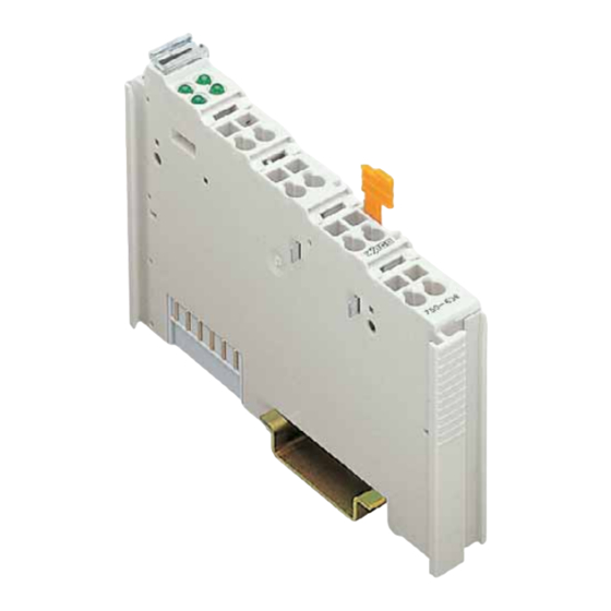
- Page 1 Fieldbus Independent I/O Modules Module Bus Extension Coupler Module 750-628 Manual Version 1.0.1...
- Page 2 • General Copyright 2008 by WAGO Kontakttechnik GmbH & Co. KG All rights reserved. WAGO Kontakttechnik GmbH & Co. KG Hansastraße 27 D-32423 Minden Phone: +49 (0) 571/8 87 – 0 Fax: +49 (0) 571/8 87 – 1 69 E-Mail: info@wago.com...
-
Page 3: Table Of Contents
Special conditions for safe use (ATEX Certificate TÜV 07 ATEX 554086 X) ..................25 3.2.3 Special conditions for safe use (IEC-Ex Certificate TUN 09.0001 X)27 3.2.4 Special conditions for safe use (ATEX Certificate DEKRA 11ATEX0203 X) ................29 3.2.5 ANSI/ISA 12.12.01 ................30 WAGO-I/O-SYSTEM 750 I/O Modules... -
Page 4: Important Notes
Co. KG, Minden, Germany. Non-observance will involve the right to assert damage claims. WAGO Kontakttechnik GmbH & Co. KG reserves the right to provide for any alterations or modifications that serve to increase the efficiency of technical progress. WAGO Kontakttechnik GmbH & Co. KG owns all rights arising from the granting of patents or from the legal protection of utility patents. -
Page 5: Use Of The 750 Series In Compliance With Underlying Provisions
Legal Bases All responsible persons have to familiarize themselves with the underlying legal standards to be applied. WAGO Kontakttechnik GmbH & Co. KG does not assume any liability whatsoever resulting from improper handling and damage incurred to both WAGO´s own and third-party products by disregarding detailed information in this Manual. -
Page 6: Standards And Guidelines For Operating The 750 Series
(emissions of interference) in compliance with EN 61000-6-3. You will find the detailed information in section "WAGO-I/O-SYSTEM 750" "System Description" "Technical Data". Please observe the safety precautions against electrostatic discharge in accordance with DIN EN 61340-5-1/-3. -
Page 7: Symbols
Observe the precautionary measure for handling components at risk of electrostatic discharge. Note Make important notes that are to be complied with so that a trouble-free and efficient device operation can be guaranteed. Additional Information References to additional literature, manuals, data sheets and internet pages. WAGO-I/O-SYSTEM 750 I/O Modules... -
Page 8: Safety Information
Danger The WAGO-I/O-SYSTEM 750 and its components are an open system. It must only be assembled in housings, cabinets or in electrical operation rooms. Access is only permitted via a key or tool to authorized qualified personnel. -
Page 9: Font Conventions
Only for use in LAN, not for connection to telecommunication circuits. 1.5 Font Conventions Names of paths and data files are marked in italic-type. italic e.g.: C:\Programs\WAGO-IO-CHECK Menu items are marked in italic-type, bold letters. italic e.g.: Save A backslash between two names characterizes the selection of a menu point from a menu. -
Page 10: Scope
1.7 Scope This manual describes the Digital Input Module 750-628 Module Bus Extension Coupler Module of the modular WAGO-I/O-SYSTEM 750. Handling, assembly and start-up are described in the manual of the Fieldbus Coupler. Therefore this documentation is valid only in the connection with the appropriate manual. -
Page 11: O Modules
750-627 of the next assembly is done using a cable with an RJ-45 connector. The I/O module assembly is completed by a standard end module 750-600. Locate the structure of a fieldbus node with internal data bus extension module in section 2.1.1.6 „Module Bus Structure”. WAGO-I/O-SYSTEM 750 I/O Modules... - Page 12 The maximum current that is permitted to flow through the power jumper contacts is 10 A. When configuring the system, the total current should not be exceeded. If this occurs, an additional supply module must be used. WAGO-I/O-SYSTEM 750 I/O Modules...
-
Page 13: Display Elements
2.1.1.4 Operating Elements Designation State Function Matching resistor switched off, coupler module is not the last coupler module Matching resistor Matching resistor switched on, coupler module is the last coupler Abb. 2.1.1-4: Operating module Elements g062803x WAGO-I/O-SYSTEM 750 I/O Modules... -
Page 14: Technical Data
Conformity Marking More Information Detailed references to the approvals are listed in the document "Overview Approvals WAGO-I/O-SYSTEM 750", which you can find on the CD ROM ELECTRONICC Tools and Docs (Item-No.: 0888-0412) or at http:/www.wago.com under Documentation WAGO-I/O-SYSTEM 750 ... -
Page 15: Module Bus Structure
Using a hardware/software version < XXXX0103..., up to 40 I/O modules can be connected to an internal data bus extension coupler module 750-628. Using a hardware/software version >= XXXX0103..., the maximum number of I/O modules that can be connected depends on the field bus coupler/controller used. WAGO-I/O-SYSTEM 750 I/O Modules... - Page 16 750-347 CANopen ECO Coupler 750-348 CANopen ECO Coupler 750-806 Contr. DeviceNet 750-819 Contr. LONWORS 750-833 Contr. PROFIBUS DP 12 MBd/DPV1 750-837 Contr. CANopen 750-838 Contr. CANopen Sub D 750-841 Contr. Ethernet TCP/IP 10/100MBit 750-842 Contr. Ethernet WAGO-I/O-SYSTEM 750 I/O Modules...
-
Page 17: Installation Notes
In order to guarantee safe operating conditions while using the internal data bus extension modules 750-627/-628, the bus couplers must have the internal parameters set accordingly. Please order the WAGO extension setting tool 759-314 and use it to inform the bus couplers/controllers... -
Page 18: Use In Hazardous Environments
18 • Use in Hazardous Environments 3 Use in Hazardous Environments The WAGO-I/O-SYSTEM 750 (electrical equipment) is designed for use in Zone 2 hazardous areas. The following sections include both the general identification of components (devices) and the installation regulations to be observed. The individual subsections of the "Installation Regulations"... -
Page 19: Marking Configuration Examples
Approval body and/or number of the examination IECEx PTB 07.0064X certificate I M2 / II 3 GD Explosion protection group and Unit category Ex nA Type of ignition and extended identification Explosion protection group Temperature class WAGO-I/O-SYSTEM 750 I/O Modules... - Page 20 Figure 3: Side marking example for Ex i and IEC Ex i approved I/O modules according to CENELEC and IEC Figure 4: Text detail – Marking example for Ex i and IEC Ex i approved I/O modules according to CENELEC and IEC WAGO-I/O-SYSTEM 750 I/O Modules...
- Page 21 Device category: Zone 2 device (Zone 0 subunit) Explosion protection mark Type of protection: Non-sparking operating equipment [ia] Category of type of protection intrinsic safety: Even safe when two errors occur Explosion Group Temperature class: Max. surface temperature 135°C WAGO-I/O-SYSTEM 750 I/O Modules...
-
Page 22: Marking For America According To Nec 500
Table 3: Description of marking example for I/O modules according to NEC 500 Printing on Text Description CL 1 Explosion protection group (condition of use category) DIV 2 Area of application (zone) Grp. ABCD Explosion group (gas group) Optemp code T4 Temperature class WAGO-I/O-SYSTEM 750 I/O Modules... -
Page 23: Installation Regulations
NFPA 70 National Electrical Code Art. 500 Hazardous Locations ANSI/ISA-RP 12.6-1987 Recommended Practice C22.1 Canadian Electrical Code Notice the following points When using the WAGO-I/O SYSTEM 750 (electrical operation) with Ex approval, the following points are mandatory: WAGO-I/O-SYSTEM 750 I/O Modules... -
Page 24: Special Conditions For Safe Operation Of The Atex And Iec Ex (Acc. Demko 08 Atex 142851X And Iecex Ptb 07.0064)
3.2.1 Special Conditions for Safe Operation of the ATEX and IEC Ex (acc. DEMKO 08 ATEX 142851X and IECEx PTB 07.0064) The fieldbus-independent I/O modules of the WAGO-I/O-SYSTEM 750-.../...-... must be installed in an environment with degree of pollution 2 or better. In the final... -
Page 25: Special Conditions For Safe Use (Atex Certificate Tüv 07 Atex 554086 X)
554086 X) For use as Gc- or Dc-apparatus (in zone 2 or 22) the field bus independent I/O modules WAGO-I/O-SYSTEM 750-*** shall be erected in an enclosure that fulfils the requirements of the applicable standards (see the marking) EN 60079-0, EN 60079-11, EN 60079-15, EN 61241-0 and EN 61241-1. For use as... - Page 26 If the module is energized do not remove or replace the fuse. Do not separate when energized! Do not separate the module when energized! Separate only in a non-hazardous area! Separate the module only in a non-hazardous area! WAGO-I/O-SYSTEM 750 I/O Modules...
-
Page 27: Special Conditions For Safe Use (Iec-Ex Certificate Tun 09.0001
3.2.3 Special conditions for safe use (IEC-Ex Certificate TUN 09.0001 For use as Dc- or Gc-apparatus (in zone 2 or 22) the fieldbus independent I/O modules WAGO-I/O-SYSTEM 750-*** shall be erected in an enclosure that fulfils the requirements of the applicable standards (see the marking) IEC 60079-0, IEC 60079-11, IEC 60079-15, IEC 61241-0 and IEC 61241-1. - Page 28 If the module is energized do not remove or replace the fuse. Do not separate when energized! Do not separate the module when energized! Separate only in a non-hazardous area! Separate the module only in a non-hazardous area! WAGO-I/O-SYSTEM 750 I/O Modules...
-
Page 29: Special Conditions For Safe Use (Atex Certificate Dekra 11Atex0203 X)
Address selectors and ID switches may only be adjusted when the system supply is switched off, or when the location is known to be non-hazardous. The ambient temperature range is: 0°C ≤ T ≤ +55°C. WAGO-I/O-SYSTEM 750 I/O Modules... -
Page 30: Ansi/Isa 12.12.01
Devices containing fuses must not be fitted into circuits subject to over loads! Devices containing fuses must not be fitted into circuits subject to over loads, e.g. motor circuits! WAGO-I/O-SYSTEM 750 I/O Modules... - Page 31 Proof of certification is available on request. Also take note of the information given on the module technical information sheet. The Instruction Manual, containing these special conditions for safe use, must be readily available to the user. WAGO-I/O-SYSTEM 750 I/O Modules...
- Page 32 WAGO Kontakttechnik GmbH & Co. KG Postfach 2880 • D-32385 Minden Hansastraße 27 • D-32423 Minden Phone: 05 71/8 87 – 0 Fax: 05 71/8 87 – 1 69 E-Mail: info@wago.com Internet: http://www.wago.com...
Need help?
Do you have a question about the WAGO-I/O-SYSTEM 750 Series and is the answer not in the manual?
Questions and answers