
Related Manuals for WAGO 750-651


Summary of Contents for WAGO 750-651
- Page 1 Fieldbus Independent I/O Modules TTY-Interface 20mA Current Loop 750-651 (/xxx-xxx) Manual Version 1.0.2...
- Page 2 • General Copyright 2006 by WAGO Kontakttechnik GmbH & Co. KG All rights reserved. WAGO Kontakttechnik GmbH & Co. KG Hansastraße 27 D-32423 Minden Phone: +49 (0) 571/8 87 – 0 Fax: +49 (0) 571/8 87 – 1 69 E-Mail: info@wago.com...
-
Page 3: Table Of Contents
Symbols ....................5 Number Notation..................5 Safety Notes ..................... 6 Scope ......................6 2 I/O Modules ....................7 Special Modules ..................7 2.1.1 750-651 (/xxx-xxx) [TTY-Interface 20mA Current Loop] ....7 2.1.1.1 View....................7 2.1.1.2 Variations..................7 2.1.1.3 Description..................8 2.1.1.4... -
Page 4: Important Comments
WAGO Kontakttechnik GmbH & Co. KG declines all liability resulting from improper action and damage to WAGO products and third party products due to non-observance of the information contained in this manual. -
Page 5: Symbols
Routines or advice for efficient use of the device and software optimization. More information References on additional literature, manuals, data sheets and INTERNET pages 1.3 Number Notation Number Code Example Note Decimal normal notation Hexadecimal 0x64 C notation Binary '100' Within ', '0110.0100' Nibble separated with dots WAGO-I/O-SYSTEM 750 I/O Modules... -
Page 6: Safety Notes
Do not use any contact spray. The spray may impair the functioning of the contact area. The WAGO-I/O-SYSTEM 750 and its components are an open system. It must only be assembled in housings, cabinets or in electrical operation rooms. Access must only be given via a key or tool to authorized qualified personnel. -
Page 7: O Modules
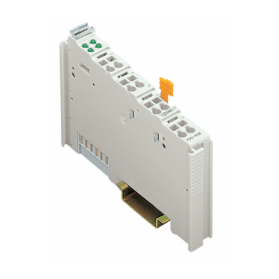
750-651 (/xxx-xxx) [TTY-Interface 20mA Current Loop] • 7 View 2 I/O Modules 2.1 Special Modules 2.1.1 750-651 (/xxx-xxx) [TTY-Interface 20mA Current Loop] 2.1.1.1 View 13 14 Function Data contacts Receiver Transmitter 750-651 Fig. 2.1.1-1: TTY-Interface 750-651 g065100e 2.1.1.2 Variations Item-No. -
Page 8: Description
This module has no power contacts. For field supply to downstream I/O modules, a supply module will be needed. The TTY-Interface module 750-651 and its variations can be used with all couplers/controllers of the WAGO-I/O-SYSTEM 750 (except for the economy types 750-320, -323, -324 and -327). -
Page 9: Display Elements
750-651 (/xxx-xxx) [TTY-Interface 20mA Current Loop] • 9 Display Elements 2.1.1.4 Display Elements Channel State Function Function No operational readiness or the green internal data bus communication is interrupted Operational readiness and trouble- free internal data bus communication Loop current ≤ 2 mA( SPACE) Fig. -
Page 10: Technical Data
10 • 750-651 (/xxx-xxx) [TTY-Interface 20mA Current Loop] Technical Data 2.1.1.6 Technical Data Module Specific Data Transmission channel 1 TxD / 1 RxD, full duplex Baud rate 1200 ... 19200 baud Bit transmission MARK: I ≥ 12 mA, SPACE: I ≤ 2 mA Load impedance <... -
Page 11: Functional Description
System Description 2.1.1.7 Functional description The interface module is designed to operate with all WAGO I/O fieldbus couplers. The TTY interface module allows the connection of TTY-Interface devices to the WAGO I/O SYSTEM. The TTY Interface module can provide gateways within the fieldbus protocol. This allows serial equipment such as printers, barcode readers, and links to local operator interfaces to communicate directly by the fieldbus protocol with the PLC or PC Master. - Page 12 12 • 750-651 (/xxx-xxx) [TTY-Interface 20mA Current Loop] Functional description Current source Current source Receiver with 20 mA 20 mA 13 14 current source 13 14 13 14 20 mA Receiver Receiver Current source Transmitter with 20 mA current source...
-
Page 13: Process Image
2.1.1.8 Process Image Using the module 750-651, a 6 byte input and output process image can be transferred to the fieldbus coupler / controller via one logical channel. The transfer of the data to be transmitted and the received data is made via 5 output and 5 input bytes (D0 ... -
Page 14: Datatransfer
14 • 750-651 (/xxx-xxx) [TTY-Interface 20mA Current Loop] Datatransfer Status byte Bit 7 Bit 6 Bit 5 Bit 4 Bit 3 Bit 2 Bit 1 Bit 0 IL 2 IL 1 IL 0 BUF_F Transmit acknowledge Receive request Initialization acknowledge... -
Page 15: Example
750-651 (/xxx-xxx) [TTY-Interface 20mA Current Loop] • 15 Datatransfer The transmitting and receiving of data can be done simultaneously. The initialization request has priority and will stop transmitting and receiving of data immediately. Attention Resetting the initialization bit can be performed with the following message. - Page 16 16 • 750-651 (/xxx-xxx) [TTY-Interface 20mA Current Loop] Datatransfer As soon as TR=TA, the rest of the data can be sent. Input byte 0 Statusbyte Input byte 2 Input byte 1 '0XXX.XXX0' The data is still being transferred. '0XXX.XXX1' Data transfer completed.
- Page 17 750-651 (/xxx-xxx) [TTY-Interface 20mA Current Loop] • 17 Datatransfer After the 3 characters have been processed, RA is inverted. Output byte 0 Control byte Output byte 2 Output byte 1 '0XXX.001X' If RA≠RR, the receiving of additional characters will continue.
- Page 18 WAGO Kontakttechnik GmbH & Co. KG Postfach 2880 • D-32385 Minden Hansastraße 27 • D-32423 Minden Phone: 05 71/8 87 – 0 Fax: 05 71/8 87 – 1 69 E-Mail: info@wago.com Internet: http://www.wago.com...
Need help?
Do you have a question about the 750-651 and is the answer not in the manual?
Questions and answers