Table of Contents
Advertisement
Quick Links
Advertisement
Table of Contents

Related Manuals for WAGO 750-640


Summary of Contents for WAGO 750-640
- Page 1 Fieldbus Independent I/O Modules RTC Module 750-640 Manual Version 1.0.2...
- Page 2 • General Copyright 2006 by WAGO Kontakttechnik GmbH & Co. KG All rights reserved. WAGO Kontakttechnik GmbH & Co. KG Hansastraße 27 D-32423 Minden Phone: +49 (0) 571/8 87 – 0 Fax: +49 (0) 571/8 87 – 1 69 E-Mail: info@wago.com...
-
Page 3: Table Of Contents
Symbols ....................6 Number Notation..................6 Safety Notes ..................... 7 Scope ......................7 2 I/O Modules ....................8 Special Modules ..................8 2.1.1 750-640 [RTC Module] ............... 8 2.1.1.1 View....................8 2.1.1.2 Description..................8 2.1.1.3 Display Elements ................9 2.1.1.4 Schematic Diagram............... - Page 4 3.1.4.25 SET_OPH_INC (auto incremental), 0x33 ........57 3.1.4.26 GET_SERVICE_FLAGS, 0x34............ 58 3.1.4.27 GET_CNF, 0x38 ................59 3.1.4.28 GET_CNF_INC (auto incremental), 0x39........60 3.1.4.29 SET_CNF, 0x3A................61 3.1.4.30 SET_CNF_INC (auto incremental), 0x3B........62 3.1.4.31 GET_DIAG, 0xFF ................ 63 WAGO-I/O-SYSTEM 750 I/O-Modules...
-
Page 5: Important Comments
WAGO Kontakttechnik GmbH & Co. KG declines all liability resulting from improper action and damage to WAGO products and third party products due to non-observance of the information contained in this manual. -
Page 6: Symbols
Routines or advice for efficient use of the device and software optimization. More information References on additional literature, manuals, data sheets and INTERNET pages 1.3 Number Notation Number Code Example Note Decimal normal notation Hexadecimal 0x64 C notation Binary '100' Within ', '0110.0100' Nibble separated with dots WAGO-I/O-SYSTEM 750 I/O-Modules... -
Page 7: Safety Notes
Do not use any contact spray. The spray may impair the functioning of the contact area. The WAGO-I/O-SYSTEM 750 and its components are an open system. It must only be assembled in housings, cabinets or in electrical operation rooms. Access must only be given via a key or tool to authorized qualified personnel. -
Page 8: O Modules
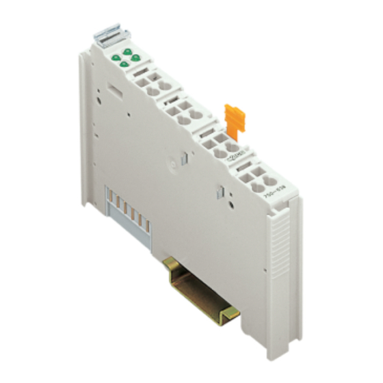
2.1.1.2 Description The RTC module 750-640 provides the higher-level control system with the actual time. The time continues to run in the event of a power failure. Once the module is switched on, about one hour is required for the integrated backup capacitor to be fully charged. -
Page 9: Display Elements
However, if such a case should occur, another supply module must be added. The RTC module 750-640 can be used with all couplers / controllers of the WAGO-I/O-SYSTEM 750 (except for the economy types 750-320, -323, -324 and –327). -
Page 10: Schematic Diagram
10 • 750-640 [RTC Module] Schematic Diagram 2.1.1.4 Schematic Diagram V_Ant -out V_Ant +out 24 V out V_Ant +in 24 V in V_Ant -in Ground Shield Clock 750-640 Fig. 2.1.1-3: Schematic Diagram g064001e WAGO-I/O-SYSTEM 750 I/O-Modules... -
Page 11: Technical Data
750-640 [RTC Module] • 11 Technical Data 2.1.1.5 Technical Data Module Specific Data Current consumption < 20 mA typ. (internal) Voltage via power jumper DC 24 V (-15%...+20%) contacts Clock Accuracy (+25°C) < 1min/month Accuracy (+10...+40°C) < 2min/month Accuracy (-25...+85°C) <... -
Page 12: Functional Description
750-640 [RTC Module] Functional Description More Information Detailed references to the approvals are listed in the document "Overview Approvals WAGO-I/O-SYSTEM 750", which you can find on the CD ROM ELECTRONICC Tools and Docs (Item-No.: 0888-0412) or in the internet under: www.wago.com... -
Page 13: Configuration Data
750-640 [RTC Module] • 13 Functional Description data continuously. Using the SET_DT function, the date and time can be set manually. 2.1.1.6.2 Configuration Data The configuration data of the RTC module can be accessed using the GET_CNF, GET_CNF_INC, SET_CNF and SET_CNF_INC functions. The address offset of the relevant entry must be previously set using the SET_ADDR function. -
Page 14: Example
14 • 750-640 [RTC Module] Functional Description A switching point is defined using the following entries: Offset Meaning Format Length Comment First-time appearance DATE_AND_TIME 32 bit Last appearance DATE_AND_TIME 32 bit 0 = not used Time between two DATE_AND_TIME 32 bit... -
Page 15: Auto
750-640 [RTC Module] • 15 Functional Description Setting the timers is done as follows: Timer Start Stop Interval Days 01.01.1970 Channel 1 Mo-Fr 06:00:00 01.01.1970 Channel 1 Every 18:00:00 26.05.2003 13.06.2003 Channel 1 Every 06:00:01 06:00:01 01.01.1970 Channel 4 Every... -
Page 16: Antenna
16 • 750-640 [RTC Module] Functional Description 2.1.1.6.2.7 Antenna This is how to select the decoder scheme for time signal reception. Byte Function 0 ... 1 0: No time signal reception 1: DCF77 Decoder activated 2: WWVB Decoder activated DCF77 Polarity reversed... -
Page 17: Hours Run And Maintenance Interval
2.1.1.7 Process Image Using the RTC module 750-640, a 6-byte input and output process image maximum can be transferred to the fieldbus coupler/controller via one logical channel. The data received by the transmitter is stored in 4 input and output bytes (D0 ... -
Page 18: Structure Of The Input Data And Output Data
18 • 750-640 [RTC Module] Process Image The control byte includes the following bits: Control Byte Bit 7 Bit 6 Bit 5 Bit 4 Bit 3 Bit 2 Bit 1 Bit 0 Transmit Request, request to send (toggle flag) reserved (constant must be set to zero) -
Page 19: Access To Module Data
750-640 [RTC Module] • 19 Process Image Function Response Byte Opcode (mirrored) Response parameter byte 0 Response parameter byte 1 Response parameter byte 2 Response parameter byte 3 reserved (value is always 0 and is not evaluated) Transmit- A function call is receipted with a changing. -
Page 20: Rtc Module Functions
20 • 750-640 [RTC Module] RTC Module Functions 2.1.1.8 RTC Module Functions 2.1.1.8.1 Function Overview Function Description Site 0x00 IDLE No function call Date and Time Functions 0x01 GET_TOD100 Getting time in 100µs since 00:00 Getting time in 100µs since 00:00,... - Page 21 750-640 [RTC Module] • 21 RTC Module Functions Function Description Site Address Functions Getting the address offset for configuration 0x20 GET_ADDR data or hours-run meter Setting address offset for configuration data 0x21 SET_ADDR or service data Service Data Functions 0x30...
-
Page 22: Example Of Function Call
22 • 750-640 [RTC Module] RTC Module Functions 2.1.1.8.2 Example of Function Call 2.1.1.8.2.1 Data Reading • Writing the data to be transmitted in output byte D0 ... D3 • Specifying the function with ID or reversing TR • Transfer to the transmit buffer is complete when TA == TR... -
Page 23: Writing Data In Safe Configuration Area
750-640 [RTC Module] • 23 RTC Module Functions Example: Getting address offset (GET_ADDR, ID 0x20) Original values: Output data Value 0x00 0x00 0x00 0x00 0x00 0x00 Input Data 0x00 0x00 0x00 0x00 0x00 0x00 Value Writing ID (GET_ADDR, ID 0x20) or reversing TR (Bit 0 in control byte C),... - Page 24 24 • 750-640 [RTC Module] RTC Module Functions Setting address offset of password: Output data Value 0x00 0x00 0x10 0x03 0x00 0x00 Input Data Value 0x00 0x00 0x00 0x00 0x00 0x00 Transmitting address offset of password (SET_ADDR, ID = 0x21):...
- Page 25 750-640 [RTC Module] • 25 RTC Module Functions Setting time zone: Output data Value 0x01 0x21 0x10 0x0E 0x00 0x00 Input Data Value 0x01 0x21 0x00 0x00 0x00 0x00 Transmitting time zone (SET_CNF, ID = 0x3A): Output data Value 0x01...
-
Page 26: Connection Examples
26 • 750-640 [RTC Module] Connection Examples 2.1.1.9 Connection Examples 2.1.1.9.1 Antenna Supply with 24 V +24 V V_ANT+ out V_ANT- out Antenna Ub = 24 V Signal 24 V out V_ANT+ in V_ANT- in Clock Shield Fig. 2.1.1-5: Antenna Supply with 24 V g064003e 2.1.1.9.2... -
Page 27: Attachment
Setting switching states of the switching 0x11 SET_CHANNEL channels Clearing switching states of the switching 0x12 CLEAR_CHANNEL channels Getting automatic states of the switching 0x13 GET_AUTO channels Setting automatic states of the switching 0x14 SET_AUTO channels WAGO-I/O-SYSTEM 750 I/O-Modules... - Page 28 Getting service indication of the hours-run 0x34 GET_SERVICE_FLAGS meter Configuration Data Functions 0x38 GET_CNF Getting configuration data Getting configuration data, (auto 0x39 GET_CNF_INC incremental) 0x3A SET_CNF Setting configuration data Setting configuration data, (auto 0x3B SET_CNF_INC incremental) 0xFF GET_DIAG Getting self-test diagnostic WAGO-I/O-SYSTEM 750 I/O-Modules...
-
Page 29: Function Overview Sorted By Id
Getting the address offset for configuration 0x20 GET_ADDR data or hours-run meter Setting address offset for configuration data 0x21 SET_ADDR or service data 0x30 GET_OPH Getting service data 0x31 GET_OPH_INC Getting service data, (auto incremental) 0x32 SET_OPH Setting service data WAGO-I/O-SYSTEM 750 I/O-Modules... - Page 30 Getting service indication of the hours-run 0x34 GET_SERVICE_FLAGS meter 0x38 GET_CNF Getting configuration data Getting configuration data, (auto 0x39 GET_CNF_INC incremental) 0x3A SET_CNF Setting configuration data Setting configuration data, (auto 0x3B SET_CNF_INC incremental) 0xFF GET_DIAG Getting self-test diagnostic WAGO-I/O-SYSTEM 750 I/O-Modules...
-
Page 31: Function Overview Sorted By Function
GET_TOD100 Getting time in 100µs since 00:00 Getting time in seconds since 1.1.1970 0x04 GET_UTC 00:00 (UTC) 0x07 GET_WEEKDAY Getting weekday 0x00 IDLE No function call Setting address offset for configuration data 0x21 SET_ADDR or service data WAGO-I/O-SYSTEM 750 I/O-Modules... - Page 32 Setting switching states of the switching 0x11 SET_CHANNEL channels 0x3A SET_CNF Setting configuration data Setting configuration data, (auto 0x3B SET_CNF_INC incremental) Setting time in seconds since 1.1.1970 0x0F SET_DT 00:00 0x32 SET_OPH Setting service data 0x33 SET_OPH_INC Setting service data, (auto incremental) WAGO-I/O-SYSTEM 750 I/O-Modules...
-
Page 33: Function Reference
Function Response Byte 0x00 0xXX 0xXX 0xXX 0xXX 0xXX any return value Example: The function can be called, for example, to reverse the toggle flag without effects or to stop the process of consecutive functions. WAGO-I/O-SYSTEM 750 I/O-Modules... -
Page 34: Get_Tod100, 0X01
0xXX 0xXX any return value Function Response Byte 0x01 Time (low byte) Time (high byte) Example: 08:45:35 ≙ ((8*60+45)*60+35)*10000 = 315350000 ≙ 0x12CBDBF0 Input data: D0 = 0xF0, D1 = 0xDB, D2 = 0xCB, D3 = 0x12 WAGO-I/O-SYSTEM 750 I/O-Modules... -
Page 35: Get_Current_Tod100, 0X09
0xXX 0xXX any return value Function Response Byte 0x09 Time (low byte) Time (high byte) Example: 08:45:35 ≙ ((8*60+45)*60+35)*10000 = 315350000 ≙ 0x12CBDBF0 Input data: D0 = 0xF0, D1 = 0xDB, D2 = 0xCB, D3 = 0x12 WAGO-I/O-SYSTEM 750 I/O-Modules... -
Page 36: Get_Tod, 0X02
0xXX 0xXX any return value Function Response Byte 0x02 Time (low byte) Time (high byte) Example: 08:45:35 ≙ ((8*60+45)*60+35)*1000 = 31535000 ≙ 0x01E12F98 Input data: D0 = 0x98, D1 = 0x2F, D2 = 0xE1, D3 = 0x01 WAGO-I/O-SYSTEM 750 I/O-Modules... -
Page 37: Get_Current_Tod, 0X0A
0xXX 0xXX any return value Function Response Byte 0x0A Time (low byte) Time (high byte) Example: 08:45:35 ≙ ((8*60+45)*60+35)*1000 = 31535000 ≙ 0x01E12F98 Input data: D0 = 0x98, D1 = 0x2F, D2 = 0xE1, D3 = 0x01 WAGO-I/O-SYSTEM 750 I/O-Modules... -
Page 38: Get_Dt, 0X03
Function Response Byte 0x03 Date and time (low byte) Date and time (high byte) Example: 27.03.2003 16:06:23 ≙ 1048781183 ≙ 0x3E83217F Input data: D0 = 0x7F, D1 = 0x21, D2 = 0x83, D3 = 0x3E WAGO-I/O-SYSTEM 750 I/O-Modules... -
Page 39: Get_Current_Dt, 0X0B
Function Response Byte 0x0B Date and time (low byte) Date and time (high byte) Example: 27.03.2003 16:06:23 ≙ 1048781183 ≙ 0x3E83217F Input data: D0 = 0x7F, D1 = 0x21, D2 = 0x83, D3 = 0x3E WAGO-I/O-SYSTEM 750 I/O-Modules... -
Page 40: Get_Utc, 0X04
Date and time (low byte) Date and time (high byte) Example: Summer time in Germany (MESZ) 27.03.2003 16:06:23 ≙ 1048781183 – 2*3600 = 1048773983 ≙ 0x3E83055F Input data: D0 = 0x5F, D1 = 0x05, D2 = 0x83, D3 = 0x3E WAGO-I/O-SYSTEM 750 I/O-Modules... -
Page 41: Get_Current_Utc, 0X0C
Date and time (low byte) Date and time (high byte) Example: Summer time in Germany (MESZ) 27.03.2003 16:06:23 ≙ 1048781183 – 2*3600 = 1048773983 ≙ 0x3E83055F Input data: D0 = 0x5F, D1 = 0x05, D2 = 0x83, D3 = 0x3E WAGO-I/O-SYSTEM 750 I/O-Modules... -
Page 42: Get_Date, 0X05
Function Response Byte 0x05 Date and time (low byte) Date and time (high byte) Example: 27.03.2003 00:00:00 ≙ 1048723200 ≙ 0x3E823F00 27.03.2003 16:06:23 → Input data: D0 = 0x00, D1 = 0x3F, D2 = 0x82, D3 = 0x3E WAGO-I/O-SYSTEM 750 I/O-Modules... -
Page 43: Get_Current_Date, 0X0D
Function Response Byte 0x0D Date and time (low byte) Date and time (high byte) Example: 27.03.2003 00:00:00 ≙ 1048723200 ≙ 0x3E823F00 27.03.2003 16:06:23 → Input data: D0 = 0x00, D1 = 0x3F, D2 = 0x82, D3 = 0x3E WAGO-I/O-SYSTEM 750 I/O-Modules... -
Page 44: Get_Ms, 0X06
0xXX any return value Function Response Byte 0x06 Milliseconds (low byte) Milliseconds (high byte) 0x00 0x00 Example: 462 ≙ 0x000001CE 27.03.2003 16:06:23.462 → Input data: D0 = 0xCE, D1 = 0x01, D2 = 0x00, D3 = 0x00 WAGO-I/O-SYSTEM 750 I/O-Modules... -
Page 45: Get_Weekday, 0X07
0xXX 0xXX 0xXX 0xXX 0xXX any return value Function Response Byte 0x07 Day of the week 0x00 0x00 0x00 Example: Wednesday ≙ 2 Input data: D0 = 0x02, D1 = 0x00, D2 = 0x00, D3 = 0x00 WAGO-I/O-SYSTEM 750 I/O-Modules... -
Page 46: Set_Dt, 0X0F
Date and time (low byte) Date and time (high byte) Function Response Byte 0x0F 0x00 0x00 0x00 0x00 Example: 27.03.2003 16:06:23 ≙ 1048781183 ≙ 0x3E83217F Output data: D0 = 0x7F, D1 = 0x21, D2 = 0x83, D3 = 0x3E WAGO-I/O-SYSTEM 750 I/O-Modules... -
Page 47: Get_Channel, 0X10
Switching channel 0 – switching channel 31 Example: The switching channels 1, 17, 19, 20, 21, 22, 23 are on, all other switching channels are off ≙ (0x00FA0002): Input data: D0 = 0x02, D1 = 0x00, D2 = 0xFA, D3 = 0x00 WAGO-I/O-SYSTEM 750 I/O-Modules... -
Page 48: Set_Channel, 0X11
Switching channel 0 – switching channel 31 Function Response Byte 0x11 0x00 0x00 0x00 0x00 Example: Switching channels 8, 10, 12 and 14 must be set ≙ (0x00005500): Output data: D0 = 0x00, D1 = 0x55, D2 = 0x00, D3 = 0x00 WAGO-I/O-SYSTEM 750 I/O-Modules... -
Page 49: Clear_Channel, 0X12
Switching channel 0 – switching channel 31 Function Response Byte 0x12 0x00 0x00 0x00 0x00 Example: Switching channels 17, 19, 21 and 23 must be set ≙ (0x00AA0000): Output data: D0 = 0x00, D1 = 0x00, D2 = 0xAA, D3 = 0x00 WAGO-I/O-SYSTEM 750 I/O-Modules... -
Page 50: Get_Auto, 0X13
Switching channel 0 – switching channel 31 Example: The switching channels 2, 4 and 6 are in manual mode, all other switching channels are in automatic mode ≙ (0x00000054): Input data: D0 = 0x54, D1 = 0x00, D2 = 0x00, D3 = 0x00 WAGO-I/O-SYSTEM 750 I/O-Modules... -
Page 51: Set_Auto, 0X14
0x14 0x00 0x00 0x00 0x00 Example: For the switching channels 9, 11 and 13 the automatic mode must be switched off ≙ (0x00002A00): Output data: D0 = 0x00, D1 = 0x2A, D2 = 0x00, D3 = 0x00 WAGO-I/O-SYSTEM 750 I/O-Modules... -
Page 52: Get_Addr, 0X20
0xXX any return value Function Response Byte 0x20 Address offset (low byte) Address offset (high byte) Example: Address offset contains the value 0x12345678: Input data: D0 = 0x78, D1 = 0x56, D2 = 0x34, D3 = 0x12 WAGO-I/O-SYSTEM 750 I/O-Modules... -
Page 53: Set_Addr, 0X21
Byte 0x21 Address offset (low byte) Address offset (high byte) Function Response Byte 0x21 0x00 0x00 0x00 0x00 Example: Reading address offset 0x12345678: Output data: D0 = 0x78, D1 = 0x56, D2 = 0x34, D3 = 0x12 WAGO-I/O-SYSTEM 750 I/O-Modules... -
Page 54: Get_Oph, 0X30
SET_ADDR function. Function Request Byte 0x30 0xXX 0xXX 0xXX 0xXX 0xXX any return value Function Response Byte 0x30 (Low byte) (High byte) WAGO-I/O-SYSTEM 750 I/O-Modules... -
Page 55: Get_Oph_Inc (Auto Incremental), 0X31
SET_ADDR function. When a new function call is made, 4 bytes are automatically added to the address offset. Function Request Byte 0x31 0xXX 0xXX 0xXX 0xXX 0xXX any return value Function Response Byte 0x31 (Low byte) (High byte) WAGO-I/O-SYSTEM 750 I/O-Modules... -
Page 56: Set_Oph, 0X32
Before calling this function for the first time, the required address offset must be set for the hours run or maintenance interval of the appropriate meter using the SET_ADDR function. Function Request Byte 0x32 (Low byte) (High byte) Function Response Byte 0x32 0x00 0x00 0x00 0x00 WAGO-I/O-SYSTEM 750 I/O-Modules... -
Page 57: Set_Oph_Inc (Auto Incremental), 0X33
SET_ADDR function. When a new function call is made, 4 bytes are automatically added to the address offset. Function Request Byte 0x33 (Low byte) (High byte) Function Response Byte 0x33 0x00 0x00 0x00 0x00 WAGO-I/O-SYSTEM 750 I/O-Modules... -
Page 58: Get_Service_Flags, 0X34
Maintenance interval switching channel 1, 17, 19, 20, 21, 22, 23 is exceeded ≙ (0x00FA0002): Input data: D0 = 0x02, D1 = 0x00, D2 = 0xFA, D3 = 0x00 Deleting requires that the relevant meters have been set to 0. WAGO-I/O-SYSTEM 750 I/O-Modules... -
Page 59: Get_Cnf, 0X38
Before calling this function for the first time, the required address offset must be set for configuration data of the appropriate meter using the SET_ADDR function. Function Request Byte 0x38 0xXX 0xXX 0xXX 0xXX 0xXX any return value Function Response Byte 0x38 (Low byte) (High byte) WAGO-I/O-SYSTEM 750 I/O-Modules... -
Page 60: Get_Cnf_Inc (Auto Incremental), 0X39
When a new function call is made, 4 bytes are automatically added to the address offset. Function Request Byte 0x39 0xXX 0xXX 0xXX 0xXX 0xXX any return value Function Response Byte 0x39 (Low byte) (High byte) WAGO-I/O-SYSTEM 750 I/O-Modules... -
Page 61: Set_Cnf, 0X3A
Before calling this function for the first time, the required address offset must be set for configuration data of the appropriate meter using the SET_ADDR function. Function Request Byte 0x3A (Low byte) (High byte) Function Response Byte 0x3A 0x00 0x00 0x00 0x00 WAGO-I/O-SYSTEM 750 I/O-Modules... -
Page 62: Set_Cnf_Inc (Auto Incremental), 0X3B
SET_ADDR function. When a new function call is made, 4 bytes are automatically added to the address offset. Function Request Byte 0x3B (Low byte) (High byte) Function Response Byte 0x3B 0x00 0x00 0x00 0x00 WAGO-I/O-SYSTEM 750 I/O-Modules... -
Page 63: Get_Diag, 0Xff
The following table shows the signification of the possible diagnostics information. Diagnostics Information (Input Byte D0) Diagnostics Antenna signal level Buffer voltage too small or clock failed Antenna signal not available or defect Memory is not addressable WAGO-I/O-SYSTEM 750 I/O-Modules... - Page 64 WAGO Kontakttechnik GmbH & Co. KG Postfach 2880 • D-32385 Minden Hansastraße 27 • D-32423 Minden Phone: 05 71/8 87 – 0 Fax: 05 71/8 87 – 1 69 E-Mail: info@wago.com Internet: http://www.wago.com...
Need help?
Do you have a question about the 750-640 and is the answer not in the manual?
Questions and answers