
Related Manuals for WAGO 753-668/000-004


Summary of Contents for WAGO 753-668/000-004
- Page 1 Manual WAGO-I/O-SYSTEM 750 753-668/000-004 4FAI 0/4-20 mA Diff PROFIsafe Fail-safe 4-channel analog input; 0/4...20 mA; Differential inputs; PROFIsafe Version 1.0.0, valid from HW/SW Version 01/01...
- Page 2 We wish to point out that the software and hardware terms as well as the trademarks of companies used and/or mentioned in the present manual are generally protected by trademark or patent. WAGO is a registered trademark of WAGO Verwaltungsgesellschaft mbH. Manual Version 1.0.0, valid from HW/SW Version 01/01...
-
Page 3: Table Of Contents
2.1.3 Use of the 750 Series in Compliance with Underlying Provisions ..............13 2.1.4 Technical Condition of Specified Devices......... 14 System Requirements for the WAGO Parameterization Tool ....15 2.2.1 PC Hardware ................... 15 2.2.2 PC Software ..................15 Safety Advice (Precautions) ..............16 Device Description .................. - Page 4 Table of Contents WAGO-I/O-SYSTEM 750 753-668/000-004 4FAI 0/4-20 mA Diff PROFIsafe 3.6.10.2 Safety Response Time of Analog Inputs for Two-Channel Applications without Discrepancy Monitoring ............... 41 3.6.10.3 Safety Response Time of Analog Inputs for Two-Channel Applications with Discrepancy Monitoring ............... 42 3.6.10.3.1...
- Page 5 WAGO-I/O-SYSTEM 750 Table of Contents 753-668/000-004 4FAI 0/4-20 mA Diff PROFIsafe Measurement Range 4 … 20 mA with 5.9.2.3 Wire Break Detection Disabled ............ 73 5.9.3 RIOforPA Representation ..............73 Measurement Range 0 … 20 mA ..........74 5.9.3.1 Measurement Range 4 … 20 mA ..........74 5.9.3.2...
- Page 6 F I/O Module with PROFIsafe Mode V2.4 or V2.6 ......105 8.4.2 F I/O Module with iPar Server ............106 8.4.3 F I/O Module with iPar Server from WAGO ........106 8.4.4 F I/O Module without iPar Server ........... 107 Diagnostics.................... 108 Error Detection ...................
- Page 7 WAGO-I/O-SYSTEM 750 Table of Contents 753-668/000-004 4FAI 0/4-20 mA Diff PROFIsafe 10.1.3.2 PROFIsafe Address Set Using the Parameterization Tool ............... 134 Use in Hazardous Environments ............135 11.1 Marking Configuration Examples ............136 11.1.1 Marking for Europe According to ATEX and IECEx ......136 11.1.2...
-
Page 8: Notes About This Documentation
This documentation applies to: “4FAI 0/4-20 mA Diff PROFIsafe” (753-668/000-004). This documentation is only applicable from HW/SW Version 01/01. The I/O module 753-668/000-004 shall only be installed and operated according to the instructions in this manual and in the manual for the used fieldbus coupler or controller. -
Page 9: Copyright
Manual by third parties that violate pertinent copyright provisions is prohibited. Reproduction, translation, electronic and phototechnical filing/archiving (e.g., photocopying) as well as any amendments require the written consent of WAGO Kontakttechnik GmbH & Co. KG, Minden, Germany. Non-observance will involve the right to assert damage claims. Manual... -
Page 10: Symbols
Notes about this Documentation WAGO-I/O-SYSTEM 750 753-668/000-004 4FAI 0/4-20 mA Diff PROFIsafe Symbols Personal Injury! Indicates a high-risk, imminently hazardous situation which, if not avoided, will result in death or serious injury. Personal Injury Caused by Electric Current! Indicates a high-risk, imminently hazardous situation which, if not avoided, will result in death or serious injury. - Page 11 WAGO-I/O-SYSTEM 750 Notes about this Documentation 753-668/000-004 4FAI 0/4-20 mA Diff PROFIsafe Additional Information: Refers to additional information which is not an integral part of this documentation (e.g., the Internet). Manual Version 1.0.0, valid from HW/SW Version 01/01...
-
Page 12: Number Notation
Notes about this Documentation WAGO-I/O-SYSTEM 750 753-668/000-004 4FAI 0/4-20 mA Diff PROFIsafe Number Notation Table 1: Number Notation Number Code Example Note Decimal Normal notation Hexadecimal 0x64 C notation Binary '100' In quotation marks, nibble separated '0110.0100' with dots (.) -
Page 13: Important Notes
2.1.1 Subject to Changes WAGO Kontakttechnik GmbH & Co. KG reserves the right to provide for any alterations or modifications. WAGO Kontakttechnik GmbH & Co. KG owns all rights arising from the granting of patents or from the legal protection of utility patents. -
Page 14: Technical Condition Of Specified Devices
These modules contain no parts that can be serviced or repaired by the user. The following actions will result in the exclusion of liability on the part of WAGO Kontakttechnik GmbH & Co. KG: •... -
Page 15: System Requirements For The Wago Parameterization Tool
WAGO-I/O-SYSTEM 750 Important Notes 753-668/000-004 4FAI 0/4-20 mA Diff PROFIsafe System Requirements for the WAGO Parameterization Tool 2.2.1 PC Hardware Table 3: PC Hardware Requirements Component Requirements Memory Min. 1 GB Free hard disk space Min. 500 MB; additional 5.5 GB for the .NET Framework Processor Min. -
Page 16: Safety Advice (Precautions)
Important Notes WAGO-I/O-SYSTEM 750 753-668/000-004 4FAI 0/4-20 mA Diff PROFIsafe Safety Advice (Precautions) For installing and operating purposes of the relevant device to your system the following safety precautions shall be observed: Do not work on devices while energized! All power sources to the device shall be switched off prior to performing any installation, repair or maintenance work. - Page 17 WAGO-I/O-SYSTEM 750 Important Notes 753-668/000-004 4FAI 0/4-20 mA Diff PROFIsafe Observe applicable standards! In a safety-related application, both the control as well as the attached sensors and actuators must meet the the applicable normative safety requirements. Ensure that switches, sensors and actuators comply with current applicable standards before use.
- Page 18 Important Notes WAGO-I/O-SYSTEM 750 753-668/000-004 4FAI 0/4-20 mA Diff PROFIsafe Avoid electrostatic discharge! The devices are equipped with electronic components that may be destroyed by electrostatic discharge when touched. Please observe the safety precautions against electrostatic discharge per IEC 61340-5-1/-3. When handling the devices, please ensure that environmental factors (personnel, work space and packaging) are properly grounded.
-
Page 19: Device Description
Sensors with analog output signal (0 mA … 20 mA and 4 mA … 20 mA) can be connected to the inputs of the F I/O module 753-668/000-004 per IEC 60381-1 (see Section “Connecting Devices” > … > “Connection Examples”): •... - Page 20 Detailed information and examples for supplying F I/O modules is available in the section “Connect Devices” > … > “Power Supply Concept”. The F I/O module 753-668/000-004 (4FAI 0/4-20 mA Diff PROFIsafe) receives the 24 V voltage supply for the field level from an upstream I/O module or from the fieldbus coupler/controller via blade-formed power jumper contacts.
-
Page 21: View
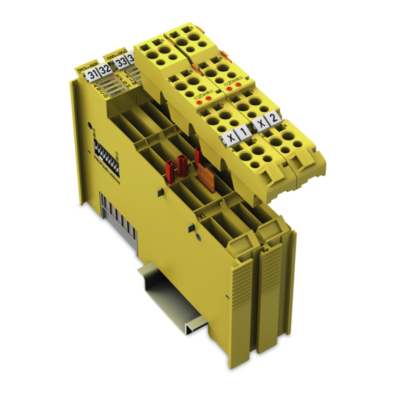
WAGO-I/O-SYSTEM 750 Device Description 753-668/000-004 4FAI 0/4-20 mA Diff PROFIsafe View Figure 1: View Table 5: Legend for Figure “View” Pos. Description Details See Section Marking possibility with Mini- “Device Description” > “Display Status-LEDs Elements” “Device Description” > “Connectors” Data contacts ®... -
Page 22: Connectors
Device Description WAGO-I/O-SYSTEM 750 753-668/000-004 4FAI 0/4-20 mA Diff PROFIsafe Connectors 3.2.1 Data Contacts/Local Bus Communication between the fieldbus coupler/controller and the I/O modules as well as the system supply of the I/O modules is carried out via the local bus. The contacting for the local bus consists of 6 data contacts, which are available as self-cleaning gold spring contacts. -
Page 23: Power Jumper Contacts/Field Supply
The blade contacts are sharp-edged. Handle the I/O module carefully to prevent injury. Do not touch the blade contacts. The I/O module 753-668/000-004 has 2 self-cleaning power jumper contacts that supply and transmit power for the field side. The contacts on the left side of the I/O module are designed as blade contacts and those on the right side as spring contacts. - Page 24 Device Description WAGO-I/O-SYSTEM 750 753-668/000-004 4FAI 0/4-20 mA Diff PROFIsafe Use supply modules for ground (earth)! The I/O module has no power jumper contacts for receiving and transmitting the earth potential. Use a supply module when an earth potential is needed for the subsequent I/O modules.
-
Page 25: Cage Clamp Connectors
WAGO-I/O-SYSTEM 750 Device Description 753-668/000-004 4FAI 0/4-20 mA Diff PROFIsafe ® 3.2.3 CAGE CLAMP Connectors ® Figure 4: CAGE CLAMP Connectors ® Table 7: Legend for Figure “CAGE CLAMP Connectors” Channel Designation Connector Function Supply output, sensor L1− Ground connection, sensor Supply output, sensor L2−... - Page 26 Shield Connection System for Electromagnetic Compatibility! The WAGO Shield Connection System offers a full range of accessories for maintaining electromagnetic compatibility (EMC)! Related information is available at www.wago.com.
-
Page 27: Display Elements
WAGO-I/O-SYSTEM 750 Device Description 753-668/000-004 4FAI 0/4-20 mA Diff PROFIsafe Display Elements Figure 5: Indicators of the Right Half of the Enclosure Table 8: Legend for Figure “Indicators of the Right Half of the Enclosure” Channel Designation Status Function Input AI1: Disabled... -
Page 28: Figure 6: Indicators, Communication / I/O Module Status
Device Description WAGO-I/O-SYSTEM 750 753-668/000-004 4FAI 0/4-20 mA Diff PROFIsafe Figure 6: Indicators, Communication / I/O Module Status Table 9: Legend for Figure “Indicators, Communication / I/O Module Status” Designation Status Function No error Module, channel pair or channel error (see Section “Diagnostics”... -
Page 29: Operating Elements
If the problem occurs several times, it points to a defect in the F I/O module. In this case, return the F I/O module to WAGO Kontakttechnik GmbH & Co. KG for fault analysis. Defective firmware is detected via the corresponding diagnostics (see Section “Diagnostics”). -
Page 30: Schematic Diagrams
Device Description WAGO-I/O-SYSTEM 750 753-668/000-004 4FAI 0/4-20 mA Diff PROFIsafe Schematic Diagrams Figure 8: Schematic Diagram Manual Version 1.0.0, valid from HW/SW Version 01/01... -
Page 31: Technical Data
WAGO-I/O-SYSTEM 750 Device Description 753-668/000-004 4FAI 0/4-20 mA Diff PROFIsafe Technical Data 3.6.1 Device Data Table 10: Technical Data – Device Data Width 24 mm Height (from upper edge of DIN-rail) 64 mm Depth 100 mm Weight 110 g 3.6.2 Power Supply Table 11: Technical Data –... -
Page 32: Communication
Device Description WAGO-I/O-SYSTEM 750 753-668/000-004 4FAI 0/4-20 mA Diff PROFIsafe 3.6.3 Communication Table 12: Technical Data – Communication 750-333 SW 22 or higher Usable fieldbus couplers 750-375 SW 08 or higher 750-377 SW 08 or higher GSD specification Version 5.1... - Page 33 WAGO-I/O-SYSTEM 750 Device Description 753-668/000-004 4FAI 0/4-20 mA Diff PROFIsafe Tolerance values can be exceeded by EMC interference! The tolerance values for the analog inputs specified in the technical data can be exceeded by EMC interference. To reduce measurement value deviations, adjust the settings in the “Smoothing”...
-
Page 34: Table 13: Technical Data - Analog Inputs
Device Description WAGO-I/O-SYSTEM 750 753-668/000-004 4FAI 0/4-20 mA Diff PROFIsafe Table 13: Technical Data – Analog Inputs 4 (single-channel analysis) Number of inputs 2 pairs (two-channel analysis) Connection types 2-, 3- and 4-wire connection 0 … 20 mA Measurement range 4 …... -
Page 35: Filter Characteristics
WAGO-I/O-SYSTEM 750 Device Description 753-668/000-004 4FAI 0/4-20 mA Diff PROFIsafe Safety-related accuracy can be improved! Application-specific averaging can improve safety-related accuracy from ±1.58 % to ±1.25 % for two-channel use. For this purpose, the mean value of the two process values must be formed by the safe PLC. -
Page 36: Safety Parameters
Device Description WAGO-I/O-SYSTEM 750 753-668/000-004 4FAI 0/4-20 mA Diff PROFIsafe 3.6.7 Safety Parameters 3.6.7.1 Two-Channel Safety Application Table 16: Safety Parameters for Two-Channel Safety Application Maximum safety integrity level per IEC 62061 SIL 3 Maximum safety integrity level per IEC 61508... -
Page 37: Single-Channel Safety Application
WAGO-I/O-SYSTEM 750 Device Description 753-668/000-004 4FAI 0/4-20 mA Diff PROFIsafe 3.6.7.2 Single-Channel Safety Application Table 17: Safety Parameters for Single-Channel Safety Application Maximum safety integrity level per IEC 62061 SIL 2 Maximum safety integrity level per IEC 61508 SIL 2 Maximum performance level per EN ISO 13849-1 Cat. -
Page 38: Connection Type
Device Description WAGO-I/O-SYSTEM 750 753-668/000-004 4FAI 0/4-20 mA Diff PROFIsafe 3.6.8 Connection Type Table 18: Technical Data – Field Wiring ® Wire connection CAGE CLAMP 0.08 mm² … 2.5 mm², AWG 28 … 14 Cross section 8 mm … 9 mm / 0.33 in Stripped lengths Table 19: Technical Data –... -
Page 39: Response Times
WAGO-I/O-SYSTEM 750 Device Description 753-668/000-004 4FAI 0/4-20 mA Diff PROFIsafe 3.6.10 Response Times For the safety response time, take into account the execution times of the local bus, fieldbus, sensors and actuators, as well as the cycle time of the... -
Page 40: 3.6.10.1.1 Safety Response Time Of Analog Inputs In An Error-Free Case
Device Description WAGO-I/O-SYSTEM 750 753-668/000-004 4FAI 0/4-20 mA Diff PROFIsafe 3.6.10.1.1 Safety Response Time of Analog Inputs in an Error-Free Case In the error-free case, the response to the signal change is that the input process value of the input channel passes a threshold. The input process value approaches the final value asymptotically after the signal change of the analog input signal. -
Page 41: 3.6.10.1.2 Safety Response Time Of Analog Inputs In Case Of Error
WAGO-I/O-SYSTEM 750 Device Description 753-668/000-004 4FAI 0/4-20 mA Diff PROFIsafe 3.6.10.1.2 Safety Response Time of Analog Inputs in Case of Error In the event of an error (e.g., underrange or overrange), the response to the signal change is that the channel status bit of the input channel in the input process image changes from state 1 to state 0 (see Figure “Definition of the... -
Page 42: Safety Response Time Of Analog Inputs For Two-Channel Applications With Discrepancy Monitoring
Device Description WAGO-I/O-SYSTEM 750 753-668/000-004 4FAI 0/4-20 mA Diff PROFIsafe 3.6.10.3 Safety Response Time of Analog Inputs for Two-Channel Applications with Discrepancy Monitoring The response time for discrepancy monitoring (T ) corresponds to the maximum duration of a range overflow for one channel of the channel pair outside the... -
Page 43: 3.6.10.3.1 Accuracy Of Discrepancy Monitoring
WAGO-I/O-SYSTEM 750 Device Description 753-668/000-004 4FAI 0/4-20 mA Diff PROFIsafe Table 23: T : Offset Defined by Smoothing and Sampling Sampling Frequency in Hz 27 ms 41 ms 46 ms 202 ms 36 ms 56 ms 65 ms 294 ms... -
Page 44: 3.6.10.3.1.1 Secure Detection Of A Discrepancy Timeout
Device Description WAGO-I/O-SYSTEM 750 753-668/000-004 4FAI 0/4-20 mA Diff PROFIsafe 3.6.10.3.1.1 Secure Detection of a Discrepancy Timeout The following formula can be used to calculate the minimum actual discrepancy time between two input signals T as a result of which the F AI module will D,min certainly report a discrepancy error. -
Page 45: 3.6.10.3.1.2 Secure Non-Detection Of A Discrepancy Timeout
WAGO-I/O-SYSTEM 750 Device Description 753-668/000-004 4FAI 0/4-20 mA Diff PROFIsafe 3.6.10.3.1.2 Secure Non-Detection of a Discrepancy Timeout The following formula can be used to calculate the maximum actual discrepancy time between two input signals Tn as a result of which the F-AI module will D,max certainly report no discrepancy error. -
Page 46: Approvals
Approvals More information about approvals. Detailed references to the approvals are listed in the document “Overview Approvals WAGO-I/O-SYSTEM 750”, which you can find via the internet under: DOWNLOADS Documentation System Description. www.wago.com The following approvals have been granted to the F I/O module 753-668/000- 004: TÜV Rheinland certified for safety operation... -
Page 47: Standards And Guidelines
WAGO-I/O-SYSTEM 750 Device Description 753-668/000-004 4FAI 0/4-20 mA Diff PROFIsafe Standards and Guidelines The F I/O module 753-668/000-004 meets the following standards and guidelines: Safety of machinery – IEC 61508/EN 61508, Parts 1-7 Functional safety of safety-related electrical / electronic / programmable electronic control systems Safety of machinery –... -
Page 48: Transport And Storage Conditions
Device Description WAGO-I/O-SYSTEM 750 753-668/000-004 4FAI 0/4-20 mA Diff PROFIsafe 3.8.1 Transport and Storage Conditions During transport and storage, the F I/O modules must be protected against undue stress such as mechanical loads, temperature, humidity and aggressive atmospheres. The F I/O modules should be stored in the original packaging when possible, which offers optimal protection during transport. -
Page 49: Functions
WAGO-I/O-SYSTEM 750 Functions 753-668/000-004 4FAI 0/4-20 mA Diff PROFIsafe Functions Analog Value Data Format For the F I/O module, different formats can be set for representation of the input process values. • RIOforPA = The analog value data format corresponds to the "Remote IO for Process Automation”... -
Page 50: Sampling Frequency
Functions WAGO-I/O-SYSTEM 750 753-668/000-004 4FAI 0/4-20 mA Diff PROFIsafe Sampling Frequency The time intervals with which a process value is formed from the analog input signal can be set using the “Sampling Frequency” parameter. The sampling frequency can only be set module-wide, i.e., the same for all analog input channels. -
Page 51: Acknowledging Errors
WAGO-I/O-SYSTEM 750 Functions 753-668/000-004 4FAI 0/4-20 mA Diff PROFIsafe Acknowledging Errors When detecting an error, a message is sent by the F I/O module to the safe PLC. More information about error detection by the F I/O module is available in Section “Diagnostics”... -
Page 52: Table 26: Module-External Acknowledgement
V2.4 The F I/O module signals the acknowledgement Channel request via the WAGO status byte in the process granularity image; the respective application on the safe PLC must evaluate the WAGO status byte accordingly. The F I/O module signals the acknowledgement... -
Page 53: Module- Or Channel-Granular Passivation In Profisafe Mode V2.4
WAGO-I/O-SYSTEM 750 Functions 753-668/000-004 4FAI 0/4-20 mA Diff PROFIsafe Module- or Channel-Granular Passivation in PROFIsafe Mode V2.4 The F I/O module is set at the factory so that all input channels are passivated at the same time in the event of an error. However, it can be configured in such a way that channel-granular passivation is possible in case of a channel error. -
Page 54: Single- Or Two-Channel Use Of Analog Inputs
Functions WAGO-I/O-SYSTEM 750 753-668/000-004 4FAI 0/4-20 mA Diff PROFIsafe Single- or Two-Channel Use of Analog Inputs The analog inputs of the F I/O module can be used with one or two-channel evaluation. The settings are made via the “Sensor Evaluation” parameter, which is described in Section “Commissioning”... -
Page 55: Tolerance Window For Two-Channel Evaluation
WAGO-I/O-SYSTEM 750 Functions 753-668/000-004 4FAI 0/4-20 mA Diff PROFIsafe Tolerance Window for Two-Channel Evaluation Two-channel use of the analog inputs checks whether the input measured values of both channels of a channel pair differ from one another. A tolerance window can be defined within which the input measured values may deviate from one another. -
Page 56: Figure 14: Tolerance Window And Discrepancy Mode - Minimum Unit Value
Functions WAGO-I/O-SYSTEM 750 753-668/000-004 4FAI 0/4-20 mA Diff PROFIsafe Figure 14: Tolerance Window and Discrepancy Mode – Minimum Unit Value Tolerance settings are made via the “Tolerance Window” parameter, which is described in Section “Commissioning” > … > “Setting Parameters”. The parameters to be set and the formulas for calculation are listed below. - Page 57 WAGO-I/O-SYSTEM 750 Functions 753-668/000-004 4FAI 0/4-20 mA Diff PROFIsafe Formula for calculating the relative tolerance from the process values: |���� − ���� | ∗ �� ����1 ���� ������ ∆���� = ± ������ Factor Value Relative tolerance of the process value...
-
Page 58: Setting The Relative Or Absolute Tolerance
Functions WAGO-I/O-SYSTEM 750 753-668/000-004 4FAI 0/4-20 mA Diff PROFIsafe Setting the Relative or Absolute Tolerance Depending on which setting is used for the tolerance window (relative, absolute or relative + absolute), the relative or absolute parameter values must be set. -
Page 59: Discrepancy Time
WAGO-I/O-SYSTEM 750 Functions 753-668/000-004 4FAI 0/4-20 mA Diff PROFIsafe Discrepancy Time If there is a discrepancy, the unit value is set to substitute value. If there is a discrepancy after switching on or after an acknowledgment, unit value 2 is set to the configured substitute value, as no valid process value exists previously. -
Page 60: Definition Of The Unit Value
Functions WAGO-I/O-SYSTEM 750 753-668/000-004 4FAI 0/4-20 mA Diff PROFIsafe Definition of the Unit Value When two-channel use of the analog inputs is set, two logical input values are formed from the two physical input measurement values. These input values are referred to as unit value 1 and unit value 2 and mapped in the input process image. -
Page 61: Setting The Measurement Range
WAGO-I/O-SYSTEM 750 Functions 753-668/000-004 4FAI 0/4-20 mA Diff PROFIsafe 4.10 Setting the Measurement Range For the F I/O module, two different measurement ranges can be set for each individual analog input. • 0 … 20 mA • 4 … 20 mA The settings are made via the “Measurement Range”... -
Page 62: Setting The Substitute Values
Functions WAGO-I/O-SYSTEM 750 753-668/000-004 4FAI 0/4-20 mA Diff PROFIsafe 4.11 Setting the Substitute Values In case of error, the F I/O module outputs substitute values per channel or for all channels at the same time. Depending on which analog value data format was selected, the substitute values can be parameterized by the user or substitute values are specified by the selected analog value data format. -
Page 63: Moving Average Input Measurement Values
WAGO-I/O-SYSTEM 750 Functions 753-668/000-004 4FAI 0/4-20 mA Diff PROFIsafe 4.12 Moving Average Input Measurement Values Short-term and periodic disturbances of the analog input signal in the F I/O module can be attenuated to reduce the impact on the process image. A moving average is formed over successive input measurements of a channel, corresponding to the selected moving average value. -
Page 64: Wire Break Detection
Functions WAGO-I/O-SYSTEM 750 753-668/000-004 4FAI 0/4-20 mA Diff PROFIsafe 4.13 Wire Break Detection The lines to the analog inputs can be monitored for wire breaks. The requirement for this is that the parameter “Wire break detection” is set to the value “Enabled”. -
Page 65: Enabling/Disabling Channels
WAGO-I/O-SYSTEM 750 Functions 753-668/000-004 4FAI 0/4-20 mA Diff PROFIsafe 4.14 Enabling/Disabling Channels Each of the four analog inputs can be individually enabled or disabled. Whether a channel is enabled or disabled is indicated by the LEDs on the F I/O module, see Section “Device Description”... -
Page 66: Process Image
753-668/000-004 4FAI 0/4-20 mA Diff PROFIsafe Process Image The F I/O module 753-668/000-004 occupies 14 data bytes in the input process image and 5 data bytes in the output process image in the higher-level safe PLC. The safe PROFIsafe telegrams to send and receive are stored in input bytes 0 …... -
Page 67: Profisafe Mode V2.4
WAGO-I/O-SYSTEM 750 Process Image 753-668/000-004 4FAI 0/4-20 mA Diff PROFIsafe PROFIsafe Mode V2.4 Table 28: Process Image PROFIsafe Mode V2.4 Input Data Output Data Byte 0 Process value Byte 0 WAGO control byte Byte 1 Process value Byte 1 PROFIsafe control byte... -
Page 68: Profisafe Mode V2.6
Process Image WAGO-I/O-SYSTEM 750 753-668/000-004 4FAI 0/4-20 mA Diff PROFIsafe PROFIsafe Mode V2.6 The process image is structured according to RIOforFA. Since the process image is structured according to RIOforFA, the channel status byte contains the “RIOforFA Qualifier”! Table 29: Process Image PROFIsafe Mode V2.6... -
Page 69: Channel Status Byte
WAGO-I/O-SYSTEM 750 Process Image 753-668/000-004 4FAI 0/4-20 mA Diff PROFIsafe Channel Status Byte Table 33: Channel Status Byte Inputs, Single-Channel Bit 7 Bit 6 Bit 5 Bit 4 Bit 3 Bit 2 Bit 1 Bit 0 Status AI4 Status AI3 Status AI2 Status AI1... -
Page 70: Analog Value Data Format Of Input Process Values
Process Image WAGO-I/O-SYSTEM 750 753-668/000-004 4FAI 0/4-20 mA Diff PROFIsafe Analog Value Data Format of Input Process Values 5.9.1 Format Siemens S7 with Fixed Substitute Values Measurement Range 0 … 20 mA 5.9.1.1 Table 39: Siemens S7 with Fixed Substitute Values, 0 … 20 mA... -
Page 71: Measurement Range 4
WAGO-I/O-SYSTEM 750 Process Image 753-668/000-004 4FAI 0/4-20 mA Diff PROFIsafe Measurement Range 4 … 20 mA with Wire Break Detection Enabled 5.9.1.2 Table 40: Siemens S7 with Fixed Substitute Values, 4 … 20 mA, Wire Break Detection Enabled Unit Measurement... -
Page 72: Format Siemens S7 With Parameterizable Substitute Values
Process Image WAGO-I/O-SYSTEM 750 753-668/000-004 4FAI 0/4-20 mA Diff PROFIsafe 5.9.2 Format Siemens S7 with Parameterizable Substitute Values Measurement Range 0 … 20 mA 5.9.2.1 Table 42: Siemens S7 with Parameterizable Substitute Values, 0 … 20 mA Unit Measurement Channel... -
Page 73: Wire Break Detection Disabled
WAGO-I/O-SYSTEM 750 Process Image 753-668/000-004 4FAI 0/4-20 mA Diff PROFIsafe Measurement Range 4 … 20 mA with Wire Break Detection Disabled 5.9.2.3 Table 44: Siemens S7 with Parameterizable Substitute Values, 4 … 20 mA, Wire Break Detection Disabled Unit Measurement... -
Page 74: Measurement Range 0
Process Image WAGO-I/O-SYSTEM 750 753-668/000-004 4FAI 0/4-20 mA Diff PROFIsafe Measurement Range 0 … 20 mA 5.9.3.1 Table 45: RIOforPA, 0 … 20 mA Unit Measurement Channel Range Range Status Decimal Hexadecimal Parameterizable substitute > 25 mA Overload value 65535 …... -
Page 75: Mounting
Don't forget the bus end module! Always plug a bus end module (750-600) onto the end of the fieldbus node! You must always use a bus end module at all fieldbus nodes with WAGO-I/O- SYSTEM 750 fieldbus couplers or controllers to guarantee proper data transfer. -
Page 76: Inserting And Removing Devices
Mounting WAGO-I/O-SYSTEM 750 753-668/000-004 4FAI 0/4-20 mA Diff PROFIsafe Inserting and Removing Devices Do not work when devices are energized! High voltage can cause electric shock or burns. Switch off all power to the device prior to performing any installation, repair or maintenance work. -
Page 77: Removing The I/O Module
WAGO-I/O-SYSTEM 750 Mounting 753-668/000-004 4FAI 0/4-20 mA Diff PROFIsafe 6.2.2 Removing the I/O Module Note Remove pluggable wiring! Before removing a 753 Series I/O Module from the node, you must first remove the plug (pluggable wiring) from the I/O module (see section “Plug Removal”)! -
Page 78: I/O Modules With Pluggable Wiring Level (Series 753)
Mounting WAGO-I/O-SYSTEM 750 753-668/000-004 4FAI 0/4-20 mA Diff PROFIsafe I/O Modules with Pluggable Wiring Level (Series 753) For wiring, a plug is plugged into the bottom of the module of all 753 Series I/O modules. The plug can be completely removed together with the wiring, simplifying replacement of defective modules from the assembly. -
Page 79: Coding
WAGO-I/O-SYSTEM 750 Mounting 753-668/000-004 4FAI 0/4-20 mA Diff PROFIsafe Figure 20: Attachment of Cable Binders 6.3.1 Coding Coding using small plastic pins and sockets facilitates mating of the I/O module with the appropriate plug. Insert the pin into the socket. -
Page 80: Figure 23: Plugging The Plug Into Place
Mounting WAGO-I/O-SYSTEM 750 753-668/000-004 4FAI 0/4-20 mA Diff PROFIsafe Figure 23: Plugging the Plug into Place When the plug is removed the sockets remain in the I/O module. The coded plug can only fit in the corresponding coded I/O module (see figures below). -
Page 81: Plug Removal
WAGO-I/O-SYSTEM 750 Mounting 753-668/000-004 4FAI 0/4-20 mA Diff PROFIsafe 6.3.2 Plug Removal Remove the plug from the I/O module by pulling the orange pull tab on the plug toward the top of the I/O module. Figure 25: Pulling the Pull Tab The plug detaches from the I/O module. -
Page 82: Connect Devices
Only one conductor may be connected to each CAGE CLAMP Do not connect more than one conductor at one single connection! If more than one conductor must be routed to one connection, these must be connected in an up-circuit wiring assembly, for example using WAGO feed- through terminals. ®... -
Page 83: Power Supply Concept
WAGO-I/O-SYSTEM 750 Connect Devices 753-668/000-004 4FAI 0/4-20 mA Diff PROFIsafe Power Supply Concept The F I/O module receives the field supply voltage via the power jumper contacts listed as knife blade contacts from an upstream I/O module, the fieldbus coupler/controller or a supply module and makes this potential available via the power jumper contacts listed as spring contacts for downstream I/O modules. -
Page 84: Figure 29: Infeed For F I/O Modules 750-66X And 753-66X
Connect Devices WAGO-I/O-SYSTEM 750 753-668/000-004 4FAI 0/4-20 mA Diff PROFIsafe Figure 29: Infeed for F I/O Modules 750-66x and 753-66x Do not exceed maximum current via power contacts! The maximum current that can flow through the power jumper contacts is 10 A. -
Page 85: Disturbances In The Supply Voltage
For the WAGO-I/O-SYSTEM, a capacitive buffer module (e.g., Item No. 787-880) can be used to bridge short duration voltage drops or load fluctuations in the field supply voltage. -
Page 86: Using 230 Vac I/O Modules
Connect Devices WAGO-I/O-SYSTEM 750 753-668/000-004 4FAI 0/4-20 mA Diff PROFIsafe 7.2.2 Using 230 VAC I/O Modules If 230 VAC I/O modules are used together with F I/O modules in one fieldbus node, there are two options: 7.2.2.1 230 VAC Modules are Used in Another Fieldbus Node that Contains... -
Page 87: Connection Examples
WAGO-I/O-SYSTEM 750 Connect Devices 753-668/000-004 4FAI 0/4-20 mA Diff PROFIsafe Connection Examples Consider load impedance and line resistance! When designing the sensor, the load impedance and maximum line resistance must be taken into account! Note two-channel use of the inputs! By setting the “Sensor Evaluation”... -
Page 88: Internal Sensor Supply, Single- Or Two-Channel, 2-Wire
Connect Devices WAGO-I/O-SYSTEM 750 753-668/000-004 4FAI 0/4-20 mA Diff PROFIsafe 7.3.1 Internal Sensor Supply, Single- or Two-Channel, 2-Wire With single-channel use, using the displayed connection variant a risk reduction by max. PL d and max. SIL2 can be achieved. With two-channel use, using the displayed connection variant a risk reduction by max. -
Page 89: Internal Sensor Supply, Single- Or Two-Channel, 4-Wire
WAGO-I/O-SYSTEM 750 Connect Devices 753-668/000-004 4FAI 0/4-20 mA Diff PROFIsafe 7.3.3 Internal Sensor Supply, Single- or Two-Channel, 4-Wire With single-channel use, using the displayed connection variant a risk reduction by max. PL d and max. SIL2 can be achieved. With two-channel use, using the displayed connection variant a risk reduction by max. -
Page 90: External Sensor Supply, Single- Or Two-Channel, 4-Wire
Connect Devices WAGO-I/O-SYSTEM 750 753-668/000-004 4FAI 0/4-20 mA Diff PROFIsafe 7.3.4 External Sensor Supply, Single- or Two-Channel, 4-Wire With single-channel use, using the displayed connection variant a risk reduction by max. PL d and max. SIL2 can be achieved. With two-channel use, using the displayed connection variant a risk reduction by max. -
Page 91: Commissioning
The serial number consists of the week and year of manufacture, software version (if available), hardware version, firmware loader version (if available) and other internal information from WAGO Kontakttechnik GmbH & Co. KG. Manual Version 1.0.0, valid from HW/SW Version 01/01... -
Page 92: Adding Or Replacing Components
The PROFIsafe address set on the coding switch of the F I/O module has priority over the PROFIsafe address set by the WAGO parameterization tool. Only when the address set on the coding switch equals 0 does the setting of the PROFIsafe address using the WAGO parameterization tool take effect. -
Page 93: Setting The Profisafe Address Using The Coding Switch
To configure the PROFIsafe address through storage in the iParameter set of the F I/O module, set the PROFIsafe address in the WAGO parameterization tool to the required value and save the current iParameter set to the F I/O module. -
Page 94: Parameterization Of The F I/O Module With The Wago Parameterization Tool
Check safety functions! Before commissioning, all safety functions must be checked for their specified effectiveness! Depending on the call option, the WAGO Safety Editor is started in either ONLINE or OFFLINE mode. Check the set iParameters! After the parameterization of the F I/O module, the iParameters read back from the F I/O module must be compared to the expected values and confirmed. -
Page 95: Online Mode
8.3.1.1 Reading iParameters from Module or Parameter File When launching the WAGO Safety Editor, the current iParameter set of the F I/O module is read from permanent memory of the F I/O module and displayed in the Input column of the iParameter set table in the WAGO Safety Editor. -
Page 96: Writing Iparameters To Module Or Parameter File
If verification of the parameters fails, an error message is output. The verified iParameter values are then read out of the F I/O module and displayed in the Verification column of the parameter table of the WAGO Safety Editor. -
Page 97: Offline Mode
8.3.2.2 Writing to a Parameter File In the Input column of the iParameter set table of the WAGO Safety Editor, you can now make the required changes to the iParameter values. After selecting an iParameter, you can select the iParameter values from a selection field or enter them directly. -
Page 98: Other Services For Offline And Online Mode
To print the results of the comparison between two iParameter sets, click the [Print] button. To exit the WAGO Safety Editor comparison dialog, click the [Close] button. To close the WAGO Safety Editor, click the [Exit] button in the WAGO Safety Editor toolbar. Manual... -
Page 99: Change Password
WAGO Safety Editor. Instances of the Safety Editor In ONLINE mode, only one instance of the WAGO Safety Editor can be open. In OFFLINE mode, as many instances of the WAGO Safety Editor as you want can be open. -
Page 100: Indirect Start Via Wago-I/O-Check From The Operating System
753-668/000-004 4FAI 0/4-20 mA Diff PROFIsafe 8.3.4.1 Indirect Start via WAGO-I/O-CHECK from the Operating System In the Windows Start menu, select the entry Programs WAGO Software WAGO-I/O-CHECK WAGO-I/O-CHECK 3. Select an F I/O module for parameterization from the displayed fieldbus node configuration. -
Page 101: Direct Start From The Configuration Program (Device Level Tci Conformance Class 3)
Conformance Class 3) In the configuration program of the safe PLC, select an F I/O module and from the TCI link ”WAGO Safety Editor 75x”, start the WAGO Safety Editor 75x. The configuration program passes the current language and communication setting to the WAGO Safety Editor. -
Page 102: Setting Parameters
102 Commissioning WAGO-I/O-SYSTEM 750 753-668/000-004 4FAI 0/4-20 mA Diff PROFIsafe 8.3.5 Setting Parameters Table 47: Adjustable Parameters Parameter name Value range Module parameters Format Siemens S7 with fixed substitute values Analog value data Format Siemens S7 with parameterizable substitute format... - Page 103 WAGO-I/O-SYSTEM 750 Commissioning 103 753-668/000-004 4FAI 0/4-20 mA Diff PROFIsafe Table 47: Adjustable Parameters Parameter name Value range Channel parameters Enabled* Channel Disabled 0 … 20 mA Measurement range 4 … 20 mA* 0 … 65535 (0*) Substitute value None*...
-
Page 104: Programming The Safe Plc
• Use of a suitable programming and configuration environment • Selection of a WAGO fieldbus coupler (PROFIBUS, PROFINET) • Use of a valid WAGO device description file (GSD, GSDML) After selecting a suitable safe PLC, add the required bus system (PROFIBUS or PROFINET) to the hardware configuration environment and configure it accordingly (fieldbus parameters, addresses, names, etc.). -
Page 105: F I/O Module With Profisafe Mode V2.4 Or V2.6
The required system calls and system settings to activate the safety program are added to the project. Then configure the F I/O module using the WAGO parameterization tool (see the Section “Commissioning” > … > “Parameterization of the F I/O Module with the WAGO Parameterization Tool”). -
Page 106: F I/O Module With Ipar Server
The iPar server option from WAGO provides you with all necessary descriptions, libraries and sample projects for implementing an iPar server. If the F I/O module is operated in conjunction with the iPar server from WAGO, I/O module replacement is possible in case of maintenance without manual reparameterization. -
Page 107: F I/O Module Without Ipar Server
“Error downloading the iParameters” after about 4.5 minutes As a remedy, adjust the iParameters of the F I/O module using the WAGO parameterization tool. Observe the required workflows listed in the respective manufacturer's documentation and check and document all safety functions. -
Page 108: Diagnostics
F I/O module again. If the safety-related shutdown occurs several times, the F I/O module must be replaced. In such case, return the defective F I/O module to WAGO Kontakttechnik GmbH & Co. KG for fault analysis. -
Page 109: Errors And Error Types
WAGO-I/O-SYSTEM 750 Diagnostics 109 753-668/000-004 4FAI 0/4-20 mA Diff PROFIsafe Errors and Error Types Table 48: Errors and Error Types Acknowledge- Error Error Type Coding ment Module-internal/ Wire break 0x0290 Module-external Overload 0x0297 Module -external Module-internal/ Overflow 0x0296 Channel error... - Page 110 110 Diagnostics WAGO-I/O-SYSTEM 750 753-668/000-004 4FAI 0/4-20 mA Diff PROFIsafe Table 48: Errors and Error Types Acknowledge- Error Error Type Coding ment Non-supported error 0x004C F_Block_ID Invalid F parameters 0x0048 Timeout when saving 0x0049 iParameters (iPar server) Timeout when restoring...
-
Page 111: Behavior In Case Of Error
WAGO-I/O-SYSTEM 750 Diagnostics 111 753-668/000-004 4FAI 0/4-20 mA Diff PROFIsafe Behavior in Case of Error The behavior of the F I/O module in case of error depends on the type of error and is described below: • Channel error •... -
Page 112: Channel Errors
112 Diagnostics WAGO-I/O-SYSTEM 750 753-668/000-004 4FAI 0/4-20 mA Diff PROFIsafe 9.3.1 Channel Errors In case of channel error, the corresponding bit in the channel status byte is set to the value “bad” (0). Depending on the set analog value data format (see Section “Functions”... -
Page 113: Channel Pair Errors
WAGO-I/O-SYSTEM 750 Diagnostics 113 753-668/000-004 4FAI 0/4-20 mA Diff PROFIsafe 9.3.2 Channel Pair Errors In case of a channel pair error, the respective bits of the channel pair in the channel status byte are set to “bad”. Depending on the set analog value data format (see Section “Functions”... -
Page 114: Acknowledging Errors
F periphery DBs (data blocks). Since the F I/O module also has channel granular passivation in PROFIsafe Mode V2.4, a high signal must be applied to the ChF_Ack bit in the WAGO control byte for at least two PROFIsafe telegram cycles. -
Page 115: Figure 36: Schematic Representation For Acknowledgement In Profisafe Mode V2.4
WAGO-I/O-SYSTEM 750 Diagnostics 115 753-668/000-004 4FAI 0/4-20 mA Diff PROFIsafe Figure 36: Schematic Representation for Acknowledgement in PROFIsafe Mode V2.4 Observe the respective manufacturer's documentation! Observe the required workflows listed in the respective manufacturer's documentation. Check and document all safety functions. -
Page 116: Error Acknowledgment External To The Module In Profisafe Mode V2.6
116 Diagnostics WAGO-I/O-SYSTEM 750 753-668/000-004 4FAI 0/4-20 mA Diff PROFIsafe 9.4.3 Error Acknowledgment External to the Module in PROFIsafe Mode V2.6 Only applies when using PROFIsafe Mode V2.6! This acknowledgment variant only applies if PROFIsafe Mode V2.6 is set via the F parameters (F_CRC_Seed = 1, F_Passsivation = 1). -
Page 117: Figure 37: Schematic Representation For Acknowledgement In Profisafe Mode V2.6
WAGO-I/O-SYSTEM 750 Diagnostics 117 753-668/000-004 4FAI 0/4-20 mA Diff PROFIsafe Figure 37: Schematic Representation for Acknowledgement in PROFIsafe Mode V2.6 Observe the respective manufacturer's documentation! Observe the required workflows listed in the respective manufacturer's documentation. Check and document all safety functions. -
Page 118: Signal Course Diagramms
118 Diagnostics WAGO-I/O-SYSTEM 750 753-668/000-004 4FAI 0/4-20 mA Diff PROFIsafe 9.4.4 Signal Course diagramms Figure 38: PROFIsafe Mode V2.6 Figure39: PROFIsafe Mode V2.4 – module-wide passivation Manual Version 1.0.0, valid from HW/SW Version 01/01... -
Page 119: Figure40: Profisafe Mode V2.4 - Channel-Granular Passivation
WAGO-I/O-SYSTEM 750 Diagnostics 119 753-668/000-004 4FAI 0/4-20 mA Diff PROFIsafe Figure40: PROFIsafe Mode V2.4 – channel-granular passivation Figure 41: PROFIsafe Mode V2.4 and V2.6 – Communication error Manual Version 1.0.0, valid from HW/SW Version 01/01... -
Page 120: Error Diagnostics
The structure of the diagnostic messages is described in the fieldbus coupler manuals. The F I/O module 753-668/000-004 can be operated on the WAGO-I/O-SYSTEM 750 fieldbus couplers specified in Section “Technical Data” > … > “Communication”: Sporadic “PROFIsafe CRC2 Error” diagnostics messages occur when switching on in PROFIBUS operation. -
Page 121: Table 49: Diagnostic Messages
WAGO-I/O-SYSTEM 750 Diagnostics 121 753-668/000-004 4FAI 0/4-20 mA Diff PROFIsafe Table 49: Diagnostic Messages Alarm Description Diagnostic Module diagnostics type Coding 0x004F LED indicator PROFIsafe status green, 0.5 Hz flashing Acknowledgement Description/ Acknowledgement required to reactivate required Remedy the channel or channels after error correction. - Page 122 122 Diagnostics WAGO-I/O-SYSTEM 750 753-668/000-004 4FAI 0/4-20 mA Diff PROFIsafe Table 49: Diagnostic Messages Alarm Description Diagnostic Module diagnostics type Coding 0x0049 LED indicator No indicator Error uploading the Description/ Timeout when saving (uploading) the iParameters Remedy iParameters to the iPar server. Check whether an iPar server instance was created for the F I/O module.
- Page 123 WAGO-I/O-SYSTEM 750 Diagnostics 123 753-668/000-004 4FAI 0/4-20 mA Diff PROFIsafe Table 49: Diagnostic Messages Alarm Description Diagnostic Module diagnostics type Coding 0x0045 LED indicator Group error red PROFIsafe status red Incorrect Description/ The configured F_CRC length cannot be F_CRC_Length Remedy used in the current operating mode.
- Page 124 124 Diagnostics WAGO-I/O-SYSTEM 750 753-668/000-004 4FAI 0/4-20 mA Diff PROFIsafe Table 49: Diagnostic Messages Alarm Description Diagnostic Module diagnostics type Coding 0x0047 LED indicator Group error red Invalid F_CRC1 PROFIsafe status red Description/ The F_CRC1 form from the F parameter Remedy set is invalid.
- Page 125 WAGO-I/O-SYSTEM 750 Diagnostics 125 753-668/000-004 4FAI 0/4-20 mA Diff PROFIsafe Table 49: Diagnostic Messages Alarm Description Diagnostic Module diagnostics type Coding 0x0042 LED indicator Group error red Invalid PROFIsafe status red F_Source_Add Description/ The PROFIsafe address of the safe Remedy controller must lie within the range of 1 to 65534.
- Page 126 126 Diagnostics WAGO-I/O-SYSTEM 750 753-668/000-004 4FAI 0/4-20 mA Diff PROFIsafe Table 49: Diagnostic Messages Alarm Description Diagnostic Channel diagnostics type Coding 0x0296 LED indicator Group error red Channel status red Overflow Description/ The process value of the analog input is in...
- Page 127 WAGO-I/O-SYSTEM 750 Diagnostics 127 753-668/000-004 4FAI 0/4-20 mA Diff PROFIsafe Table 49: Diagnostic Messages Alarm Description Diagnostic Channel diagnostics type Coding 0x0294 LED indicator Description/ The process value of the analog input is in Overrange 1 Remedy overrange 1 according to the set data format.
- Page 128 128 Diagnostics WAGO-I/O-SYSTEM 750 753-668/000-004 4FAI 0/4-20 mA Diff PROFIsafe Table 49: Diagnostic Messages Alarm Description Diagnostic Module diagnostics type Coding 0x0205 LED indicator Group error red Description/ The permissible enclosure internal Overtemperature Remedy temperature was exceeded, which results error in a module-wide passivation of the F I/O module.
- Page 129 WAGO-I/O-SYSTEM 750 Diagnostics 129 753-668/000-004 4FAI 0/4-20 mA Diff PROFIsafe Table 49: Diagnostic Messages Alarm Description Diagnostic Module diagnostics type Coding 0x004D LED indicator Group error red PROFIsafe CRC2 PROFIsafe status red, 1 Hz flashing error Description/ A CRC2 error occurred during secure Remedy communication.
- Page 130 130 Diagnostics WAGO-I/O-SYSTEM 750 753-668/000-004 4FAI 0/4-20 mA Diff PROFIsafe Table 49: Diagnostic Messages Alarm Description Diagnostic Channel diagnostics type Coding 0x0292 LED indicator Description/ The process value of the analog input is in Underrange 1 Remedy underrange 1 according to the set data format.
-
Page 131: Firmware Update
You can update firmware on the Series 750 I/O Modules with the software “WAGO I/O-Update 750.” The I/O modules can be updated via the service interface or, for ETHERNET-based fieldbuses, via the fieldbus connection on the fieldbus coupler/controller. -
Page 132: Service
132 Service WAGO-I/O-SYSTEM 750 753-668/000-004 4FAI 0/4-20 mA Diff PROFIsafe Service 10.1 Replacing the F I/O Module Replacing an F I/O module with an F I/O module of the same type is described below. Only replace modules when the system is in a safe state! Modules must only be replaced when the system is in a safe state. -
Page 133: F I/O Module With Ipar Server Functionality
If the process cannot be completed successfully, the replacement module remains in its initial state and must be configured using the WAGO parameterization tool (see Section “Commissioning” > … > “Parameterization of the F I/O Module with the WAGO Parameterization Tool”). 10.1.2.2... -
Page 134: Profisafe Address Set Using The Parameterization Tool
WAGO parameterization tool (see Section “Commissioning” > … > “Parameterization of the F I/O Module with the WAGO Parameterization Tool"). After setting the PROFIsafe address, set the parameters for the replacement I/O module using the WAGO parameterization tool (see section “Commissioning”... -
Page 135: Use In Hazardous Environments
Use in Hazardous Environments 135 753-668/000-004 4FAI 0/4-20 mA Diff PROFIsafe Use in Hazardous Environments The WAGO-I/O-SYSTEM 750 (electrical equipment) is designed for use in Zone 2 hazardous areas and shall be used in accordance with the marking and installation regulations. -
Page 136: Marking Configuration Examples
136 Use in Hazardous Environments WAGO-I/O-SYSTEM 750 753-668/000-004 4FAI 0/4-20 mA Diff PROFIsafe 11.1 Marking Configuration Examples 11.1.1 Marking for Europe According to ATEX and IECEx Figure 42: Marking Example According to ATEX and IECEx Figure 43: Text Detail – Marking Example According to ATEX and IECEx Manual Version 1.0.0, valid from HW/SW Version 01/01... -
Page 137: Table 50: Description Of Marking Example According To Atex And Iecex
WAGO-I/O-SYSTEM 750 Use in Hazardous Environments 137 753-668/000-004 4FAI 0/4-20 mA Diff PROFIsafe Table 50: Description of Marking Example According to ATEX and IECEx Marking Description TUEV 07 ATEX 554086 X Approving authority resp. certificate numbers IECEx TUN 09.0001 X... -
Page 138: Figure 44: Marking Example For Approved Ex I I/O Module According To Atex And Iecex
138 Use in Hazardous Environments WAGO-I/O-SYSTEM 750 753-668/000-004 4FAI 0/4-20 mA Diff PROFIsafe Figure 44: Marking Example for Approved Ex i I/O Module According to ATEX and IECEx Figure 45: Text Detail – Marking Example for Approved Ex i I/O Module According to ATEX and... -
Page 139: Table 51: Description Of Marking Example For Approved Ex I I/O Module According To Atex And Iecex
WAGO-I/O-SYSTEM 750 Use in Hazardous Environments 139 753-668/000-004 4FAI 0/4-20 mA Diff PROFIsafe Table 51: Description of Marking Example for Approved Ex i I/O Module According to ATEX and IECEx Marking Description TUEV 12 ATEX 106032 X Approving authority resp. certificate numbers... -
Page 140: Marking For The United States Of America (Nec) And Canada (Cec)
140 Use in Hazardous Environments WAGO-I/O-SYSTEM 750 753-668/000-004 4FAI 0/4-20 mA Diff PROFIsafe 11.1.2 Marking for the United States of America (NEC) and Canada (CEC) Figure 46: Marking Example According to NEC Figure 47: Text Detail – Marking Example According to NEC 500... -
Page 141: Figure 48: Text Detail - Marking Example For Approved Ex I
WAGO-I/O-SYSTEM 750 Use in Hazardous Environments 141 753-668/000-004 4FAI 0/4-20 mA Diff PROFIsafe Figure 48: Text Detail – Marking Example for Approved Ex i I/O Module According to NEC 505 Table 53: Description of Marking Example for Approved Ex i I/O Module According to NEC 505... -
Page 142: Figure 50: Text Detail - Marking Example For Approved Ex I
142 Use in Hazardous Environments WAGO-I/O-SYSTEM 750 753-668/000-004 4FAI 0/4-20 mA Diff PROFIsafe Figure 50: Text Detail – Marking Example for Approved Ex i I/O Modules According to CEC 18 attachment J Table 55: Description of Marking Example for Approved Ex i I/O Modules According to CEC 18... -
Page 143: Installation Regulations
WAGO-I/O-SYSTEM 750 Use in Hazardous Environments 143 753-668/000-004 4FAI 0/4-20 mA Diff PROFIsafe 11.2 Installation Regulations For the installation and operation of electrical equipment in hazardous areas, the valid national and international rules and regulations which are applicable at the installation location must be carefully followed. - Page 144 144 Use in Hazardous Environments WAGO-I/O-SYSTEM 750 753-668/000-004 4FAI 0/4-20 mA Diff PROFIsafe Explosive atmosphere occurring simultaneously with assembly, installation or repair work must be ruled out. Among other things, these include the following activities • Insertion and removal of components •...
-
Page 145: Special Notes Regarding Ansi/Isa Ex
WAGO-I/O-SYSTEM 750 Use in Hazardous Environments 145 753-668/000-004 4FAI 0/4-20 mA Diff PROFIsafe 11.2.2 Special Notes Regarding ANSI/ISA Ex For ANSI/ISA Ex acc. to UL File E198726, the following additional requirements apply: • Use in Class I, Division 2, Group A, B, C, D or non-hazardous areas only •... -
Page 146: Appendix
PROFIsafe is a protocol for safe communication, and is certified in accordance with IEC 61784-3-3. For the WAGO-I/O-SYSTEM 750, I/O modules were developed with safety- related inputs and outputs (F I/O modules) without any drastic changes to the existing series 750 system, making mixed operation of safety-related and non- safety-related I/O modules possible. -
Page 147: Figure 52: Profisafe Layer Model
WAGO-I/O-SYSTEM 750 Appendix 147 753-668/000-004 4FAI 0/4-20 mA Diff PROFIsafe Data is exchanged between the safe F I/O modules and the safe PLC via PROFIBUS or PROFINET as the basis. Data is exchanged in the form of PROFIsafe telegrams that correspond to the PROFIsafe protocol profile according to IEC 61784-3-3. -
Page 148: Individual Parameters (Iparameters)
Individual Parameters (iParameters) The individual parameters are used to configure device functions of a safe device such as the F I/O modules of the WAGO-I/O-SYSTEM 750. The “WAGO Safety Editor 75x” parameterization tool (SEDI) can be used to set the individual parameters of WAGO F I/O modules. -
Page 149: Overview Of Profisafe F Parameters
An overview for using the F I/O module in combination with a safe PLC is summarized in an application note. This application note is available on the Internet at www.wago.com under “Service > Downloads > Application Notes ...”. 12.3 Overview of PROFIsafe F Parameters... - Page 150 150 Appendix WAGO-I/O-SYSTEM 750 753-668/000-004 4FAI 0/4-20 mA Diff PROFIsafe Table 57: PROFIsafe F Parameters Default F parameters Description Value The F_CRC_Seed parameter defines the calculation type of the CRC2. The value of the parameter must exactly match the value of the F_Passivation parameter.
- Page 151 The monitoring time can be specified in increments of 1 ms. The possible value range (50 ... 10000 ms) is specified by the WAGO device description file (GSD/GDML). Manual Version 1.0.0, valid from HW/SW Version 01/01...
- Page 152 152 Appendix WAGO-I/O-SYSTEM 750 753-668/000-004 4FAI 0/4-20 mA Diff PROFIsafe Table 57: PROFIsafe F Parameters Default F parameters Description Value The F_iPar_CRC parameter specifies a comparison value for the CRC value over the iParameters (iPar_CRC). The PROFIsafe data exchange only starts when the values for F_iPar_CRC and the iPar_CRC match.
-
Page 153: Profisafe Certificates
WAGO-I/O-SYSTEM 750 Appendix 153 753-668/000-004 4FAI 0/4-20 mA Diff PROFIsafe 12.4 PROFIsafe Certificates PROFIsafe Certificates A list of PROFIsafe certificates and PDFs of the certificates are available on the "AUTOMATION Tools and Docs" DVD-ROM (Art. No.: 0888-0412) or on the Internet at: http://www.wago.com. -
Page 154: Glossary
PLC. CPD Tool (Configuration Parametrization and Diagnostics Tool) The CPD tool can be used to parameterize, configure and diagnose device functions of safe field devices (see also “WAGO Parameterization Tool” and “WAGO Safety Editor”). CRC (Cyclic Redundancy Check) The cyclic redundancy check is a procedure for determining a test value for data to detect errors during transmission or storage. - Page 155 WAGO-I/O-SYSTEM 750 Glossary 155 753-668/000-004 4FAI 0/4-20 mA Diff PROFIsafe Dangerous Failure Termination of the capacity of a unit to complete the required function (see also “Failure”). DC (Diagnostic Coverage) The diagnostic coverage is the decrease in probability of dangerous hardware failures that result from executing automatic diagnostics tests.
- Page 156 156 Glossary WAGO-I/O-SYSTEM 750 753-668/000-004 4FAI 0/4-20 mA Diff PROFIsafe Failure Termination of the capacity of a unit to complete the required function (see also “Dangerous Failure”). FG (functional ground) The FG functional ground is not the same as protective earth (PE) according to VDE 0100 and is only used as an EMC ground connector.
- Page 157 WAGO-I/O-SYSTEM 750 Glossary 157 753-668/000-004 4FAI 0/4-20 mA Diff PROFIsafe Individual Parameters (iPar) Individual or device-specific parameters of a safe unit or safe device (see also “iParameters”). Input Measured Value The input measured value corresponds to the current measured by the F I/O module at an analog input.
- Page 158 158 Glossary WAGO-I/O-SYSTEM 750 753-668/000-004 4FAI 0/4-20 mA Diff PROFIsafe Passivate, Passivation Passivation of safe analog inputs or power outputs is performed automatically by the F I/O module after activation or detection of errors. Operator acknowledgment is required after passivation, so that the F I/O module can start.
- Page 159 WAGO-I/O-SYSTEM 750 Glossary 159 753-668/000-004 4FAI 0/4-20 mA Diff PROFIsafe Proof Test Interval The proof test interval is the time until testing the safety function / safety device is required. Protected Installation The goal of the protected installation of lines is, for example, operational reliability and protection against line breaks or interference with different signals in a cable or equipment.
- Page 160 160 Glossary WAGO-I/O-SYSTEM 750 753-668/000-004 4FAI 0/4-20 mA Diff PROFIsafe Safe PLC A safe PLC (Programmable Logic Controller) is a safety-oriented PLC that controls safe devices, e.g., F I/O modules. Safety Function Function of a machine whose failure can lead to an immediate increase in the risk(s).
- Page 161 WAGO-I/O-SYSTEM 750 Glossary 161 753-668/000-004 4FAI 0/4-20 mA Diff PROFIsafe Test Mode The test mode is intended for commissioning and configuring the F I/O module with the iPar server and is initiated by the F I/O module upon receiving the F parameter F_iPar_CRC = 0.
- Page 162 WAGO Safety Editor The WAGO Safety Editor (SEDI) is required together with the WAGO-I/O-CHECK to configure the F I/O module. SEDI is the CPD tool for WAGO F I/O Modules; see also “CPD Tool (Configuration Parametrization and Diagnosis Tool)”. Manual...
-
Page 163: List Of Figures
Figure 32: Connection Example: Internal Sensor Supply, 4-Wire .......89 Figure 33: Connection Example: External Sensor Supply, 4-Wire .....90 Figure 34: Example of a Serial Number ..............91 Figure 35: Start View of the WAGO Safety Editor ..........95 Figure 36: Schematic Representation for Acknowledgement in PROFIsafe Mode V2.4 ................115 Figure 37: Schematic Representation for Acknowledgement in PROFIsafe Mode V2.6 ................ - Page 164 164 List of Figures WAGO-I/O-SYSTEM 750 753-668/000-004 4FAI 0/4-20 mA Diff PROFIsafe Figure 42: Marking Example According to ATEX and IECEx ......136 Figure 43: Text Detail – Marking Example According to ATEX and IECEx ..................136 Figure 44: Marking Example for Approved Ex i I/O Module According to ATEX and IECEx ..............
-
Page 165: List Of Tables
WAGO-I/O-SYSTEM 750 List of Tables 165 753-668/000-004 4FAI 0/4-20 mA Diff PROFIsafe List of Tables Table 1: Number Notation ..................12 Table 2: Font Conventions .................12 Table 3: PC Hardware Requirements ..............15 Table 4: Required PC Software ................15 Table 5: Legend for Figure “View” ..............21 Table 6: Legend for Figure “Power Jumper Contacts”... - Page 166 166 List of Tables WAGO-I/O-SYSTEM 750 753-668/000-004 4FAI 0/4-20 mA Diff PROFIsafe Table 40: Siemens S7 with Fixed Substitute Values, 4 … 20 mA, Wire Break Detection Enabled ..........71 Table 41: Siemens S7 with Fixed Substitute Values, 4 … 20 mA, Wire Break Detection Disabled ..........71 Table 42: Siemens S7 with Parameterizable Substitute Values, 0 …...
- Page 167 WAGO-I/O-SYSTEM 750 753-668/000-004 4FAI 0/4-20 mA Diff PROFIsafe Manual Version 1.0.0, valid from HW/SW Version 01/01...
- Page 168 WAGO Kontakttechnik GmbH & Co. KG • Postfach 2880 D - 32385 Minden Hansastraße 27 • D - 32423 Minden +49 571 887 – 0 Phone: +49 571 887 – 844169 Fax: E-Mail: info@wago.com Internet: www.wago.com...
Need help?
Do you have a question about the 753-668/000-004 and is the answer not in the manual?
Questions and answers