Table of Contents
Advertisement
hoPos: 2 /Dokumentation allgemein/Einband/Einband Handbuch - Deckblatt ohne Variantenfeld (Standard) @ 9\mod_1285229289866_0.doc @ 64941 @ @ 1
Manual
WAGO-I/O-SYSTEM 750
IO-Link Master
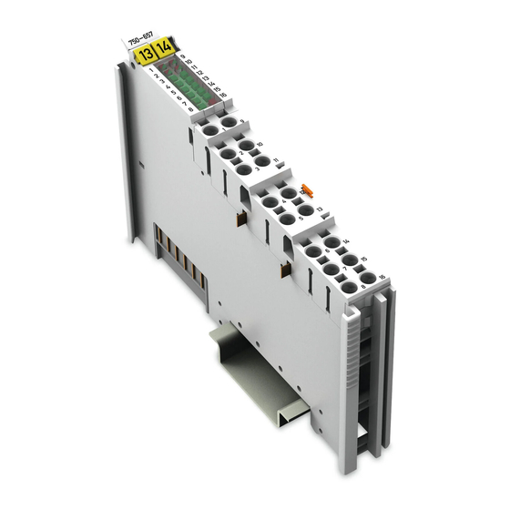
750-657
Version 1.0.2, valid from FW/HW-Version 02/01
Pos: 3 /Alle Serien (Allgemeine Module)/Hinweise zur Dokumentation/Impressum für Standardhandbücher - allg. Angaben, Anschriften, Telefonnummern und E-Mail-Adressen @ 3\mod_1219151118203_21.doc @ 21060 @ @ 1
Advertisement
Chapters
Table of Contents


Need help?
Do you have a question about the WAGO-I/O-SYSTEM 750 Series and is the answer not in the manual?
Questions and answers