Table of Contents
Advertisement
Quick Links
Pos : 2 /D okumentati on allgemein/Ei nband/Ei nband H andbuch - Fronts eite 2015 - mit Doc Variabl en (Standar d) @ 9\mod_1285229289866_0.doc x @ 64941 @ @ 1
WAGO-I/O-SYSTEM 750
Manual
750-633
Up/Down Counter Ex i
Version 1.3.0
HW-Version 03, SW-Version 01
Pos : 3 /Alle Serien (Allgemeine M odul e)/Rec htlic hes, Allgemei nes/Impressum für Standardhandbüc her - allg. Angaben, Ansc hriften, T elefonnummer n und E-Mail-Adres sen @ 3\mod_1219151118203_21.doc x @ 21060 @ @ 1
Advertisement
Chapters
Table of Contents

Subscribe to Our Youtube Channel
Related Manuals for WAGO 750-633


Summary of Contents for WAGO 750-633
- Page 1 Pos : 2 /D okumentati on allgemein/Ei nband/Ei nband H andbuch - Fronts eite 2015 - mit Doc Variabl en (Standar d) @ 9\mod_1285229289866_0.doc x @ 64941 @ @ 1 WAGO-I/O-SYSTEM 750 Manual 750-633 Up/Down Counter Ex i Version 1.3.0 HW-Version 03, SW-Version 01 Pos : 3 /Alle Serien (Allgemeine M odul e)/Rec htlic hes, Allgemei nes/Impressum für Standardhandbüc her - allg.
- Page 2 We wish to point out that the software and hardware terms as well as the trademarks of companies used and/or mentioned in the present manual are generally protected by trademark or patent. WAGO is a registered trademark of WAGO Verwaltungsgesellschaft mbH. === Ende der Liste für T extmar ke Ei nband_vorne === Manual...
-
Page 3: Table Of Contents
2.1.1 Subject to Changes ................9 2.1.2 Personnel Qualifications ............... 9 2.1.3 Use of the WAGO-I/O-SYSTEM 750 in Compliance with Underlying Provisions ................9 2.1.4 Technical Condition of Specified Devices ......... 10 Safety Advice (Precautions) ..............11 Device Description ..................13 View ...................... - Page 4 Connection Example ................47 Parameterizing ................... 48 Parameterization with WAGO-I/O-CHECK ........... 48 7.1.1 Up/Down Counter Ex i 750-633 (Parameter Dialog Box) ....48 7.1.1.1 Up/Down Counter Ex i 750-633 Toolbar ........49 7.1.1.2 Up/Down Counter Ex i 750-633 Parameter ........50 Use in Hazardous Environments ..............
-
Page 5: Notes About This Documentation
(Up/Down Counter Ex i). Pos : 11 /Serie 750 ( WAGO-I/O-SYST EM)/Hi nweis e z ur D okumentati on/Hi nweise/Ac htung: Hinweis z ur D okumentati on I/O-Modul e 750- xxxx @ 4\mod_1237986979656_21.doc x @ 29023 @ @ 1 The I/O module 750-633 shall only be installed and operated according to the instructions in this manual and in the manual for the used fieldbus coupler/controller. -
Page 6: Symbols
Notes about this Documentation WAGO-I/O-SYSTEM 750 750-633 Up/Down Counter Ex i Pos : 12.4 /All e Seri en ( Allgemei ne Module)/Ü bers chriften/Ebene 2/Symbol e - Ü berschrift 2 @ 13\mod_1351068042408_21.doc x @ 105270 @ 2 @ 1 Symbols Pos : 12.5.1 /All e Serien ( Allgemei ne Module)/Sicherheits- und sons tige Hi nweis e/Gefahr/Gefahr: _War nung vor Pers onenschäden allgemei n_ - Erläuter ung @ 13\mod_1343309450020_21.doc x @ 101029 @ @ 1... - Page 7 WAGO-I/O-SYSTEM 750 Notes about this Documentation 750-633 Up/Down Counter Ex i Additional Information: Refers to additional information which is not an integral part of this documentation (e.g., the Internet). Pos : 12.6 /Dokumentation allgemei n/Glieder ungs elemente/---Seitenwechs el--- @ 3\mod_1221108045078_0.doc x @ 21810 @ @ 1 Manual Version 1.3.0 HW-Version 03, SW-Version 01...
-
Page 8: Number Notation
WAGO-I/O-SYSTEM 750 750-633 Up/Down Counter Ex i Pos : 12.7 /All e Seri en ( Allgemei ne Module)/Ü bers chriften/Ebene 2/D arstellung der Z ahlens ys teme - Ü bers chrift 2 @ 23\mod_1435647128078_21.doc x @ 184811 @ 2 @ 1 Number Notation Pos : 12.8 /All e Seri en ( Allgemei ne Module)/R ec htliches , Allgemei nes /Zahlens ysteme @ 3\mod_1221059454015_21.doc x @ 21711 @ @ 1... -
Page 9: Important Notes
PLC programming. Pos : 15.5 /Serie 750 (WAGO-I/O-SYST EM)/Wic htige Erläuterungen/Bes timmungsgemäß e Verwendung/Besti mmungsgemäß e Ver wendung 750- xxxx - Übersc hrift 3 und Inhalt @ 3\mod_1224064151234_21.doc x @ 24070 @ 3 @ 1 2.1.3... -
Page 10: Technical Condition Of Specified Devices
Please send your request for modified and new hardware or software configurations directly to WAGO Kontakttechnik GmbH & Co. KG. Pos : 15.7 /Dokumentation allgemei n/Glieder ungs elemente/---Seitenwechs el--- @ 3\mod_1221108045078_0.doc x @ 21810 @ @ 1 Manual Version 1.3.0 HW-Version 03, SW-Version 01... -
Page 11: Safety Advice (Precautions)
Pos : 15.10.2 /Serie 750 ( WAGO-I/O- SYST EM)/Wic htig e Erl äuter ung en/Sic her hei ts- und s onstige Hi nweise/Gefahr/Gefahr: Ei nbau 0750- xxxx nur i n Gehäus en, Sc hränken oder el ektrisc hen Betriebsräumen! @ 6\mod_1260180556692_21.doc... - Page 12 Important Notes WAGO-I/O-SYSTEM 750 750-633 Up/Down Counter Ex i Do not use any contact spray! Do not use any contact spray. The spray may impair contact area functionality in connection with contamination. Pos : 15.11.5 /Alle Serien (Allgemeine M odul e)/Sic herheits- und s onstige Hinweise/Achtung/Ac htung: Ver pol ung en der D aten- und Versorgungsleitungen vermeiden! @ 6\mod_1260184045744_21.doc x @ 46767 @ @ 1...
-
Page 13: Device Description
Pos : 18.1.2 /Serie 750 (WAGO-I/O-SYST EM)/Wichtige Erläuterungen/Sic herheits- und sonstige Hinweis e/War nung/Warnung: Ex i Installati on des WAGO-I/O-SYST EM 750 nur in Zone 2 oder i m nicht-ex- Ber eich @ 5\mod_1245851655116_21.doc x @ 35947 @ @ 1... - Page 14 Pos : 18.1.12 /Serie 750 ( WAGO-I/O- SYST EM)/Gerätebeschr eibung/Einl eitung/Einsatzbereic h/Einsatzbereic h 750- xxxx alle Koppler/C ontroll er ohne Ec onomy- Koppler @ 3\mod_1232541867468_21.doc x @ 26525 @ @ 1 The I/O module 750-633 can be used with all fieldbus couplers/controllers of the WAGO-I/O-SYSTEM 750 (except for the economy types 750-320, -323, -324 and -327).
-
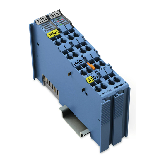
Page 15: View
Figure 1: View Pos : 18.5 /Serie 750 (WAGO-I/O-SYST EM)/Ger ätebesc hrei bung/Ansic ht/Ansic ht C ageCl amp® _Legende mit LEDs , mit 1 Entrieg elungslasc he @ 15\mod_1370867188922_21.doc x @ 122225 @ @ 1 Table 3: Legend for Figure “View”... -
Page 16: Connectors
Figure 2: Data Contacts Pos : 18.9.2 /Serie 750 (WAGO-I/O-SYST EM)/Wichtige Erläuterungen/Sic herheits- und sonstige Hinweis e/Achtung/Achtung: Bus kl emmen nic ht auf Gol dfeder kontakte leg en! @ 7\mod_1266318463636_21.doc x @ 50695 @ @ 1 Do not place the I/O modules on the gold spring contacts! -
Page 17: Power Jumper Contacts/Field Supply
Pos : 18.12.1 /Serie 750 ( WAGO-I/O- SYST EM)/Wic htig e Erl äuter ung en/Sic her hei ts- und s onstige Hi nweise/Vorsicht/Vorsic ht: Verletzungsgefahr durc h sc har fkantige Mes ser kontakte! @ 6\mod_1256193279401_21.doc... -
Page 18: Cage Clamp ® Connectors
Pos : 18.16 /Serie 750 ( WAGO-I/O-SYST EM)/Wichtig e Erl äuter ung en/Sic her hei ts- und s onstige Hinweise/Hinweis/Hi nweis : Gesc hir mte Sig nallei tungen für C LK und U/D( GAT E) verwenden! @ 12\mod_1340256527042_21.doc... -
Page 19: Display Elements
Pos : 18.20 /Alle Serien (Allgemeine M odul e)/Übersc hriften/Ebene 2/Bedienelemente - Übersc hrift 2 @ 4\mod_1239191655456_21.doc x @ 30439 @ 2 @ 1 Operating Elements Pos : 18.21 /Serie 750 ( WAGO-I/O-SYST EM)/Gerätebeschr eibung/Bedi enel emente/Bedienelemente I/O-Modul 75x- xxxx nic ht vor handen @ 4\mod_1236322031125_21.doc x @ 28063 @ @ 1 The I/O module 750-633 has no operating elements. -
Page 20: Schematic Diagram
Pos : 18.23 /Alle Serien (Allgemeine M odul e)/Übersc hriften/Ebene 2/Schematisc hes Schaltbild - Ü berschrift 2 @ 4\mod_1240984441312_21.doc x @ 31967 @ 2 @ 1 Schematic Diagram Pos : 18.24 /Serie 750 ( WAGO-I/O-SYST EM)/Gerätebeschr eibung/Sc hematis che Sc haltbilder/Sonder kl emmen/Schematisc hes Schaltbild 750- 0633 @ 10\mod_1314620807208_21.doc x @ 77454 @ @ 1 Figure 6: Schematic Diagram Pos : 18.25 /D okumentati on allgemei n/Gli ederungsel emente/---Seitenwec hs el--- @ 3\mod_1221108045078_0.doc x @ 21810 @ @ 1... -
Page 21: Technical Data
Pos : 18.26 /Alle Serien (Allgemeine M odul e)/Übersc hriften/Ebene 2/T ec hnisc he D aten - Übersc hrift 2 @ 3\mod_1232967587687_21.doc x @ 26924 @ 2 @ 1 Technical Data Pos : 18.27 /Serie 750 ( WAGO-I/O-SYST EM)/Gerätebeschr eibung/Tec hnische D aten/Sonder kl emmen/T ec hnisc he D aten 750- 0633 @ 10\mod_1314621127535_21.doc x @ 77458 @ 33333333 @ 1 3.6.1 Device Data Table 7: Technical Data ‒... -
Page 22: Counter
Device Description WAGO-I/O-SYSTEM 750 750-633 Up/Down Counter Ex i 3.6.4 Counter Table 10: Technical Data ‒ Counter Number of counters Operation modes 1: Counter with gate input 2: Up/down counter 3: Frequency counter with gate input 4: Peak time counter Switching rate 20 Hz …... -
Page 23: Explosion Protection Inputs
WAGO-I/O-SYSTEM 750 Device Description 750-633 Up/Down Counter Ex i 3.6.7 Explosion Protection Inputs Table 13: Technical Data ‒ Explosion Protection Inputs Voltage supply via power jumper = 27.3 V contacts ( LK1, LK2) = 3 W Interface circuit ( K-Bus) -
Page 24: Explosion Protection Outputs
Connection Type Pos : 18.28.2 /Serie 750 ( WAGO-I/O- SYST EM)/Gerätebeschr eibung/Tec hnische D aten/Ansc hl usstec hni k/Technisc he Daten Ver drahtungs ebene CC - 0,08 bis 2,5mm2 @ 17\mod_1380121238809_21.doc x @ 132780 @ @ 1 Table 15: Technical Data – Field Wiring ®... -
Page 25: Climatic Environmental Conditions
Pos : 18.29 /Serie 750 ( WAGO-I/O-SYST EM)/Gerätebeschr eibung/Tec hnische D aten/Klimatisc he U mgebungsbeding ungen/T ec hnische D aten Kli mat. U mgebungsbed. ohne erw. T emp. 0...55°C/- 25...+ 85°C @ 5\mod_1247657968368_21.doc x @ 37603 @ 3 @ 1... -
Page 26: Approvals
750 > System Description. Pos : 18.33 /Serie 750 ( WAGO-I/O-SYST EM)/Gerätebeschr eibung/Zul ass ung en/Allgemein/Zul ass ung en Bus klemme 750- xxxx Allgemei n, ohne Vari antenangabe - Einlei tung @ 4\mod_1237460656921_21.doc x @ 28643 @ @ 1 The following approvals have been granted to 750-633 I/O modules: Pos : 18.34 /Alle Serien (Allgemeine M odul e)/Z ulass ungen/Standar dz ulass ungen/CE (Konfor mitäts kennzeic hnung) @ 3\mod_1224494777421_21.doc x @ 24276 @ @ 1... - Page 27 18.42 /Dokumentati on allgemei n/Gli ederungsel emente/---Seitenwec hs el--- @ 3\mod_1221108045078_0.doc x @ 21810 @ @ 1 Pos : 18.43 /Serie 750 ( WAGO-I/O-SYST EM)/Gerätebeschr eibung/Zul ass ung en/Sc hiff/Ei nleitungssätze/Zul ass ungen I/O-Modul 750-xxxx Sc hiff, ohne Variantenangabe - Ei nleitung @ 4\mod_1237190918453_21.doc x @ 28420 @ @ 1 The following ship approvals have been granted to 750-633 I/O modules: Pos : 18.44 /Alle Serien (Allgemeine M odul e)/Z ulass ungen/Schiffsz ulas sungen/BSH ( Bundes amt für Seesc hifffahrt und H ydrogr aphie) @ 5\mod_1246341825156_21.doc x @ 36334 @ @ 1...
-
Page 28: Standards And Guidelines
Standards and Guidelines Pos : 18.48 /Serie 750 ( WAGO-I/O-SYST EM)/Gerätebeschr eibung/Nor men und Richtlinien/N or men und Richtlinien I/O-M odul 750- xxxx, ohne Vari antenangabe - Einl eitung @ 7\mod_1274278887584_21.doc x @ 56645 @ @ 1 750-633 I/O modules meet the following standards and guidelines: Pos : 18.49 /Alle Serien (Allgemeine M odul e)/Nor men und Ric htlini en/Ex(i)-Nor men/AT EX-Ric htli nie 2014/34/EU @ 19\mod_1404197489184_21.doc x @ 157133 @ @ 1... - Page 29 WAGO-I/O-SYSTEM 750 Device Description 750-633 Up/Down Counter Ex i Explosive atmospheres CAN/CSA-C22.2 No. 60079-11 Equipment Protection by Intrinsic Safety "i" Pos : 18.65 /Alle Serien (Allgemeine M odul e)/Nor men und Ric htlini en/Ex(i)-Nor men/Explosionsfähige Atmosphär e C AN/C SA_C 22.2 N o. 60079-15 @ 29\mod_1496144140008_21.doc x @ 423345 @ @ 1 Explosive atmospheres CAN/CSA-C22.2 No.
-
Page 30: Process Image
Process Image Pos : 21 /Serie 750 ( WAGO-I/O-SYST EM)/Proz ess abbild Kl emmenbus /Hinweis: Prozes sabbildmapping abhängig von FBK/PFC, ohne Status-/C ontr olbyte @ 6\mod_1256126797251_21.doc x @ 43340 @ @ 1 Mapping of process data in the process image of fieldbus systems The representation of the process data of some I/O modules or their variants in the process image depends on the fieldbus coupler/controller used. -
Page 31: Set Counter
WAGO-I/O-SYSTEM 750 Process Image 750-633 Up/Down Counter Ex i Table 21: Status Byte S0, Operating Mode 1/2 Bit 7 Bit 6 Bit 5 Bit 4 Bit 3 Bit 2 Bit 1 Bit 0 NAMUR_ ST_U/D CNT_SET CNT_INH ST_DO ST_CLK (GATE) - Page 32 Process Image WAGO-I/O-SYSTEM 750 750-633 Up/Down Counter Ex i Status Byte S0 Input bit Bit 7 Bit 6 Bit 5 Bit 4 Bit 3 Bit 2 Bit 1 Bit 0 Value Clear bit 5 (set counter) in the control byte to complete the handshake.
-
Page 33: Operating Mode 3 - Frequency Counter
WAGO-I/O-SYSTEM 750 Process Image 750-633 Up/Down Counter Ex i Operating Mode 3 – Frequency Counter The Watchdog time to be set is stored in binary format in the 2 output bytes (D0, D1). The output bytes (D2, D3) are not used. In the 4 input bytes (D0 ... D3), the frequency value is stored in binary format. -
Page 34: Set Measuring Method, Frequency Range And Measured Value Display
Process Image WAGO-I/O-SYSTEM 750 750-633 Up/Down Counter Ex i 4.2.1 Set Measuring Method, Frequency Range and Measured Value Display The RANGE_SEL REQ bits in the control byte are used to set the measurement methods and display of the frequency value. The maximum frequency value also changes depending on the measuring method set. -
Page 35: Set Output
WAGO-I/O-SYSTEM 750 Process Image 750-633 Up/Down Counter Ex i This process is started by writing the respective value to output bytes D1 and D0 before the T _REQ bit is written to the control byte. A successful parameter transfer is confirmed by the T _ACK bit in the status byte. -
Page 36: Operating Mode 4 - Peak-Time Counter
Process Image WAGO-I/O-SYSTEM 750 750-633 Up/Down Counter Ex i Operating Mode 4 – Peak-Time Counter In the 4 input bytes (D0 ... D3), the value of the counter is stored in binary format. Control byte C0 is used to start periodic counting and to set the outputs. Status byte S0 shows the counter status and the status of the inputs and outputs. -
Page 37: Example
WAGO-I/O-SYSTEM 750 Process Image 750-633 Up/Down Counter Ex i 4.3.2 Example The count direction is up (input U/D = 24 V). The counter value is 0. The timer is stopped. No pulses are detected on the CLK input. Control Byte C0... - Page 38 Process Image WAGO-I/O-SYSTEM 750 750-633 Up/Down Counter Ex i Control Byte C0 Output bit Bit 7 Bit 6 Bit 5 Bit 4 Bit 3 Bit 2 Bit 1 Bit 0 Value Status Byte S0 Input bit Bit 7 Bit 6...
-
Page 39: Mounting
I/O modules with fewer power contacts. Pos : 25.2 /Serie 750 (WAGO-I/O-SYST EM)/Wic htige Erläuterungen/Sicherheits- und sonstig e Hinweis e/Vorsic ht/Vorsicht: Verl etz ungsgefahr durc h s charfkantige M ess er kontakte! @ 6\mod_1256193279401_21.doc x @ 43414 @ @ 1 Risk of injury due to sharp-edged blade contacts! The blade contacts are sharp-edged. -
Page 40: Inserting And Removing Devices
Working on energized devices can damage them. Therefore, turn off the power supply before working on the devices. Pos : 25.8 /Serie 750 (WAGO-I/O-SYST EM)/M ontieren/D emontieren/I/O-Modul einfüg en @ 3\mod_1231769726703_21.doc x @ 25989 @ 3 @ 1 5.2.1 Inserting the I/O Module... -
Page 41: Removing The I/O Module
WAGO-I/O-SYSTEM 750 Mounting 750-633 Up/Down Counter Ex i Pos : 25.10 /Serie 750 ( WAGO-I/O-SYST EM)/Monti eren/D emonti eren/I/O-M odul entfer nen @ 4\mod_1239169375203_21.doc x @ 30334 @ 3 @ 1 5.2.2 Removing the I/O Module Remove the I/O module from the assembly by pulling the release tab. -
Page 42: Connect Devices
Connect Devices Pos : 28 /Serie 750 ( WAGO-I/O-SYST EM)/Ans chli eßen/Leiter an C AGE C LAM P ans chli eßen ( allgemei n) - Übersc hrift 2 und Text @ 3\mod_1225448660171_21.doc x @ 24928 @ 2 @ 1 ®... -
Page 43: Power Supply Concept
Pos : 31.3 /Serie 750 (WAGO-I/O-SYST EM)/Wic htige Erläuterungen/Sicherheits- und sonstig e Hinweis e/Hinweis/Hi nweis: M axi mal er Strom Ex i Ei ns peis ung 750- 06xx 1,0 A @ 7\mod_1274358256668_21.doc x @ 56898 @ @ 1... -
Page 44: Figure 11: Supply Principle Ex I
Pos : 31.8 /Dokumentation allgemei n/Glieder ungs elemente/---Leerabs atz-(2Z)--- @ 3\mod_1224662755687_0.doc x @ 24460 @ @ 1 Pos : 31.9.1 /Serie 750 (WAGO-I/O-SYST EM)/Ansc hließen/Eins peisekonz epte/Einspeis ung bei Ei nsatz i m Sc hiffs bereic h - Ü bersc hrift 3 @ 19\mod_1404808499227_21.doc x @ 157554 @ 3 @ 1 Manual Version 1.3.0 HW-Version 03, SW-Version 01... -
Page 45: Power Supply Concept In Marine Applications
Power Supply Concept in Marine Applications Pos : 31.9.2 /Serie 750 (WAGO-I/O-SYST EM)/Wichtige Erläuterungen/Sic herheits- und sonstige Hinweis e/War nung/Warnung: Ex-i-Sc hiffsei ns peis ung nur mit Filter modul EMC 1 und 2 Entwurf @ 19\mod_1396609785412_21.doc x @ 150873 @ @ 1... -
Page 46: Figure 14: Power Supply Concept, Category Emc2 (Marine Applications)
Connect Devices WAGO-I/O-SYSTEM 750 750-633 Up/Down Counter Ex i Figure 14: Power Supply Concept, Category EMC2 (Marine Applications) Table 31: Legend for Figure “Power Supply Concept, Category EMC2 (Marine Applications)” Pos. Explanation Fieldbus coupler/controller Filter module (750-626, 750-626/020-000, 750-624, 750-624/020-000) -
Page 47: Connection Example
Figure 15: Connection Example for U/D (GATE), CLK and DO Pos : 35 /Serie 750 ( WAGO-I/O-SYST EM)/Wic htige Erläuterungen/Sicherheits- und sonstig e Hinweis e/Hi nweis /Hinweis: Geschir mte Signalleitung en für CLK und U /D(GATE) ver wenden! @ 12\mod_1340256527042_21.doc x @ 98164 @ @ 1 Use shielded signal lines! Only use shielded signal lines for CLK and U/D (GATE) inputs. -
Page 48: Parameterizing
Parameterization with WAGO-I/O-CHECK Pos : 39 /Serie 759 ( WAGO-Softwar e)/WAGO-I/O-CHEC K/750- 0633 Vor-/R üc kwärtsz ähl er Ex i /Vor-/Rüc kwärts zähler Ex i 750- 0633 (Parametri erdi alog) @ 12\mod_1332408819566_21.doc x @ 91831 @ 3 @ 1 7.1.1... -
Page 49: Up/Down Counter Ex I 750-633 Toolbar
750-633 Up/Down Counter Ex i Pos : 41 /Serie 759 ( WAGO-Softwar e)/WAGO-I/O-CHEC K/750- 0633 Vor-/R üc kwärtsz ähl er Ex i /Vor-/Rüc kwärts zähler Ex i 750- 0633 Symbolleis te @ 12\mod_1332409042839_21.doc x @ 91834 @ 4 @ 1 7.1.1.1... -
Page 50: Up/Down Counter Ex I 750-633 Parameter
750-633 Up/Down Counter Ex i Pos : 43 /Serie 759 ( WAGO-Softwar e)/WAGO-I/O-CHEC K/750- 0633 Vor-/R üc kwärtsz ähl er Ex i /Vor-/Rüc kwärts zähler Ex i 750- 0633 Par ameter @ 12\mod_1332409302876_21.doc x @ 91837 @ 4 @ 1 7.1.1.2... -
Page 51: Use In Hazardous Environments
Use in Hazardous Environments Pos : 45.2 /Serie 750 (WAGO-I/O-SYST EM)/Eins atz in Ex- Ber eichen/Ei ns atz ber eich Serie 750 @ 3\mod_1234272230203_21.doc x @ 27500 @ @ 1 The WAGO-I/O-SYSTEM 750 (electrical equipment) is designed for use in Zone 2 hazardous areas. -
Page 52: Marking Configuration Examples
Marking for Europe According to ATEX and IECEx Pos : 45.6 /Serie 750 (WAGO-I/O-SYST EM)/Eins atz in Ex- Ber eichen/Beis piel bedruc kung ATEX und IEC Ex_TUEV07_2017 @ 14\mod_1360569228625_21.doc x @ 111294 @ @ 1 Figure 19: Marking Example According to ATEX and IECEx Figure 20: Text Detail –... -
Page 53: Table 34: Description Of Marking Example According To Atex And Iecex
WAGO-I/O-SYSTEM 750 Use in Hazardous Environments 750-633 Up/Down Counter Ex i Table 34: Description of Marking Example According to ATEX and IECEx Marking Description TUEV 07 ATEX 554086 X Approving authority resp. certificate numbers IECEx TUN 09.0001 X Dust Equipment group: All except mining... -
Page 54: Figure 21: Marking Example For Approved Ex I I/O Module According To Atex And Iecex
750-633 Up/Down Counter Ex i Pos : 45.8 /Serie 750 (WAGO-I/O-SYST EM)/Eins atz in Ex- Ber eichen/Beis piel bedruc kung ATEX und IEC Ex_TUEV12_Ex i_2017 @ 14\mod_1360569320118_21.doc x @ 111298 @ @ 1 Figure 21: Marking Example for Approved Ex i I/O Module According to ATEX and IECEx Figure 22: Text Detail –... -
Page 55: Table 35: Description Of Marking Example For Approved Ex I I/O Module According To Atex And Iecex
WAGO-I/O-SYSTEM 750 Use in Hazardous Environments 750-633 Up/Down Counter Ex i Table 35: Description of Marking Example for Approved Ex i I/O Module According to ATEX and IECEx Marking Description TUEV 12 ATEX 106032 X Approving authority resp. certificate numbers... -
Page 56: Marking For America (Nec) And Canada (Cec)
Figure 23: Marking Example According to NEC Pos : 45.11 /Serie 750 ( WAGO-I/O-SYST EM)/Ei ns atz i n Ex-Bereic hen/Beispi elbedruc kung und Textdetail N EC 500_2017 @ 14\mod_1360580302684_21.doc x @ 111353 @ @ 1 Figure 24: Text Detail – Marking Example According to NEC 500... -
Page 57: Figure 25: Text Detail - Marking Example For Approved Ex I I/O Module
750-633 Up/Down Counter Ex i Pos : 45.13 /Serie 750 ( WAGO-I/O-SYST EM)/Ei ns atz i n Ex-Bereic hen/Beispi elbedruc kung und Textdetail N EC 505_2017 @ 29\mod_1497865583500_21.doc x @ 424739 @ @ 1 Figure 25: Text Detail – Marking Example for Approved Ex i I/O Module According to NEC 505... -
Page 58: Figure 27: Text Detail - Marking Example For Approved Ex I I/O Modules
750-633 Up/Down Counter Ex i Pos : 45.16 /Serie 750 ( WAGO-I/O-SYST EM)/Ei ns atz i n Ex-Bereic hen/Beispi elbedruc kung und Textdetail C EC_2017 @ 29\mod_1497865583297_21.doc x @ 424736 @ @ 1 Figure 27: Text Detail – Marking Example for Approved Ex i I/O Modules According to CEC 18... -
Page 59: Installation Regulations
Special Notes Regarding Explosion Protection Pos : 45.21.2 /Serie 750 ( WAGO-I/O- SYST EM)/Ei nsatz i n Ex-Bereic hen/Besonder e Hi nweis e hinsic htlic h Explosi onssc hutz_2017 @ 29\mod_1491556994025_21.doc x @ 415448 @ @ 1 The following warning notices are to be posted in the immediately proximity of the WAGO-I/O-SYSTEM 750 (hereinafter “product”):... - Page 60 Use in Hazardous Environments WAGO-I/O-SYSTEM 750 750-633 Up/Down Counter Ex i Explosive atmosphere occurring simultaneously with assembly, installation or repair work must be ruled out. Among other things, these include the following activities • Insertion and removal of components •...
-
Page 61: Special Notes Regarding Ansi/Isa Ex
Special Notes Regarding ANSI/ISA Ex Pos : 45.21.5 /Serie 750 ( WAGO-I/O- SYST EM)/Ei nsatz i n Ex-Bereic hen/AN SI/ISA gemäß U L Fil e E198726_2017 @ 29\mod_1491557259544_21.doc x @ 415451 @ @ 1 For ANSI/ISA Ex acc. to UL File E198726, the following additional requirements apply: •... -
Page 62: Appendix
Pos : 47 /All e Seri en (Allgemei ne Module)/Ü berschriften/Ebene 1/Anhang - Übersc hrift 1 @ 4\mod_1239874070437_21.doc x @ 30560 @ 1 @ 1 Appendix Pos : 48 /Serie 750 ( WAGO-I/O-SYST EM)/Anhang/Bemess ungs toß spannung @ 19\mod_1397126071203_21.doc x @ 151298 @ 2 @ 1 Rated Surge Voltage... -
Page 63: List Of Figures
Figure 14: Power Supply Concept, Category EMC2 (Marine Applications) ..46 Figure 15: Connection Example for U/D (GATE), CLK and DO ......47 Figure 16: Up/Down Counter Ex i 750-633 (Parameter Dialog Box) ....48 Figure 17: Up/Down Counter Ex i 750-633 Toolbar ..........49 Figure 18: Up/Down Counter Ex i 750-633 Parameter ......... -
Page 64: List Of Tables
Table 31: Legend for Figure “Power Supply Concept, Category EMC2 (Marine Applications)” ................46 Table 32: Up/Down Counter Ex i 750-633 Toolbar ..........49 Table 33: Up/Down Counter Ex i 750-633 Parameter .......... 50 Table 34: Description of Marking Example According to ATEX and IECEx ..53 Table 35: Description of Marking Example for Approved Ex i I/O Module According to ATEX and IECEx .............. - Page 65 WAGO-I/O-SYSTEM 750 List of Tables 750-633 Up/Down Counter Ex i === Ende der Liste für T extmar ke Verzeic hnis_hi nten === Manual Version 1.3.0 HW-Version 03, SW-Version 01...
- Page 66 Pos : 54 /D okumentation allgemei n/Einband/Einband - Leers eite für durc h 2 teilbare Seitenz ahl (Standarddruc k) @ 3\mod_1219230851078_0.doc x @ 21123 @ @ 1 Pos : 55 /D okumentation allgemei n/Einband/Einband H andbuc h - R üc kseite 2015 @ 9\mod_1285229376516_21.doc x @ 64944 @ @ 1 WAGO Kontakttechnik GmbH & Co. KG Postfach 2880 •...
Need help?
Do you have a question about the 750-633 and is the answer not in the manual?
Questions and answers