
Related Manuals for WAGO 750-654


Summary of Contents for WAGO 750-654
- Page 1 Fieldbus Independent I/O Modules Data Exchange Module 750-654 Manual Version 1.0.1...
- Page 2 • General Copyright 2006 by WAGO Kontakttechnik GmbH & Co. KG All rights reserved. WAGO Kontakttechnik GmbH & Co. KG Hansastraße 27 D-32423 Minden Phone: +49 (0) 571/8 87 – 0 Fax: +49 (0) 571/8 87 – 1 69 E-Mail: info@wago.com...
-
Page 3: Table Of Contents
Intended Use ..................4 Symbols ....................5 Number Notation..................5 Safety Notes ..................... 6 Scope ......................6 2 I/O Modules ....................7 Special Modules ..................7 2.1.1 750-654 [Data Exchange Module] ............7 2.1.1.1 View....................7 2.1.1.2 Variations..................7 2.1.1.3 Description..................7 2.1.1.4 Display Elements ................ -
Page 4: Important Comments
WAGO Kontakttechnik GmbH & Co. KG declines all liability resulting from improper action and damage to WAGO products and third party products due to non-observance of the information contained in this manual. -
Page 5: Symbols
Routines or advice for efficient use of the device and software optimization. More information References on additional literature, manuals, data sheets and INTERNET pages 1.3 Number Notation Number Code Example Note Decimal normal notation Hexadecimal 0x64 C notation Binary '100' Within ', '0110.0100' Nibble separated with dots WAGO-I/O-SYSTEM 750 I/O Modules... -
Page 6: Safety Notes
(persons, workplace and packing) is well grounded. Avoid touching conductive components, e.g. gold contacts. 1.5 Scope This manual describes the Special Module 750-654 Data Exchange Module of the modular WAGO-I/O-SYSTEM 750. Handling, assembly and start-up are described in the manual of the Fieldbus Coupler. -
Page 7: O Modules
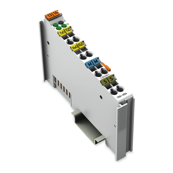
Function Data contacts Common Common (ground) (ground) Shield Shield (screen) (screen) 750-654 Fig. 2.1.1-1: Data Exchange Module 750-654 g065400e 2.1.1.2 Variations Item-No. Designation Description 750-654 Data Exchange Module Baud rate: 62500 baud; Parity: none; data bits: 8, stop bits: 1 750-654/000-001 Data Exchange Module Baud rate: 125000 baud;... -
Page 8: Display Elements
4 (5) bytes, one status byte and one control byte between the fieldbus systems via multiplexing of a serial connection. The delay which is caused by the multiplexor is ca. 5 ms with the module 750-654 and 2.5 ms with the module 750-654/000-001. -
Page 9: Schematic Diagram
750-654 [Data Exchange Module] • 9 Schematic Diagram 2.1.1.5 Schematic Diagram RS 485 Logic Function Shield Shield (screen) (screen) 750-654 Fig. 2.1.1-3: Data Exchange Module 750-654 g065401e WAGO-I/O-SYSTEM 750 I/O Modules... -
Page 10: Technical Data
NKK (Nippon Kaiji Kyokai) Conformity Marking More Information Detailed references to the approvals are listed in the document "Overview Approvals WAGO-I/O-SYSTEM 750", which you can find on the CD ROM ELECTRONICC Tools and Docs (Item-No.: 0888-0412) or in the internet under: www.wago.com... -
Page 11: Functional Description
750-654 [Data Exchange Module] • 11 Functional description 2.1.1.7 Functional description The integrated watchdog function switches all outputs to zero if there is no valid information for more than 200 ms via the multiplex connection. The 128 bytes input buffer provides for high rates of data transmission. When using slower speeds, you can collect the received data with lower priority without loosing data. -
Page 12: Process Image
2.1.1.8 Process Image Using the module 750-654, a 6 byte input and output process image can be transferred to the fieldbus coupler / controller via one logical channel. The data sent and received are stored in up to 5 output and input bytes (D0 ... D4). -
Page 13: Data Transfer
750-654 [Data Exchange Module] • 13 Data Transfer 2.1.1.9 Data Transfer The status byte is used as diagnostic byte for the data communication and indicates the status of data communication with the partner module. Control of the multiplex connection: In the process image of the transmitting coupler/controller, one bit is set to "1"... - Page 14 WAGO Kontakttechnik GmbH & Co. KG Postfach 2880 • D-32385 Minden Hansastraße 27 • D-32423 Minden Phone: 05 71/8 87 – 0 Fax: 05 71/8 87 – 1 69 E-Mail: info@wago.com Internet: http://www.wago.com...
Need help?
Do you have a question about the 750-654 and is the answer not in the manual?
Questions and answers