
Subscribe to Our Youtube Channel
Related Manuals for WAGO 750-645


Summary of Contents for WAGO 750-645
- Page 1 Fieldbus Independent I/O Modules 2AI/2DO VIB VRMS/SPM Multi 750-645 Manual Version 1.2.1...
- Page 2 • General Copyright 2008 by WAGO Kontakttechnik GmbH & Co. KG All rights reserved. WAGO Kontakttechnik GmbH & Co. KG Hansastraße 27 D-32423 Minden Phone: +49 (0) 571/8 87 – 0 Fax: +49 (0) 571/8 87 – 1 69 E-Mail: info@wago.com...
-
Page 3: Table Of Contents
Installation Errors or Insufficient Lubrication ......20 2.2.5.4 Dry-Run or Cavitation ..............20 2.2.6 The Measuring Point ................. 21 3 Overview Condition Monitoring Components 750-645, 750-925 ..24 4 I/O Modules ....................25 Special Modules ..................25 4.1.1 750-645 [2AI/2DO VIB VRMS/SPM Multi] ........25 4.1.1.1... - Page 4 Overview .................. 36 4.1.1.7.2 Control and Status Byte in Process Data Communication..37 4.1.1.8 Setting the 750-645 Module Using Register Communication..42 4.1.1.8.1 Control- and Status Byte at Register Communication ..... 44 4.1.1.9 Setting the 750-645 Module with WAGO-I/O-CHECK 2.... 46 5 Accessories ....................
-
Page 5: Important Notes
WAGO Kontakttechnik GmbH & Co. KG, Minden. Non-observance will entail the right of claims for damages. WAGO Kontakttechnik GmbH & Co. KG reserves the right of changes serving technical progress. All rights developing from the issue of a patent or the legal protection of utility patents are reserved to WAGO Kontakttechnik GmbH &... -
Page 6: Conforming Use Of Series 750
All personnel must be familiar with the applicable standards. WAGO Kontakttechnik GmbH & Co. KG declines any liability resulting from improper action and damage to WAGO products and third party products due to non-observance of the information contained in this manual. -
Page 7: Standards And Regulations For Operating The 750 Series
(emissions of interference) according to EN 61000-6-3. You will find the relevant information in the section on "WAGO-I/O-SYSTEM 750" "System Description" "Technical Data". Please observe the safety measures against electrostatic discharge according to DIN EN 61340-5-1/-3. -
Page 8: Symbols
Observe the precautionary measure for handling components at risk of electrostatic discharge. Note Make important notes that are to be complied with so that a trouble-free and efficient device operation can be guaranteed. Additional Information References to additional literature, manuals, data sheets and internet pages. WAGO-I/O-SYSTEM 750 I/O-Modules... -
Page 9: Safety Information
Danger The WAGO-I/O-SYSTEM 750 and its components are an open system. It must only be assembled in housings, cabinets or in electrical operation rooms. Access is only permitted via a key or tool to authorized qualified personnel. -
Page 10: Font Conventions
1.7 Scope This manual describes the Special Module 750-645 2AI/2DO VIB VRMS/SPM Multi of the modular WAGO-I/O-SYSTEM 750. Handling, assembly and start-up are described in the manual of the Fieldbus Coupler. Therefore this documentation is valid only in the connection with the appropriate manual. -
Page 11: Condition Monitoring
The continuous registration of the machine health condition via the fieldbus permits an early analysis and reaction prior to the actual occurrence of damages. For this purpose, WAGO offers the WAGO-I/O-SYSTEM function modules for recording and processing of the relevant parameters, such as current, temperature, standard signals and machine vibrations. - Page 12 A, B: Continuous measuring in regular time intervals. C: Determination of the cause of vibration and exact observation of the machine. Plan for shut-down. D: Immediate measures are required: localization of the cause, machine shut-down and problem correction. WAGO-I/O-SYSTEM 750 I/O-Modules...
-
Page 13: Roller Bearing Analysis
- such as those caused by alignment or balancing errors. The remaining signal portions are processed by the computer to obtain various shock impulse parameters that are described in the following pages. WAGO-I/O-SYSTEM 750 I/O-Modules... -
Page 14: Shock Impulse Evaluation
If the rolling path and roller bearings are separated by a complete and sufficient lubrication layer, the carpet value is low. This is shown in the following diagram. WAGO-I/O-SYSTEM 750 I/O-Modules... -
Page 15: The Shock Impulse Peak Value
(decibel maximum value). The peak value ( ) provides information to the operating conditions of a bearing and already existing bearing damages. The following diagram shows shock impulses indicating a bearing damage. WAGO-I/O-SYSTEM 750 I/O-Modules... -
Page 16: Damage History
Fig. 2.2.4-1: Lifespan curve g064510e Low deviations of the measured values are quite normal. They can be caused by temperature changes, changes in bearing load, the time passed since the last lubrication and other influences during operation. WAGO-I/O-SYSTEM 750 I/O-Modules... -
Page 17: The Evaluation Scale
A low carpet value indicates that the installation, lubrication and load are normal. 2.2.4.2.2 Limited Operating Condition A significant increase of both values is a first warning signal. A bearing damage in the making only appears during limited operating condition. The WAGO-I/O-SYSTEM 750 I/O-Modules... -
Page 18: Poor Operating Condition
Time Fig. 2.2.4-4: Poor operating condition g064513e When the peak values are in poor operating condition and the peak values are approx. three times the carpet value, the risk of a bearing damage is very high. WAGO-I/O-SYSTEM 750 I/O-Modules... -
Page 19: Typical Shock Impulse Diagrams
The bearing should be re-lubricated or the lubricant requires analysis, prior to the decision of a bearing exchange. poor limited good Time Fig. 2.2.5-2: Bearing damage or foreign matter in the lubricant g064515e WAGO-I/O-SYSTEM 750 I/O-Modules... -
Page 20: Installation Errors Or Insufficient Lubrication
In the case of cavitation, the values close to the pump enclosure will be the highest, or will oscillate with the operating point (pressure). poor limited good Time Fig. 2.2.5-4: Dry-run or cavitation g064517e WAGO-I/O-SYSTEM 750 I/O-Modules... -
Page 21: The Measuring Point
Every additional material transition dampens and/or reflects the signal to be measured. The signal path should have one material transition maximum, between bearing and bearing enclosure. Fig. 2.2.6-1: One material transition g064524x Note Signal losses due to addition material transitions can be significant (i.e., partition lines). WAGO-I/O-SYSTEM 750 I/O-Modules... - Page 22 For this reason, measurements should be taken within the load zone of the bearing, if possible. The load zone is defined by the emission window (see also illustration below). The ideal situation is the measuring point right in the emission window. WAGO-I/O-SYSTEM 750 I/O-Modules...
- Page 23 This area is defined as emission window. Outside an emission window, weakened and reflected signals are measured. These measurements permit trend tracking and comparisons, but will not provide for accurate statements to the lubrication state or possible bearing damages. WAGO-I/O-SYSTEM 750 I/O-Modules...
-
Page 24: Overview Condition Monitoring Components 750-645, 750-925
24 • Overview Condition Monitoring Components 750-645, 750-925 Machine Condition Monitoring with VIB-I/O Modules 4. Measurements as Close to the Bearing as Possible Shock impulses are weakened by extended measuring paths and material interruptions. Hence, shock impulses should be recorded before an important portion of the signal strength is lost. -
Page 25: O Modules
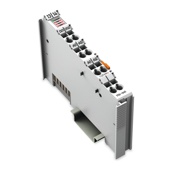
750-645 [2AI/2DO VIB VRMS/SPM Multi] • 25 View 4 I/O Modules 4.1 Special Modules 4.1.1 750-645 [2AI/2DO VIB VRMS/SPM Multi] 2 channel vibration strength / roller bearing monitoring VIB I/O 4.1.1.1 View 13 14 Status Data contacts DO1 DO2 DO 1... - Page 26 26 • 750-645 [2AI/2DO VIB VRMS/SPM Multi] Description ® A special Tandem-Piezo acceleration sensor at the same time, provides the measurement of machine vibrations and high-frequency shock impulse signals. The sensor is connected to +AI1 and -AI1 or +AI2 und -AI2 respectively.
- Page 27 750-645 [2AI/2DO VIB VRMS/SPM Multi] • 27 Description This description applies to the hardware and software version XXXX????..The version is specified in the manufacturing number, which is part of the lateral marking on the module. WAGO-I/O-SYSTEM 750 I/O-Modules...
-
Page 28: Display Elements
28 • 750-645 [2AI/2DO VIB VRMS/SPM Multi] Display Elements 4.1.1.3 Display Elements Channel Name State Function System not OK System SYS ok state green System OK Channel 1 Alarm threshold RMS and SPM not Alarm exceeded Alarm 1 threshold Channel 1... -
Page 29: Schematic Wiring Diagram
750-645 [2AI/2DO VIB VRMS/SPM Multi] • 29 Schematic Wiring Diagram 4.1.1.4 Schematic Wiring Diagram DO 1 (SYS ok) DO 2 (Alarm) +AI 1 (LD) +AI 2 (LD) 24 V -AI 2 (LD) -AI 1 (LD) 750-645 Fig.. 4.1.1-2: Schematic wiring diagram... -
Page 30: Technical Data
30 • 750-645 [2AI/2DO VIB VRMS/SPM Multi] Technical Data 4.1.1.5 Technical Data Inputs Number of inputs 2 (+AI1/-AI1, +AI2/-AI2) Sensor supply Line drive Cable length 30 m max. Measuring range Vibration speed (RMS) 0 ... 100 mm/s Shock impulse (SPM) -10 ... - Page 31 750-645 [2AI/2DO VIB VRMS/SPM Multi] • 31 Technical Data The following Ex approvals have been granted to the basic version of 750-645 I/O modules: TÜV 07 ATEX 554086 X I M2 Ex db I Mb II 3 G Ex nAc IIC T4 Gc II 3 D Ex tc IIIC T135°C Dc...
-
Page 32: Function Description
32 • 750-645 [2AI/2DO VIB VRMS/SPM Multi] Function Description 4.1.1.6 Function Description The VIB-I/O module is equipped with a self-monitoring function recognizing a short-circuit at the sensor or an open circuit in the signal path. These faults are signaled after approx. 1-2 seconds via the 'Sys ok'-LED at the module and output via the corresponding 'System OK'-output, independent from the defined delay time. -
Page 33: Operating Mode
4.1.1.6.1.2 Measuring Process in 2-Channel Mode IIn 2-channel mode, using two sensors in both active channels (configurable using WAGO-I/O-CHECK), the sensor measurement data of these two channels is processed sequentially. a) After channel switchover internally, the settling time (tS) of 10 seconds runs only in one channel. - Page 34 34 • 750-645 [2AI/2DO VIB VRMS/SPM Multi] Function Description b) The actual measurement period (tM) of 20 seconds then begins. Control process data is updated during this period. c, d) NChannel switchover takes place after 30 seconds. The process data of the channel active up to this time are frozen at the last valid process value.
-
Page 35: Parameter Vibration Monitoring (Rms)
750-645 [2AI/2DO VIB VRMS/SPM Multi] • 35 Function Description 4.1.1.6.2 Parameter Vibration Monitoring (RMS) The following parameters can be defined for each channel for the vibration monitoring: · Lower limiting frequency (2 Hz or 10 Hz) · Alarm threshold (0 mm/s ... measuring range end value) ·... -
Page 36: Process Image
750-645 [2AI/2DO VIB VRMS/SPM Multi] Process Image 4.1.1.7 Process Image The 750-645 I/O module provides the fieldbus coupler/controller 12 byte input and output process image via 4 logical channels. The measuring values for channel 1 are transmitted via the data bytes D0 and D1, or D4 and D5, respectively, and the measuring values for channel 2 are transmitted via the data bytes D2 and D3 or D6 and D7, respectively. -
Page 37: Control And Status Byte In Process Data Communication
750-645 [2AI/2DO VIB VRMS/SPM Multi] • 37 Process Image 4.1.1.7.2 Control and Status Byte in Process Data Communication For process data communication, Bit 7 (REG_COM) must be set to '0' in the corresponding control byte. Control and status bytes will then be assigned as... - Page 38 38 • 750-645 [2AI/2DO VIB VRMS/SPM Multi] Process Image Status byte S0 Bit 7 Bit 6 Bit 5 Bit 4 Bit 3 Bit 2 Bit 1 Bit 0 REG_ ERROR ALARM ERR_ WRN_ SYS_ SYS_OK System OK, System-OK output is set...
- Page 39 750-645 [2AI/2DO VIB VRMS/SPM Multi] • 39 Process Image Status byte S1 Bit 7 Bit 6 Bit 5 Bit 4 Bit 3 Bit 2 Bit 1 Bit 0 REG_ ERROR ALARM ERR_ WRN_ SYS_ SYS_OK System OK, System-OK output is set...
- Page 40 40 • 750-645 [2AI/2DO VIB VRMS/SPM Multi] Process Image Status byte S2 Bit 7 Bit 6 Bit 5 Bit 4 Bit 3 Bit 2 Bit 1 Bit 0 REG_ ERROR RMS_ SENS_ SPM_ SPM_ RMS_ RMS_ SPM_ ERR_ WRN_ WRN_...
- Page 41 750-645 [2AI/2DO VIB VRMS/SPM Multi] • 41 Process Image Status byte S3 Bit 7 Bit 6 Bit 5 Bit 4 Bit 3 Bit 2 Bit 1 Bit 0 REG_ ERROR RMS_ SENS_ SPM_ SPM_ RMS_ RMS_ SPM_ ERR_ WRN_ WRN_...
-
Page 42: Setting The 750-645 Module Using Register Communication
Setting the 750-645 Module Using Register Communication 4.1.1.8 Setting the 750-645 Module Using Register Communication The operating mode and the parameters for the 750-645 module can be set using the register communication. The values for channel 1 are set via the control and status bytes C0/S0 for the addressing and via the data bytes D0 and D1 for the transmission of the values to be set. - Page 43 750-645 [2AI/2DO VIB VRMS/SPM Multi] • 43 Setting the 750-645 Module Using Register Communication The following table displays the assignments and factory settings for the individual registers. Register Assignment Register Function Data type Access Factory setting Bit 0 … 1: Mode...
-
Page 44: Control- And Status Byte At Register Communication
44 • 750-645 [2AI/2DO VIB VRMS/SPM Multi] Setting the 750-645 Module Using Register Communication The values to be set are written to the output data bytes D0 and D1 and can be read back with the input data bytes D0 and D1. - Page 45 750-645 [2AI/2DO VIB VRMS/SPM Multi] • 45 Setting the 750-645 Module Using Register Communication Control byte C2 Bit 7 Bit 6 Bit 5 Bit 4 Bit 3 Bit 2 Bit 1 Bit 0 Not used for register communication. Control byte C3...
-
Page 46: Setting The 750-645 Module With Wago-I/O-Check 2
750-645 [2AI/2DO VIB VRMS/SPM Multi] Setting the 750-645 Module with WAGO-I/O-CHECK 2 4.1.1.9 Setting the 750-645 Module with WAGO-I/O-CHECK 2 Select the module in node view or in navigation. Open the parameter dialog of the selected module. To do so, execute the command Settings in the context menu of the module (node view or navigation). - Page 47 - 7 50 750-645 [2AI/2DO VIB VRMS/SPM Mul • 47 Setting the 750-645 Module with WAGO-I/O-CHECK 2 Select the required Operating mode in the Operating Mode group. Enter the required limiting values and delay times in the Vibration Monitoring group (RMS).
- Page 48 48 • 750-645 [2AI/2DO VIB VRMS/SPM Multi] Setting the 750-645 Module with WAGO-I/O-CHECK 2 If all settings are correct, save the parameter set in a parameter file. To do so, click on STORE. In the Save under dialog, enter a name for the parameter file and select the directory in which the file is to be saved.
-
Page 49: Accessories
(in the scope of supply), bonded adapters or magnetic adapters. The sensor is equipped with a LineDrive connector and operates in conjunction with the Series 750-645 VIB I/O module. WAGO-I/O-SYSTEM 750 I/O-Modules... -
Page 50: Technical Data
EMC Emission of interference acc. to EN 61000-6-3 (2001) Approvals (See Section 2.2 of the Coupler/Controller Manual) (UL508) Conformity marking Accessories Screwed adapter M8, 90° in the scope of supply Bonded adapter on request Magnetic adapter on request WAGO-I/O-SYSTEM 750 I/O-Modules... - Page 51 6 mm Fig. 5.1.1-2: Dimensions g092503x Frequency Response Curve 30 dB 20 dB 10 dB 0 dB -10 dB -20 dB 1 Hz 10 Hz 100 Hz 1 KHz 10 KHz Fig. 5.1.1-3: Frequency response curve g092504x WAGO-I/O-SYSTEM 750 I/O-Modules...
-
Page 52: Screwed Adapter With M8 Thread
> 35 mm Fig. 5.1.1-5: Assembly step 1 g092510x Step 2: Bore pilot hole 3,5 mm > 14 mm Fig. 5.1.1-6: Assembly step 2 g092511x Step 3: Bore out hole 6,8 mm Fig. 5.1.1-7: Assembly step 3 g092512x WAGO-I/O-SYSTEM 750 I/O-Modules... - Page 53 Step 4: Countersink hole 90° 3 mm Fig. 5.1.1-8: Assembly step 4 g092513x Step 5: Tap thread Fig. 5.1.1-9: Assembly step 5 g092514x Step 6: Mount adapter 10 ... 20 Nm Fig. 5.1.1-10: Assembly step 6 g092515x WAGO-I/O-SYSTEM 750 I/O-Modules...
-
Page 54: Electrical Connection
750-925 [Tandem-Piezo® Acceleration Sensor] Electrical Connection 5.1.1.5 Electrical Connection Inner conductor, transparecy isolation +AI1 +AI2 Sensor 1 Sensor 2 750-925 750-925 Connection such as sensor 1 -AI1 -AI2 Cable braid, black isolation Fig. 5.1.1-11: Electrical connection g092508e WAGO-I/O-SYSTEM 750 I/O-Modules... -
Page 55: Measurement Report Template
5.1.1.6 Measurement Report Template On the following page, you will find the template of a measurement report on a measuring point of the VIB I/O module 750-645. You can copy or print this template as you need it. The measurement report will help you to report and archive the settings done. - Page 56 56 • 750-925 [Tandem-Piezo® Acceleration Sensor] Measurement Report Template Alarm threshold Alarm delay Date Signature WAGO-I/O-SYSTEM 750 I/O-Modules...
-
Page 57: Use In Hazardous Environments
• 57 16BSensors 6 Use in Hazardous Environments The WAGO-I/O-SYSTEM 750 (electrical equipment) is designed for use in Zone 2 hazardous areas. The following sections include both the general identification of components (devices) and the installation regulations to be observed. The individual subsections of the "Installation Regulations"... -
Page 58: Marking Configuration Examples
DEMKO 08 ATEX 142851 X Approval body and/or number of the examination IECEx PTB 07.0064X certificate I M2 / II 3 GD Explosion protection group and Unit category Ex nA Type of ignition and extended identification Explosion protection group Temperature class WAGO-I/O-SYSTEM 750 I/O-Modules... - Page 59 Figure 3: Side marking example for Ex i and IEC Ex i approved I/O modules according to CENELEC and IEC Figure 4: Text detail – Marking example for Ex i and IEC Ex i approved I/O modules according to CENELEC and IEC WAGO-I/O-SYSTEM 750 I/O-Modules...
- Page 60 Device category: Zone 2 device (Zone 0 subunit) Explosion protection mark Type of protection: Non-sparking operating equipment [ia] Category of type of protection intrinsic safety: Even safe when two errors occur Explosion Group Temperature class: Max. surface temperature 135°C WAGO-I/O-SYSTEM 750 I/O-Modules...
-
Page 61: Marking For America According To Nec 500
Table 3: Description of marking example for I/O modules according to NEC 500 Printing on Text Description CL 1 Explosion protection group (condition of use category) DIV 2 Area of application (zone) Grp. ABCD Explosion group (gas group) Optemp code T4 Temperature class WAGO-I/O-SYSTEM 750 I/O-Modules... -
Page 62: Installation Regulations
NFPA 70 National Electrical Code Art. 500 Hazardous Locations ANSI/ISA-RP 12.6-1987 Recommended Practice C22.1 Canadian Electrical Code Notice the following points When using the WAGO-I/O SYSTEM 750 (electrical operation) with Ex approval, the following points are mandatory: WAGO-I/O-SYSTEM 750 I/O-Modules... -
Page 63: Special Conditions For Safe Operation Of The Atex And Iec Ex (Acc. Demko 08 Atex 142851X And Iecex Ptb 07.0064)
6.2.1 Special Conditions for Safe Operation of the ATEX and IEC Ex (acc. DEMKO 08 ATEX 142851X and IECEx PTB 07.0064) The fieldbus-independent I/O modules of the WAGO-I/O-SYSTEM 750-.../...-... must be installed in an environment with degree of pollution 2 or better. In the final... -
Page 64: Special Conditions For Safe Use (Atex Certificate Tüv 07 Atex 554086 X)
554086 X) For use as Gc- or Dc-apparatus (in zone 2 or 22) the field bus independent I/O modules WAGO-I/O-SYSTEM 750-*** shall be erected in an enclosure that fulfils the requirements of the applicable standards (see the marking) EN 60079-0, EN 60079-11, EN 60079-15, EN 61241-0 and EN 61241-1. For use as... - Page 65 If the module is energized do not remove or replace the fuse. Do not separate when energized! Do not separate the module when energized! Separate only in a non-hazardous area! Separate the module only in a non-hazardous area! WAGO-I/O-SYSTEM 750 I/O-Modules...
-
Page 66: Special Conditions For Safe Use (Iec-Ex Certificate Tun 09.0001
6.2.3 Special conditions for safe use (IEC-Ex Certificate TUN 09.0001 For use as Dc- or Gc-apparatus (in zone 2 or 22) the fieldbus independent I/O modules WAGO-I/O-SYSTEM 750-*** shall be erected in an enclosure that fulfils the requirements of the applicable standards (see the marking) IEC 60079-0, IEC 60079-11, IEC 60079-15, IEC 61241-0 and IEC 61241-1. - Page 67 If the module is energized do not remove or replace the fuse. Do not separate when energized! Do not separate the module when energized! Separate only in a non-hazardous area! Separate the module only in a non-hazardous area! WAGO-I/O-SYSTEM 750 I/O-Modules...
-
Page 68: Ansi/Isa 12.12.01
Devices containing fuses must not be fitted into circuits subject to over loads! Devices containing fuses must not be fitted into circuits subject to over loads, e.g. motor circuits! WAGO-I/O-SYSTEM 750 I/O-Modules... - Page 69 Proof of certification is available on request. Also take note of the information given on the module technical information sheet. The Instruction Manual, containing these special conditions for safe use, must be readily available to the user. WAGO-I/O-SYSTEM 750 I/O-Modules...
- Page 70 WAGO Kontakttechnik GmbH & Co. KG Postfach 2880 • D-32385 Minden Hansastraße 27 • D-32423 Minden Phone: 05 71/8 87 – 0 Fax: 05 71/8 87 – 1 69 E-Mail: info@wago.com Internet: http://www.wago.com...
Need help?
Do you have a question about the 750-645 and is the answer not in the manual?
Questions and answers