Table of Contents
Advertisement
Quick Links
Advertisement
Table of Contents

Related Manuals for Deviser S7200


Summary of Contents for Deviser S7200
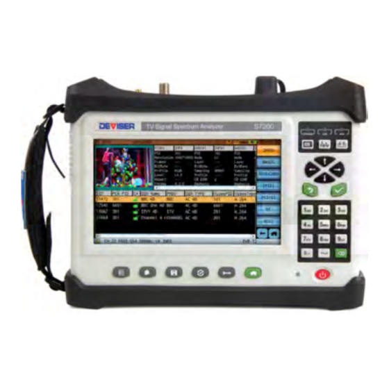
- Page 1 S7200 TV Signal Spectrum Analyzer User Guide...
-
Page 2: Table Of Contents
S7200 TV Signal Analyzer Table of Contents PART I: S7200 BASICS Safety Precautions Maintenance and Safety Considerations Calibrating the Meter Other Safety and Maintenance Tips Warranty Chapter 1: General Information 1‐1 About the S7200 TV Signal Spectrum Analyzer 1‐2 Accessories and Measurement Options 1‐3 Technical Support & Service 1‐4 Annual Service Verification 1‐5 Electrostatic Discharge Caution 1‐6 Battery C are Glossary of Acronyms Chapter 2: Instrument Overview 2‐1 Unpacking the S7200 Instrument 2‐2 Powering On the S7200 2‐3... - Page 3 S7200 TV Signal Analyzer Chapter 5: Analog Non‐Linear Distortion Tests 5‐1 CNR 5‐2 CTB / CSO Chapter 6: Digital Signal Measurements 6‐1 DVB‐C Measurement 6‐2 Digital HUM 6‐3 Constellation Diagram 6‐4 Error Vector Spectrum (EVS) Function 6‐5 ATSC (8VSB) Measurement 6‐6 DVB‐C2 Measurement 6‐7 DVB‐T/H Measurement 6‐8 DVB‐T2 Measurement 6‐9 ISDB‐T Measurement 6‐10 DVB‐S/S2 Measurement 6‐11 Antenna Edit 6‐12 Transport Stream Analysis 6‐13 IPTV Measurement 6‐14 Optical Power Measurement and Optical Receiver 6‐15...
- Page 4 S7200 TV Signal Analyzer PART IV: SYSTEM FUNCTIONS Chapter 13: System Settings 13‐1 About (System Information) 13‐2 General Settings 13‐3 Measure Settings 13‐4 External Interface Setup 13‐5 Antenna Settings 13‐6 Updating System Firmware Chapter 14: File Management 14‐1 File Operations 14‐2 Importing and Exporting Data Chapter 15: Saving Data 15‐1 Screenshots 15‐2 Measurement Data SPECIFICATIONS 4 ...
-
Page 5: Part I S7200 Basics
S7200 TV Signal Analyzer Part I S7200 Basics 5 ... -
Page 6: Safety Precautions
These precautions must be thoroughly understood, and they apply to all phases of operation and maintenance. Deviser Instruments, Inc. assumes no liability for the operator’s failure to comply with these precautions... -
Page 7: Maintenance And Safety Considerations
If power fails during the updating process, instrument function may be affected. DANGER: The S7200 contains an optional VFL (Visual Fault Locator). To avoid eye damage, never look directly into the VFL output port while the light is on, and wear appropriate eye protection when necessary. - Page 8 Part I: S7200 Basics Safety Symbols The following are general definitions of safety symbols used on equipment and in manuals. Dangerous voltage. Protective ground. Frame or chassis ground. Alternating current. Direct current. Alternating or direct current. Caution! Read the manual.
-
Page 9: Warranty
This Deviser Instruments, Inc. product is warranted against defects in material and workmanship for a period of 36 months from the date of shipment. Under warranty, Deviser Instruments, Inc. will, at its option, either repair or replace products which prove to be defective. -
Page 10: Chapter 1: General Information
The S7200 can perform TS (transport stream) analysis with the RF and ASI ports; simply record the output to a SATA SSD or USB device for easy playback. In line with recent strides in optical LNB use, optical power meter and optical receiver options are available. -
Page 11: Accessories And Measurement Options
Please contact Deviser Instruments for an RMA number and the location of the nearest Authorized Deviser Instruments service center. Our authorized service centers are skilled and certified in the calibration, service, repair, and performance verification of our products. -
Page 12: Electrostatic Discharge Caution
It is recommended to discharge the static by connecting a short or load device to the cable or antenna before connecting them to the S7200. It is important to remember that the operator may also carry a static charge that can cause damage. Following the practices outlined in the above standards will ensure a safe environment for both personnel and equipment. - Page 13 Part I: S7200 Basics 1-6.2 Charging the Unit Please follow the following steps to charge the unit: 1. Place the instrument standing up with the screen facing you, then insert the DC connector into the VDC power inlet at the top left of the instrument.
-
Page 14: Glossary Of Acronyms
Part I: S7200 Basics Glossary of Acronyms Advanced Audio Coding eMTA Embedded multimedia terminal adapter AC-3 Dolby AC-3 audio coding Electronic Program Guide ACPR Adjacent Channel Power Ratio Elementary Stream Audio Engineering Society ETSI European Telecommunications Standards Institute Advanced Encryption Standard... - Page 15 Part I: S7200 Basics NVOD Near Video On Demand Service Description Table OFDM Orthogonal frequency division multiplexing Severely errored second OFDMA Orthogonal frequency division multiple SECAM Sequential Color and Memory access Sequential Couleur avec Memoire Optical Power Meter Service Information...
-
Page 16: Chapter 2: Instrument Overview
Part I: S7200 Basics Chapter 2: Instrument Overview This chapter describes how to get started with the S7200 TV Signal Spectrum Analyzer. Topics covered in this section include: Overview of instrument panels, display, and operation Changing measurement modes and applications Unpacking the S7200 Instrument When unpacking your S7200 instrument for the first time, it is recommended that you follow these steps. -
Page 17: Front Panel Overview
Part I: S7200 Basics Front Panel Overview The S7200 TV Signal Analyzer’s front panel contains the software boot switch and a number of LED status indicator lights. It also bears the unit’s model number. LED Charge Indicator This light shows the battery charge status. When red, the battery is charging; when green, it is fully charged. -
Page 18: Top And Side Panel Overview
Conditional Access Module for channel decryption. (See subsection 6-12.12 for instructions.) USB Type-A port The S7200 has a Type-A USB 2.0 port that accepts USB storage devices for transferring measurements, setup files, screen images, GPS dongle option, and other data. LAN port The LAN port is used to network the device to a PC. -
Page 19: Control Overview
Part I: S7200 Basics Control Overview The S7200 employs a 7”, 800x480 backlit color display that is configured for ease of use and navigation. You can easily and quickly change measurement functions using the hotkeys located on the right side of the screen, above the arrow keys. -
Page 20: Measurement Main Menu
Part I: S7200 Basics Measurement Main Menu The S7200 TV Signal Analyzer provides the following spectrum analysis measurement modes, aimed at simplifying the installation, maintenance and troubleshooting of a CATV broadcasting system. (Note: some measurements are only available by option. See Section 1-2 for option info.) Measurement (TV &... -
Page 21: Set Up Your Channel Plan First
Part I: S7200 Basics Set Up Your Channel Plan First Before launching a measurement with the S7200, it is recommended to set up the channel plan you wish to use for testing. You can do this from the Channel Plan Editor (press the button below the screen). -
Page 22: Measurement Mode Selection
For instructions on using individual measurement functions, see Part 2: Settings and Measurements. About the Soft Carrying Case The S7200 can be operated while in the soft carrying case. On the back of the case is a large storage pouch for accessories and power supply. -
Page 23: Part Ii: Settings And Measurements
Part II: Settings and Measurements Part II Settings and Measurements 23 ... -
Page 24: Chapter 3: Channel Plans
The left pane lists a total of 16 user plans (up to 100 plans may be stored on one S7200) that can be individually edited. By default, they are named “usrpln00” through “usrpln15”, but can be renamed as the operator desires. - Page 25 625-line system: Field 1 (odd), line 1~313; Field 2 (even), line 2~312 NOTE: For Analog channels, you will need to instruct the S7200 where to look for “Gated” quiet line, GCR or Multiburst, CCR-7 VITS test signals, field and line location. If these changes are made during testing, said changes will not be saved for the next test.
- Page 26 Part II: Settings and Measurements Supported Analog TV Standards TV standard Lines per frame Field frequency Color encoding method NTSC-M 60Hz NTSC PAL-M 60Hz NTSC PAL-B,D,G,H,I,K 50Hz PAL-N 50Hz Digital (DVB-C, -C2, -T2, T/H) & ATSC Channel Parameters Channel serial number: Channel name: Edit with keypad Channel status:...
- Page 27 Select OK to save, or Cancel to discard changes. More channel plan templates are available in the S7200 Toolbox software. Deviser may be able to write customer-specific channel plans upon request. 27 ...
- Page 28 3-1.3 Importing and Exporting TV Channel Plans To transfer user channel plan data to and from the S7200, you will first need to insert a USB storage device into the instrument’s top panel. Once the application reads the USB device, the Export key appears. In addition, if the USB device already contains some channel plan data, Import appears.
-
Page 29: Satellite Channel Plans
Part II: Settings and Measurements Satellite Channel Plans A satellite channel plan involves both satellites and satellite transponders. New satellites are launched each year, many of them using their own modified transponder settings. There is no uniform standard; thus, users must manually enter the satellite and transponder parameters in their satellite channel plans. - Page 30 Part II: Settings and Measurements The LNB (Low Noise Block Down Converter) is composed of microwave LNA (Low Noise Amplifier) and LNC (Low Noise Converter). The LNC is itself composed of a mixer, local oscillator, and IF preamplifier. First, the LNB amplifies signals it has received in the C (3.4~4.2GHz) or Ku (10.7~12.75GHz) frequency bands. Then it uses the signal frequency, minus the local oscillator frequency in the mixer –...
- Page 31 3-2.3 Importing and Exporting Satellite Channel Plans To transfer user channel plan data to and from the S7200, you will first need to insert a USB storage device into the instrument’s top panel. Satellite channel plans can be imported and exported using the same steps as TV channel plans. See subsection 3-1.3 for instructions.
-
Page 32: Chapter 4: Analog Tv Measurements
Part II: Settings and Measurements Chapter 4: Analog TV Measurements In this chapter, we discuss the S7200’s powerful suite of TV signal measurement applications – including the Channel Measurement, Spectrum, TILT, Scan, Passive Sweep, CNR, and CTB/CSO functions. Channel Measurement In this mode, the S7200 measures the basic parameters of a channel. -
Page 33: Analog Fm
Part II: Settings and Measurements Analog FM The Analog FM measurement screen, shown below, is primarily used to measure FM radio signal levels. You can also listen to the audio output. 4-2.1 Settings Channel: The channel to measure. Select any active analog or digital channel in the active channel plan. -
Page 34: Hum Modulation
Hum is an interference type that generates harmonics following AC frequencies. This phenomenon creates a visible distortion in television signals. With the Hum Modulation function, the S7200 measures the effects of this interference on analog and digital channels. The analog measurement screen is shown below. -
Page 35: Channel Scan
Part II: Settings and Measurements Channel Scan The S7200 offers a channel scan function to quickly measure the flatness and amplitude of a CATV system (shown below). By default, the instrument scans all active analog or digital channels in the active channel plan. -
Page 36: Passive Sweep
Passive Sweep A stored passive sweep trace can be used as a reference. Up to 8 trace records can be saved to the S7200 for this purpose. This feature is primarily used when an active sweep reference generator is not in use at the HE or hub. -
Page 37: Tilt Measurement
Part II: Settings and Measurements Tilt Measurement The Tilt measurement helps to quickly measure the flatness of a CATV system and the gain of the splitters / taps. This feature provides power levels for up to 16 channels. Upon entering the Tilt function, you will be prompted to set the tilt plan. -
Page 38: Depth Of Modulation (Dom)
Part II: Settings and Measurements Depth of Modulation (DOM) From the Channel Measurement mode, tap DOM to start the Depth of Modulation function. Depth of modulation is measured as the percentage of the total amplitude change of the carrier, as the signal progresses from sync tip to peak white. -
Page 39: Auto
Part II: Settings and Measurements Auto The Auto function performs a rapid scan of all channels in the current channel plan. When activated, it reads the signal level and categorizes each channel as analog or digital. In a digital search, the Auto tool searches for DVB-C, DVB-T/H, DVB-T2, DTMB, DOCSIS, DVB-C2, ISDB-T, and ATSC in order. -
Page 40: Chapter 5: Analog Non-Linear Distortion Tests
In a gated CCN test, the S7200 will first measure peak carrier level, and then trigger on the appropriate VITS line # (preset for each channel; can be set in the channel plan editor) to measure noise. Occasionally, VITS lines are already quiet enough when video signals are delivered by the Broadcaster. - Page 41 Part II: Settings and Measurements Gated CCN Measurement – Frequency‐Domain Waveform (left) and Time‐Domain Waveform (right) To conduct a gated measurement, ensure that the video carrier frequency, noise bandwidth, TV signal standard, odd/even field, and line number are set properly in the channel plan editor. (See Section 3-2.) Then tap Gated to toggle it on. CCN gated measurements support the following TV standards: System &...
-
Page 42: Ctb / Cso
When we measure CSO and CTB, the test results are in terms of C/CSO and C/CTB. In the gated mode, the S7200 will first measure absolute carrier level, then trigger the appropriate VITS line # (preset for each channel – can be set in the channel plan editor) to measure noise. -
Page 43: Chapter 6: Digital Signal Measurements
(in select models only) Parameter Settings The S7200’s channel analysis function is fully automated, except for a few simple values such as frequency. Most parameters are acquired automatically. (They may still be manually adjusted to user preference). Adjustable parameters and range of the DVB-C function of the S7200 are as follows. -
Page 44: Dvb-C Measurement
Part II: Settings and Measurements DVB-C Measurement The digital channel measurement screen (shown below) displays basic digital metrics after demodulation. Tap the screen (or use the arrow keys) to move between parameters: channel, frequency and bandwidth. When the cursor highlights a field, you can adjust the value with the arrow keys or input your desired value with the keypad. -
Page 45: Digital Hum
Hum modulation, or power source frequency modulation distortion, comes from a power source frequency interference. HUM modulation generally degrades MER values of a digital carrier. The S7200 supports hum modulation measurements for digital channels. The measurement interface is shown below. -
Page 46: Constellation Diagram
Part II: Settings and Measurements Constellation Diagram In the constellation diagram, you can refresh and zoom the display. To zoom in, first tap Select repeatedly to place the red border over a quadrant to view. After choosing the quadrant, tap Zoom IN. The selected quadrant will expand to fully occupy the screen. -
Page 47: Error Vector Spectrum (Evs) Function
Frequently used LTE bandwidths include 5, 10, and 20MHz. These types of bandwidth are all close to or wider than the DVB-C signal bandwidth. Both LTE and DVB-C are digital signals, and are similar to noise. The S7200 uses the EVS time-domain function to display LTE sub-frames coming in every 1ms (above). 47 ... -
Page 48: Atsc (8Vsb) Measurement
In order to demodulate 8VSB signals, the user must first set up the following parameters: Pilot position: the S7200 has the unique ability to auto-set the pilot position. It can be set to the left (low) side or the right (high) side of the spectrum. - Page 49 Part II: Settings and Measurements 6-5.4 Eye Diagram Another way to determine the signal quality is with the eye diagram. Look for the seven “eyes” down the center of the display, formed by intercrossing lines. If some eyes are not fully “open”, the signal is not clear enough.
-
Page 50: Dvb-C2 Measurement
Part II: Settings and Measurements The S7200-ATSC supports 8-VSB Simple Emission Limits with pass-fail testing (shown below). If the signal does not meet the “Simple” emissions mask requirements, an audio alarm will sound and the message “FAILED” will appear in red. (Tap Mute to stop the alarm.) Spectrum Mask Test – Pass ... -
Page 51: Dvb-T/H Measurement
All other parameters will be auto-set according to the pilot and TPS carrier. (Note: DVB-H 4k carrier mode is not supported.) If the above settings are in place and a clear signal is received, the S7200 can correctly demodulate 8VSB. - Page 52 Part II: Settings and Measurements 6-7.4 Constellation Diagram The DVB-T/H constellation function features two display modes: single-carrier, multi-carrier, and hierarchical modulation constellation. Multi-carrier (right) is the default mode. Tap Carrier to select a different carrier number from the dropdown box. If a carrier number is followed by “DATA”, that carrier is used for data transmission;...
- Page 53 Part II: Settings and Measurements DVB-T/H Echo Pattern Post-echo: In this scenario, the strongest path (main path) leads from the nearest transmitter tower, and the other paths are either from transmitters located further away or from reflections which arrive after the main path and have lower power levels.
-
Page 54: Dvb-T2 Measurement
DVB-T2 standard (published by ETSI in 2012 [EN 302 755 v.1.3]). The S7200 supports the DVB-T2 signal test in EN 302 755 v1.1.1, v1.2.1 and v1.3.1. A variety of measurement functions are available: average power, MER, CBER, VBER, constellation test, echo pattern, and L1 and PLP information. - Page 55 Part II: Settings and Measurements 6-8.4 Constellation Diagram New to DVB-T2, rotated constellations help improve system performance in fading scenarios by means of signal-space diversity. Here, rotation is applied to the constellation symbols so that the 2 components in the imaginary plane –...
- Page 56 Part II: Settings and Measurements The S7200 measures DVB-T2 rotated constellation, as shown below. This constellation is only for PLP content. If the DVB-T2 signal includes multiple PLPs, tap PLP ID to select one. Changing the PLP will also affect the constellation display (if each PLP has a different modulation type).
-
Page 57: Isdb-T
200kHz each for the upper and lower adjacent channels. One sub- band of the ISDB-T channel has a width of 430kHz. Note: The ISDB-T measurement is only available on model S7200-ISDB. See Section 1-1 for details. It is possible to select different types of modulation in ISDB-T: ... -
Page 58: Dvb-S/S2 Measurement
Depending on the selected satellite channel plan, you can launch the Measure mode to view measurement results for a transponder on the current satellite. The S7200 supports DVB-S (below, left) and DVB-S2 (below, right) signal demodulation. For DVB-S2, only QPSK and 8PSK demodulation are supported. 6-10.1 Settings Transponder name. -
Page 59: Antenna Edit
Once you have selected a satellite and transponder, set up the LNB power supply according to satellite parameters and local antenna conditions. Installation technicians will need to know the following: Antenna GPS location (right). The S7200 offers a GPS module, allowing users to auto-acquire coordinates; or you can manually input the longitude / latitude (see below). - Page 60 Part II: Settings and Measurements Once you select a satellite and determine the local coordinates, the unit can auto-calculate the azimuth, elevation, and LNB polarization angles. Each transponder test result uses a different color display based on preset thresholds (limits). Tap THRESHOLD to open the threshold setup dialog (below). First, consider the elevation angle.
- Page 61 Part II: Settings and Measurements In the application, tap FIX to halt the transponder scan. Tap MEASURE to enter the measurement interface. During a transponder scan, a failed test will activate an audio alarm. Tap Mute to silence the alarm. Finally, tap DRIVE to open a polar antenna control window (below).
-
Page 62: Transport Stream Analysis
Part II: Settings and Measurements 6-12 Transport Stream Analysis The TS analysis function supports DVB and ATSC standard real-time TS analysis. Measurements include Basic Information, TR 101 290 Priority 1, 2 and 3 Tests, PID Viewer, PCR Analysis, Program List, and Data Capture. Supported Standards: MPEG-1 1) ISO-IEC-11172-2(Video) - Page 63 Part II: Settings and Measurements The S7200 displays a real-time picture feed in the upper-left corner of the screen. Drag the slide control under the picture to adjust audio volume. If the program signal is encrypted, the picture feed may not be immediately available;...
- Page 64 Priority 1 - no decidability Priority 2- partially no decidability Priority 3- errors in the supplementary information/SI Due to hardware resource limits, the S7200’s TS analysis does not include buffer-test-related parameters. Priority 1 Parameters (1) TS_sync_loss: It is suggested that five consecutive correct sync bytes are sufficient for sync acquisition, and two or more consecutive corrupted sync bytes indicate a sync loss.
- Page 65 Part II: Settings and Measurements (4) Continuity_count_error: Each transport stream packet contains a 4-byte-long header, a 4-bit counter which counts from 0 to 15 in a loop, and then begins at zero again after an overflow (modulo 16 counter). However, each transport stream packet for each PID has its own continuity counter, i.e. packets with a PID=100, e.g., have a different counter, as do packets with a PID=200.
- Page 66 Part II: Settings and Measurements Priority 2 Parameters (1) Transport_error: Every MPEG-2 transport stream packet contains a bit called Transport Error Indicator which is transmitted right after the sync byte. This bit flags any errors in the transport stream packets at the receiver.
- Page 67 Part II: Settings and Measurements Priority 3 Parameters (1) NIT_actual_error: Network Information Tables (NIT) as defined by DVB, contain information on frequency, code rates, modulation, polarization, etc. of various programs which the decoder can use. It is checked whether the NIT related to the respective TS is present in this TS and whether it has the correct PID. (2) NIT_other_error: Further NITs may be present under a separate PID and refer to other TSs to provide more information on programs available on other channels.
- Page 68 Part II: Settings and Measurements 6-12.4 PID Viewer Lists the summary, value(%), PID, and CR of every PID in the stream. Section: The PID type, e.g., PSI/SI, video PID or Audio PID. PID: The PID value. The bitrate of the PID. The Value and CR are calculated in one-second increments.
- Page 69 Part II: Settings and Measurements 6-12.6 Program List Lists all programs in the current transport network by ascending frequency. Info includes program number, frequency, SID, service name, CA, provider, and service type. Depending on the encoding method, the program information may be displayed differently; you might see the program information of the selected frequency, or the program information of all frequencies.
- Page 70 Part II: Settings and Measurements 7200 PSI/SI analysis includes PAT, PMT, CAT, NIT Actual, SDT Actual, EIT Actual, and TDT. (See below.) The following screenshots highlight more detailed analysis information. Tap the screen to choose a table, then tap the “+” symbol to expand into multiple levels. PSI/SI Analysis –PAT ...
- Page 71 Part II: Settings and Measurements Service Information Allocation PID & Table ID of PSI/SI Tables Table Table_ID PID Decimalism Table PID Value Value 0x0000 0x00 0x0020… 0x1FFE 0x02 0x0000 0x0001 0x01 0x0001 0x0010 0x40…0x41 TSTD 0x0002 0x0011 0x4A 0x0010 0x0011 0x42, 0x46 SDT, BAT, ST 0x0011...
- Page 72 Part II: Settings and Measurements 6-12.8 PSI/PSIP Table Analysis Like the SI tables, DVB & ATSC also provide PSIP tables. PSIP stands for "program and system information protocol" and lists info similar to that given on DVB SI. In ATSC, the following tables are used: the Master Guide Table (MGT), the Event Information Table (EIT), the Extended Text Table (ETT), the System Time Table (STT), the Rating Region Table (RRT), and the Cable Virtual Channel Table (CVCT) or the Terrestrial Virtual Channel Table (TVCT).
- Page 73 Part II: Settings and Measurements ATSC PSIP tables (top‐left); Extended Text Tables (ETTs) defined to carry text to describe virtual channels/events (bottom‐left); PSIP table hierarchy (right) PSI/PSIP Analysis –PAT PSI/PSIP Analysis – PMT PSI/PSIP Analysis –MGT PSI/PSIP Analysis – VCT 73 ...
- Page 74 Part II: Settings and Measurements PSI/PSIP Analysis –EIT PSI/PSIP Analysis – ETT PSI/PSIP Analysis ‐ STT 6-12.9 Data Capture The image above shows captured transport package data according to PID value. This function divides the PID into six types: video, audio, PCR, PSI/SI, ECM/EMM and DATA. Choose a type and press Enter to confirm; the related PID value will display in PID position.
- Page 75 Record and Replay Transport Stream Recording the Transport Stream The S7200 can be used to record transport stream data to a solid-state drive (if the SATA SSD option has been purchased) or to a storage drive connected to the unit’s USB port.
- Page 76 Part II: Settings and Measurements Record Playback When you have recorded the transport stream successfully, you can use the S7200 to review the recording. Press the button and tap the top key repeatedly until TS is displayed. (Note that only files saved to the SSD, not to a separate USB drive, are shown here.)
- Page 77 6-12.12 Using the Conditional Access Module With the appropriate decryption card inserted, the S7200 can be used to decode encrypted programs. When the CAM module and smart card have been correctly installed in the DVB-CI port, the CAM icons ) will appear in the top status bar. However, even if the hardware is installed, successful decryption is not guaranteed.
- Page 78 In the key edit dialog, you can select Default Key, Add Service, Service ID, and Empty All Services. If there is no existing Service ID, you will need to add one. Tap Add Service; the S7200 will auto-recognize the correct Service ID. You may then choose whether to Modify Key or Delete Service. To modify, select either Mode-1 or Mode-E;...
-
Page 79: Iptv Measurement
Part II: Settings and Measurements 6-13 IPTV Measurement Currently, the S7200’s IPTV function only supports MPEG-2 TS over IP. First, connect an Ethernet cable to the S7200’s RJ-45 port. From the Home screen, tap IPTV to launch the IPTV function. -
Page 80: Optical Power Measurement And Optical Receiver
Straight air gap connectors (e.g. ST connectors), are used for multimode fibers. FC Connector SC Connector ST F Connector The S7200 uses the FC/SC/ST replaceable universal connector interface. Users may replace these with different connector interfaces as needed for field applications. 80 ... - Page 81 Replaceable FC/SC/ST universal connector interface 6-14.3 Optical Power Measurement The S7200 also features an optical power meter (OPM). (The optical receiver option is required; but you do not need to activate “Óptic to RF”.) Simply connect an optical fiber to the FC/APC port. The unit will auto-detect the wavelength of the incoming signal.
- Page 82 Example: displayed test result = 10 + (-1) = 9dBm. First, perform a power cycle by turning the S7200 off and on again. Return to the OPM function. Tap COMPENS, and tap the Offset field for the relevant wavelength signal. Type a value and press Enter to confirm.
- Page 83 Part II: Settings and Measurements dBm mW 30.0 1W 1000 20.0 100mW 100 10.0 10mW 10 7.0 5mW 5 0.0 1mW 1 ‐3.0 500μW 0.5 ‐10.0 100μW 0.1 ‐20.0 10μW 0.01 ‐30.0 1μW 0.001 ‐40.0 100nW 0.0001 Conversion Table: common dBm values vs mW 83 ...
-
Page 84: Downstream Spectrum Analysis
17. Frequency and level of marker B 18. Delta variation between marker A and B (in frequency and level) 19. Active trace: up to 4 traces can appear at once on the S7200. Only 1 trace is controlled at a time. 20. Test Point Compensation. (TP) 21. - Page 85 Part II: Settings and Measurements Note that you can adjust the frequency, span, reference level, and marker position using the touchscreen. Using one finger, drag left or right on the screen to explore different sections of the frequency spectrum. Drag up or down to shift the reference level accordingly. Note that touching the markers (green or blue horizontal/vertical lines) will allow you to move the markers.
- Page 86 Part II: Settings and Measurements 6-15.2 Frequency and Span Settings (CENT, START, STOP, SPAN) Tap FREQ to enter the frequency menu. From here, tap the keys along the right to access various submenus (shown below). Some parameters, such as the center frequency (4-1220 MHz), can be manually entered with the numerical keypad or adjusted with the arrow keys.
- Page 87 Tap BW/SWP to enter the menu (shown, right), and then RBW or VBW as desired. Select Auto to allow the S7200 to choose a suitable bandwidth according to sweep speed and span settings, or Manual to...
- Page 88 In the bandwidth menu, tap Sweep. Select Auto to allow the S7200 to choose a suitable sweep time according to the active Span, VBW, and RBW settings; or Manual to enter a new value. Press Enter to confirm.
- Page 89 Part II: Settings and Measurements 6-15.5 Markers The spectrum analysis measurement has two markers, A and B, displayed on the trace as color-coded vertical lines. Their current frequency and amplitudes are shown below the trace. (See above.) Touch a marker and slide it left or right to adjust the frequency. Tap Mark to enter the marker menu.
- Page 90 6-15.6 Trace Setting The S7200 can display up to 4 color-coded traces at once, each coded to a different trace calculation method: normal (“write”), maximum hold, minimum hold, and average. Tap Trace to open the trace menu. Here, repeatedly tap the [Trace #] key at the top of the submenu to cycle through the traces numbered 1- 4.
- Page 91 Print Mode New to the S7200 is Print mode. By inverting the screen colors from dark background and a light trace color to a light background and a dark trace color, printing hard copies of saved traces is more cost-efficient.
-
Page 92: Wifi Analysis
The WiFi analysis mode is primarily used to display the surrounding WiFi channels, their SSID, their designated channel within the WiFi band used, and their relative amplitude level from the S7200 location. (See the figuresError! Reference source not found. below for the graphical interface.) The WiFi Analysis function has two display modes: graphical and list. -
Page 93: Dtmb Measurement
Part II: Settings and Measurements 6-17 DTMB Measurement The DTMB (Digital Terrestrial Multimedia Broadcast, the TV standard for mobile and fixed terminals used in China, Cuba, Hong Kong, and Macau) measurement function allows users to read signal power, CNR, MER, LM, BER, constellation, and other data. - Page 94 Part II: Settings and Measurements 6-17.2 Signal Shoulder Test When the digital TV signal is amplified, the intermodulation output outside the channel is an approximate continuous spectrum. The continuous spectrum outside the channel generates “shoulder” effects, called the band shoulder. The “shoulder ratio” is the ratio of the power level at the center frequency to that of a single point deviating from the center frequency outside the carrier.
-
Page 95: Dab/Dab+ Measurement
167.392 ~ 239.968 MHz – accurate to the nearest kHz. DAB measurement When the signal is locked, the S7200 will automatically search for all programs, sub-channel ID, DAB type, and encryption data of the selected channel. If audio issues are detected, tap Listen to activate the audio feed. -
Page 96: Part Iii: Background And Concepts
Part III: Background and Concepts Part III Background and Concepts 96 ... -
Page 97: Chapter 7: Analog Tv Standards & Color Systems
Part III: Background and Concepts Unit Conversion Chart Unit Impedance 50Ω Impedance 75Ω μV 1μV=10-6V 1μV=10-6V 1mV=1000μV 1mV=1000μV dBμV 0dBμV=1μV 0dBμV=1μV dBmV 0dBmV=1mV 0dBmV=1mV 0dBm=107dBμV 0dBm=108.8dBμV Chapter 7: Analog TV Standards & Color Systems There are many different TV standards in use around the world, defining in detail the acceptable baseband and RF structure of a signal. - Page 98 Part III: Background and Concepts Reference for the Following Diagrams: Audio carrier Video carrier Color subcarrier VSB: Vestigial Sideband USB: Upper Sideband TV Standard ‐ M, N TV Standard ‐ B, G TV Standard ‐ D, K TV Standard ‐ H TV Standard – I TV Standard ‐ K1, L 98 ...
- Page 99 Part III: Background and Concepts Color system parameter setup for various TV standards TV Standard Lines per frame Field frequency Color encoding Color subcarrier NTSC-M 60Hz NTSC 3.58MHz PAL-M 60Hz NTSC 3.58MHz PAL-B,D,G,H,I 50Hz 4.43MHz PAL-N 50Hz 4.43MHz PAL-N combo 50Hz 3.58MHz 4.406MHz...
-
Page 100: Chapter 8: Analog Tv Baseband Signals
Part III: Background and Concepts Chapter 8: Analog TV Baseband Signals Understanding Composite Video Signal A composite video signal is a signal containing all three main components required to generate video. These components are: The luminance signal contains the intensity (brightness) information of the video image. ... - Page 101 Part III: Background and Concepts The synchronization signals in an analog composite baseband To reproduce an image, both the camera and the video display are scanned horizontally and vertically (see graph a in the above figure). The horizontal lines on the screen are scanned alternately – first the odd- numbered lines, then the even –...
-
Page 102: Principles Of Interlaced Scanning
Part III: Background and Concepts The active video image resulting from the scanning always has an aspect ratio (horizontal/vertical) of 4/3, regardless of the video format. The color composite video signal shows that the scanning process requires some additional room on the left and right sides of each line, as well as on the top and bottom, of the active video image region. -
Page 103: Principles Of Gated Measurements
Part III: Background and Concepts Principles of Gated Measurements Field A television image, or frame, is composed of 525 (or 625 lines). When displayed, these are delivered in two successive fields of 262.5 (or 312.5 lines) interlaced together on a CRT. When Field is set to Entire Frame, the line count starts at line one in field one (often referred to as the “odd field”) and ends at 525 (or 625) in field two (often referred to as the “even field”). - Page 104 (at the specified field). The S7200 first measures the video carrier peak level during the sync pulse. Then, while the quiet line inserter removes a specified line at the same time in every frame, the instrument uses the gated function to measure third order beat.
- Page 105 Part III: Background and Concepts 8-3.2 Video Parameters Gated Measurement VITS (Vertical Interval Test Signal) In the past, engineers often used full-field test signal to test TV systems. This particular test process requires the field or HE engineer to interrupt the specific channels from broadcasting. In today’s HFC networks, for competitive and other reasons, this is no longer a feasible plan.
- Page 106 Part III: Background and Concepts CCIR Line 18(multiburst) CCIR 18 test signal CCIR 18, also called a multiburst signal, consists of a set of single frequency sine wave signals with equal amplitude. The left side is a white flag with a peak amplitude 420mVp-p and provide amplitude standard for the following multiburst signals.
- Page 107 Part III: Background and Concepts CCIR 330 test signal The first peak from the left is a white flag with peak amplitude of 700mV (relative to blanking level) and a width of 10µs; a zero carrier reference (base white) for measuring video signal amplitude and depth of modulation.
- Page 108 Part III: Background and Concepts Applications of VITS Signals Measurement Parameter VITS Signal A brief waveform distortion 2T pulse (CCIR 17) 10T pulse is made up of a sine-squared luminance CLDI pulse and a chrominance packet with a sine-squared envelope (CCIR 17) Chrominance nonlinear distortion Three-level chrominance bar (CCIR 331) Overshoot distortion...
-
Page 109: Chapter 9: Satellites And Transponders
This chapter will provide a basic overview of satellite transmission concepts, related to designing a satellite channel plan. For instructions on creating a satellite channel plan on the S7200, see Section 3-2. A satellite channel plan is composed of satellites and satellite transponders. A transponder is a device that receives signals transmitted from ground stations on Earth, amplifies them, and transmits them back down to the desired receiver . -
Page 110: Polarization And Lnb
Part III: Background and Concepts Polarization and LNB Satellite signals have two types of polarization: circular and linear. Circular polarization can be divided into right-handed (or clockwise) and left-handed (or counterclockwise); while linear polarization can be divided into horizontal and vertical. Most satellites use the horizontal and vertical polarization transmission signals. Today, many new products combine the LNB and Feedhorn into one: LNBF (LNB with Feedhorn). - Page 111 Part III: Background and Concepts Some manufacturers provide double local oscillators for Ku band LNB. With two sets of circuits and local oscillators for different polarizations (9.75GHz and 10.6GHz are commonly-used), users can use a 0/22kHz impulse signal to control low-frequency and high-frequency band LO. Ku‐band low and high frequencies ...
-
Page 112: Satcr Overview
Part III: Background and Concepts SaTCR Overview Unicable LNBs (see below) receive Ku-band satellite signals the same way that traditional LNBs do. The difference is the addition of SCR and MCU chips. When the receiver’s low-noise amplifier receives satellite signals, they may be of four different frequency bands: low- and high-LO vertical polarization (V/L and V/H), and low- and high-LO horizontal polarization (H/L and H/H). -
Page 113: Chapter 10: Resolution And Video Bandwidth
The S7200 offers automatic or manual RBW selection depending on frequency/span/sweep time selection and/or what the user is looking for. The S7200 uses digital IF and leverages DSP (Digital Signal Processing) techniques of implementation, so the digital filters won’t drift as analog filters would in older spectrum analyzers. -
Page 114: Chapter 11: Detector Mode
Part III: Background and Concepts Chapter 11: Detector Mode When measuring and analyzing different types of signals with a spectrum analyzer, the detector mode should be set correctly. “Pixel point” is an important concept related to the detector mode of a spectrum analyzer. -
Page 115: Chapter 12: International Catv Standards
Part III: Background and Concepts Chapter 12: International CATV Standards System and Standards by Country Country System Standard Country System Standard Afghanistan El Salvador NTSC Albania Equatorial Guinea Algeria Estonia Argentina Ethiopia Angola Finland Australia France SECAM Antigua & Barbuda NTSC French Guiana SECAM... - Page 116 Part III: Background and Concepts Mexico NTSC Sudan Monaco SECAM Surinam NTSC Mongolia SECAM Swaziland Montenegro Sweden Morocco SECAM Switzerland Mozambique Syria SECAM Nepal Tahiti SECAM Netherlands Taiwan NTSC New Zealand Tanzania Nicaragua NTSC Thailand Niger SECAM Tonga NTSC Nigeria Trinidad y Tobago NTSC Norway...
- Page 117 Part III: Background and Concepts Common CATV Channel Plans: North America EIA channel Standard Incremental Harmonic Video Audio Video Audio Video Audio none 7.0000 11.5000 none 13.0000 17.5000 none 19.0000 23.5000 none 25.0000 29.5000 none 31.0000 35.5000 none 37.0000 41.5000 none 43.0000 47.5000 55.2500 59.7500...
- Page 118 Part III: Background and Concepts 319.2625 323.7625 319.2625 323.7625 318.0159 322.5159 325.2625 329.7625 325.2625 329.7625 324.0162 328.5162 331.2750 335.7750 331.2750 335.7750 330.0165 334.5165 337.2625 341.7625 337.2625 341.7625 336.0168 340.5168 343.2625 347.7625 343.2625 347.7625 342.0171 346.5171 349.2625 353.7625 349.2625 353.7625 348.0174 352.5174 355.2625 359.7625 355.2625 359.7625 354.0177 358.5177...
- Page 119 Part III: Background and Concepts 655.2500 659.7500 655.2625 659.7625 654.0327 658.5327 661.2500 665.7500 661.2625 665.7625 660.0330 664.5330 667.2500 671.7500 667.2625 671.7625 666.0333 670.5333 673.2500 677.7500 673.2625 677.7625 672.0336 676.5336 679.2500 683.7500 679.2625 683.7625 678.0339 682.5339 685.2500 689.7500 685.2625 689.7625 684.0342 688.5342 691.2500 695.7500 691.2625 695.7625 690.0345 694.5345...
- Page 120 Part III: Background and Concepts Common CATV Channel Plans: People's Republic of China (PAL; standard D/K) Channel Bandwidth: 8MHz Ch. No. Video Audio Ch. No. Video Audio 49.75 56.25 DS13 471.25 477.75 57.75 64.25 DS14 479.25 485.75 65.75 72.25 DS15 487.25 493.75 77.25...
- Page 121 Part III: Background and Concepts Common CATV Channel Plans: Europe (PAL; standard B/G) Channel Bandwidth: 7 and 8 MHz Ch.No. Video Audio Ch.No Video Audio 7MHz channel spacing 8MHz channel spacing 48.25 53.75 303.25 308.75 55.25 60.75 311.25 316.75 62.25 67.75 319.25 324.75...
- Page 122 Part III: Background and Concepts 687.25 692.75 823.25 828.75 695.25 700.75 831.25 836.75 703.25 708.75 839.25 844.75 711.25 716.75 847.25 852.75 719.25 724.75 855.25 860.75 Common CATV Channel Plans:- United Kingdom (PAL; ITU-R standard I) Channel Bandwidth: 8 MHz Video Audio Video Audio...
-
Page 123: Part Iv: System Functions
Part IV: System Functions Part IV System Functions 123 ... -
Page 124: Chapter 13: System Settings
Chapter 13: System Settings This chapter provides instructions for S7200 system settings and features. To access the settings menu, press the button along the bottom of the screen; then under the brightness and volume controls, tap More. There are three main settings tabs: About, General, and Measure. -
Page 125: General Settings
In Network Settings, the default connection is through the Ethernet port on the connector panel. Uncheck the Wifi box and plug in an Ethernet cable from an active network to the S7200. Set up the static IP information to connect. - Page 126 Part IV: System Functions 13-2.2 Ping The PING tool is a practical way to verify your network connectivity status and speed. In the URL field at the top, input the network or IP address to be tested (e.g., www.bing.com or 192.168.1.1). Then tap START to begin the network test.
- Page 127 Disk Management In this tab, you can check the current data usage on the S7200’s local hard drive, a SATA SSD (if installed), and/or a connected USB storage device. To format a drive, use the Up/Down keys to highlight Local or SATA and tap Format.
-
Page 128: Measure Settings
13-3.3 Adaptive Equalizer The S7200 offers two adaptive equalizer settings: Long EQ and Short EQ. Long EQ suppresses ISI (Inter-Symbol Interference) and co-frequency interference more effectively. Short EQ enables better selective filtering, and provide better performance in fully-loaded CATV plants. - Page 129 Part IV: System Functions 13-3.4 Transport Stream Settings The TS analysis function supports DVB and ATSC standards. For different regional settings, select DVB or ATSC according to local standards. The DVB setting displays PSI/SI analysis, while ATSC displays PSI/PSIP analysis (below, right).
- Page 130 Incorrect encoding will cause the parser program to garble the information. Use the “Auto Detect” tool to automatically recognize the proper encoding setting. The S7200 supports the fellow character encoding options: Auto Detect Romanian (ISO 8859-16) West European (ISO 8859-15)
- Page 131 Part IV: System Functions 13-3.5 TS Limit Settings In this menu, you can modify the limit profile for TR 101 290 Priority 1, 2 and 3 test parameters. This dictates limit alerts for the transport stream analysis function. Reference values for some parameters appear in the table below. For more setup help, see Section 6-12.3. PSI/SI Table Repetition Time Max.
-
Page 132: External Interface Setup
You can access an additional settings menu by pressing the button, under the “ASI” indicator light on the S7200’s front panel. This menu contains settings for various measurements and options, and its contents differ between TV and satellite mode. This menu contains the following tabs: In TV mode: LNB Power, Optical/RF, and TS Input/ASI Output. - Page 133 DiSEqC (Digital Satellite Equipment Control) technology. Today, several versions of DiSEqC exist. All versions are backwards-compatible. The S7200 supports DiSEqC versions 1.0, 1.1, 1.2, and 2.x. The DiSEqC menu is a scrolling list of LNB commands. Tap a command to transmit it. (If an error occurs, make sure that “LNB Power”...
- Page 134 Part IV: System Functions DiSEqC Version Guide Version Directivity Description Basic DiSEqC instruction set. Includes Tone Burst function and four LNB controls. Can transmit various commands: polarization, high & low bands, antenna position, etc. Unidirectional system, meaning that the receiver sends instructions to the corresponding system module.
- Page 135 – in this case, an LNB based on the SaTCR standard. (For background information on SaTCR, see Section 9-3.) The S7200 supports SatCR/SCR (EN50494) and dCSS/SCR2 (EN50607). SatCR and dCSS offer different equipment control and configuration settings.
- Page 136 EN50494 (SATCR, UNICABLE) and EN50607 (dCSS, JESS, UNICABLE II) standard protocols. Using the dCSS function, the S7200 supports channel controls for up to 32 users. Users can set up channels and install equipment. For the first use, in the dCSS tab, select Install to automatically search for compatible channels.
- Page 137 Part IV: System Functions 13-4.5 ASI Input/Output The ASI input/output ports are located on the S7200’s connector panel. When the ASI input status is marked valid, the icon appears in the status bar. To validate the ASI input port, set the transport stream input to ASI. Selecting DISK or IPTV will mark the output port invalid and the port will not output signal.
- Page 138 Part IV: System Functions 13-4.6 Transport Stream Input In this menu, you can select a transport stream input type: RF, ASI, DISK, or IPTV. RF Input Cable, terrestrial, and satellite signals from the RF input port. The transport stream is demodulated from the RF signal, then enters the TS analysis module.
- Page 139 Meanwhile, the S7200 can receive an external CVBS signal via the audio jack. When the external CVBS input is open, the video feed will be displayed in full-screen mode. Exit the feed by pressing Enter.
-
Page 140: Antenna Settings
Tap the topmost submenu key [FM/DAB/DTMB] repeatedly to cycle through antennas of different types. For example, to see DAB antenna files saved to the S7200, tap until [DAB] appears. Tap an antenna file from the left pane to select it. An asterisk (*) will mark the selected antenna. - Page 141 USB icon will appear in the status bar. In the antenna settings menu, tap Export to open a new dialog. On the left are the contents of the USB device, and on the right, the S7200 hard drive. Select/check files on the right, then tap the <<<...
-
Page 142: Updating System Firmware
13-6 Updating System Firmware The S7200 receives periodic updates to improve device function. To check if your device currently has the latest firmware, please contact Deviser Instruments. To install a firmware update, follow these instructions. You will need a standard USB storage/flash drive. -
Page 143: Chapter 14: File Management
Part IV: System Functions Chapter 14: File Management The ability to save and manipulate data is a key feature of using the S7200 TV Signal Analyzer. From the File Management utility – accessible by pressing the File ( ) key under the display – you can delete, view, move, and sort data files saved to the system’s internal hard drive. -
Page 144: Importing And Exporting Data
14-1.4 Delete When you no longer need one or more files, you can erase them from the S7200’s internal hard drive. Highlight files with the arrow keys and press Enter to select them. Delete will become available. When you press Delete, you will be prompted to confirm the deletion. Press OK to erase the data, or Cancel to go back. -
Page 145: Chapter 15: Saving Data
Part IV: System Functions Chapter 15: Saving Data The ability to save and manipulate data is a key feature of using the S7200 TV Signal Analyzer. From the Save dialog– accessible by pressing the Save ( ) key under the display – you can create screenshots of the current display, record detailed tables of measurement data, or generate printable work orders with the click of a button. -
Page 146: Specifications
‐30 ~ +50dBmV Modulation Type QPSK, 16 QAM, 64 QAM, 256 QAM Power Level Accuracy ±1.5dB (C/N >20dB) Power Level Range ‐35 ~ +50dBmV Guard Interval 1/64, 1/128 Level Resolution 0.1dB Bandwidth 6 MHz and 8 Mhz Power Level Accuracy ±1.5dB (C/N >20dB) Spectrum Inversion Auto MER Measurement >38dB PLP Code Rates 2/3, 3/4, 4/5, 5/6, 8/9, 9/10 MER Accuracy ±2.0dB PLP Constellation 16, 64, 256, 1024, 4096 QAM Data Slices Support type 1 & 2, up to 7.61 MHz Cell / Network / CS System ID Detected from Transmitter Station J.83 Annex B only available on model S7200-ATSC. 146 ... - Page 147 S7200 TV Signal Analyzer DVB‐S/S2 Video/Audio Decoder Modulation Type QPSK, 8PSK Video MPEG 2/4, H.264, H.256, VC‐1, AVS(+) 2 ~ 45 MS/s (DVB‐S) Video Resolution 4K, 1080p, 720p, 576i 1 ~ 45 MS/s (QPSK DVB‐S2) Audio MPEG 1/2/4, AAC Symbol Rate 1 ~ 45 MS/s (8 PSK DVB‐S2) CAM Module EN50221 (DVB‐CI) PCMCIA interface 1 ~ 45 MS/s (16 APSK DVB‐S2) WiFi Analysis 1 ~ 38 MS/s (32 APSK DVB‐S2) Frequency 2.4G, 5G Power Level Range ‐20 ~ +50dBmV Standard 802.11 a/b/g/n Level Resolution 0.1dB Security Mode WPA/WPA2/WPA‐PSK/WPA2‐PSK Power Level Accuracy ±1.5dB (C/N>20dB) Encryption WEP/AES/TKIP MER Measurement >25dB Test Parameters ...
- Page 148 7” TFT LCD 800x480 touchscreen AC: 100 ~ 240V/50‐60Hz AC/DC Adapter DC: 12V/5A Battery Li‐ion, 7.4V/13Ah Charge Time ~5 hrs. Working Time >5 hrs. Remote Feeding 5/13/15/18/24V, 5W max 22kHz control signals DiSEqC 1.2 & SaTCR 253mm x 194mm x 84mm Dimensions (WxHxL) (10.0” x 7.6” x 3.3”) Weight ~2.4kg (5.3 lbs) Operating Temperature ‐10 ~ +50°C For a list of S7200-compatible accessories and software-enabled measurement options available from Deviser, please see Section 1-2. 148 ...
- Page 149 Version 180416. ©2018 Deviser Instruments Incorporated. 780 Montague Expressway, Suite 701, San Jose, CA 95131. info@deviserinstruments.com • +1.408.955.0938 • www.deviserinstruments.com...
Need help?
Do you have a question about the S7200 and is the answer not in the manual?
Questions and answers