
Related Manuals for Deviser S7000 Series


Summary of Contents for Deviser S7000 Series
- Page 1 S7000 Series TV Analyzer Operation Manual Version 1.3 © TianJin Deviser Electronics Instrument Co., Ltd.
- Page 2 S7000 TV Analyzer Operation Manual All rights reserved. Printed in CHINA.
-
Page 3: Table Of Contents
S7000 Series TV Analyzer Operation Manual Contents 1. The Basics ................................1 1.1 General Information ............................2 1.1.1 Helpful Website ............................2 1.1.2 Warranty and Service ..........................2 1.1.3 How the manual is organized ......................... 2 1.1.4 ESC(Electrostatic Discharge) ........................3 1.2 Getting Started .............................. - Page 4 S7000 Series TV Analyzer Operation Manual 59.2 Channel Scan ..............................87 59.2.1 Parameters ............................87 59.2.2 Operation ............................. 87 59.3 Tilt measurement ............................89 59.3.1 Operation ............................. 89 59.4 CNR ................................93 59.4.1 Parameters ............................93 59.4.2 Operation ............................. 93 59.5 HUM---ANALOG TV ..........................
- Page 5 S7000 Series TV Analyzer Operation Manual 64. Operation ..............................137 65. TS Monitor & Analysis ............................139 65.1 Brief introduction ..........................140 65.1.1 Application range ..........................140 65.1.2 Standards ............................140 65.2 RealTime Decoder .......................... 141 65.2.1 Description ............................142 65.2.2 Operation ............................
- Page 6 S7000 Series TV Analyzer Operation Manual 65.13.1 Description ............................160 65.13.2 Operation ............................161 65.14 Parameter Setting ..........................162 65.14.1 Description ............................162 66. IPTV ................................... 163 66.1 IPTV ................................164 67. File Management .............................. 166 67.1 Picture File ..............................167 67.1.1 Operation ............................
-
Page 7: The Basics
S7000 Series TV Analyzer Operation Manual 1. The Basics ● General Information ● Getting started ● Getting to know S7000... -
Page 8: General Information
Deviser shall have no responsibility for any defect or damage caused by improper use and maintenance or for any product which has been repaired or altered by any one other s not DEVISER or our authorized service center. -
Page 9: Esc(Electrostatic Discharge)
S7000 Series TV Analyzer Operation Manual Section 2: Setup- provides S7000 system information, measurement setup and channel setup. Section 3: Cable&Terrestrial Signal Test- provides introduction of testing function in cable and terrestrial system. Section 4: Satellite Signal Test- provides introduction of testing function in satellite system. -
Page 10: Getting Started
S7000 Series TV Analyzer Operation Manual 1.2 Getting Started 1.2.1 Overview S7000 is a versatile TV analyzer which supports DVB-C/S/S2/T/T2 standard digital TV analysis, MPEG1/2/4, H.264 Video Record, TS analysis and spectrum analysis. 1.2.2 Shipping Inspection After removing the instrument from its packaging, perform the following steps: Take the instrument out of the case to ensure that no damage occurred during shipment. -
Page 11: Getting To Know S7000
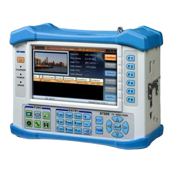
S7000 Series TV Analyzer Operation Manual 1.3 Getting to know S7000 1.3.1 Front Panel 7 8 9 6 15 13 12 Figure 1-1 TFT LCD: 7”, Resolution: 800×480. 1.3.1.1 Indicator External DC charger operation indicator. Power ON/OFF indicator. External instruments power supply indicator. - Page 12 S7000 Series TV Analyzer Operation Manual SETUP key, this key is used to enter into system setup from home menu and related setup menu in different function display. SAVE key, this key is used to save picture and data file.
- Page 13 S7000 Series TV Analyzer Operation Manual d. LNB power supply indicator. It indicates that the instrument runs LNB power when this icon appears on the title bar. Please see Section 2: SETUP->INTF.->LNB POWER to get the operation. e. GPS indicator. It indicates that the instrument recognize GPS module successfully when this icon appears on the title bar.
-
Page 14: Left Panel
S7000 Series TV Analyzer Operation Manual 3.1.1 Left Panel Figure 1-3 3.1.2 Right Panel HDMI Charge socket Figure 1-4... -
Page 15: Rear Panel
S7000 Series TV Analyzer Operation Manual 3.1.3 Rear Panel RF input DVB-CI Horn Battery TS-ASI Output TS-ASI Input Figure 1-5 NOTE: RF input: DC~100Hz, 30VDC, 5MHz~2150MHz, +21dBm. -
Page 16: Power Supply
S7000 Series TV Analyzer Operation Manual 3.1.4 Power Supply S7000 is powered by both built-in battery and external power adapter. Please charge S7000 before using. 4. Battery S7000 TW use built-in 7.4V/13AH Li-Polymer battery and work over 5 hours when fully charged. Once the voltage of the battery is lower than 7.15V, S7000 TW pops up a message box: LOW BATTERY! - Page 17 S7000 Series TV Analyzer Operation Manual battery life will be shorten.
-
Page 18: Setup
S7000 Series TV Analyzer Operation Manual 6. Setup ● System Setup ● Channel Information Setup... -
Page 19: Setup
S7000 Series TV Analyzer Operation Manual 6.1 Setup 6.1.1 Overview The instrument enables you to select from numerous instrument setup and utility functions. This chapter will provide you with instructions on how to utilize the functions available in the Setup Menus of the instrument. -
Page 20: System Information
S7000 Series TV Analyzer Operation Manual 6.1.2 System Information Select the ABOUT Tab to display the system information (default selection when entering the Setup Window). The following information is included in the ABOUT Tab, as refer to the Figure 2-1. -
Page 21: General Settings
S7000 Series TV Analyzer Operation Manual 6.1.3 General Settings Select the GENERAL Tab to display and adjust the general system settings. The following settings are included in the GENERAL Tab, as shown in Figure 2-3. Network Settings PING ... - Page 22 S7000 Series TV Analyzer Operation Manual Figure 2-3...
- Page 23 S7000 Series TV Analyzer Operation Manual Manual Network Settings, refer to Figure 2-4. To enable manual network parameters, perform the following steps: ( TAB ) While DHCP check selected, select keys ( UP / DOWN / LEFT / RIGHT ) to highlight the first segment of the IP ADDR field. Refer to Figure 2- Use the Alphanumeric Keypad to enter the address value.
- Page 24 S7000 Series TV Analyzer Operation Manual 8. PING PING is used to check the network smooth and the connection speed. The current IP address of S7000 is regarded as the source IP (If you want to amend IP address, you should select NETWORK .).
- Page 25 S7000 Series TV Analyzer Operation Manual 9. Display and Battery Settings From the GENERAL Tab, select keys ( UP/DOWN ) to enter the DISPLAY&BATTERY setup screen. The following information is included in the DISPLAY&BATTERY Tab, as shown in the Figure 2-6.
- Page 26 S7000 Series TV Analyzer Operation Manual Figure 2-7...
-
Page 27: Date And Time Settings
S7000 Series TV Analyzer Operation Manual Date and Time Settings The Date and Time Settings allows the user to set the system date and time as shown in the Figure 2-8. Figure 2-8 keys ( UP / DOWN / LEFT / RIGHT ) and key ( ENTER ) to adjust the local date and time. - Page 28 S7000 Series TV Analyzer Operation Manual Language Settings The Language Settings allows the user to set the system language as shown in the Figure 2-10. After the language is selected, S7000 will transform menus to the selected language automatically. Figure 2-10 NOTE: Contact us for more local languages.
- Page 29 S7000 Series TV Analyzer Operation Manual NOTE: The operation system could save 20 operators’ information. Factory Reset The Factory Reset allows the user to restore the factory default setup.
-
Page 30: Measurement Settings
S7000 Series TV Analyzer Operation Manual 14.1.1 Measurement Settings Select the MEASURE Tab to display and adjust the measurement settings. The following settings are included in the MEASURE Tab. HUM Settings Level Unit Settings TP COMPENSATION ... - Page 31 S7000 Series TV Analyzer Operation Manual Level Shift Settings S7000 allows the user to make adjustments to compensate for various measured data in the Level and Channel Scan functions by adjusting the Level Shift value as shown in the Figure 2-13.
- Page 32 S7000 Series TV Analyzer Operation Manual TP COMPENSATION S7000 allows the user to make adjustments to compensate for test probe by adjusting the compensation value as shown in the Figure 2-15. Figure 2-15 keys ( UP / DOWN / LEFT / RIGHT ),...
- Page 33 S7000 Series TV Analyzer Operation Manual Display Format S7000 supports two different displayed formats: Decimalism and Hexadecimal, as shown in the Figure 2-17. This function will be used in TS Measurement. Figure 2-17 Digital TV Mode S7000 supports two different digital TV modes: ATSC and DVB, as shown in the Figure 2-18. This function will be used in TS Measurement.
- Page 34 S7000 Series TV Analyzer Operation Manual ANALOG TV Mode The interface of ANALOG TV Mode is shown as Figure 2-19. Figure 2-19...
-
Page 35: Channel Settings
S7000 Series TV Analyzer Operation Manual 20.1.1 Channel Settings Select the CHANNEL Tab to display and adjust the channel settings. The following settings are included in the CHANNEL Tab. Selecting an Active User Channel Plan Learning a User Channel Plan ... - Page 36 S7000 Series TV Analyzer Operation Manual Learn User Channel Plan Before attempting to use S7000, the user must create a User Channel Plan. Once completed, this will allows S7000 to measure all the channels automatically and save the various measurement data.
- Page 37 S7000 Series TV Analyzer Operation Manual keys ( UP / DOWN / LEFT / RIGHT ) and key ( ENTER ) to select SR , then use the Select key ( ENTER ) to accept the new Alphanumeric keypad to enter the Symbol Rate value. Select Symbol Rate value.
- Page 38 S7000 Series TV Analyzer Operation Manual Figure 2-23...
- Page 39 S7000 Series TV Analyzer Operation Manual Edit User Channel Plan You can set the channel number plan type to be displayed in Digital (numeric) Mode (also known as EIA Mode) or Standard (alphanumeric) Mode as the Figures 2-24 and 2-25. Select...
- Page 40 S7000 Series TV Analyzer Operation Manual Edit Tilt Plan keys ( UP / DOWN ) and Up to sixteen channels can be tested in Tilt Measurement Mode. Select key ( ENTER ) to enable the channels you wish to add to the Tilt Measurement. (To disable a marked key ( ENTER ) again.)
- Page 41 S7000 Series TV Analyzer Operation Manual Satellite List Before attempting to use the SATELLITE function in S7000, user must edit the desired satellite list. Once completed, this will allow S7000 to measure all the satellites automatically and save the various measurement data.
- Page 42 S7000 Series TV Analyzer Operation Manual Adding Satellite S7000 allows the user to add the desired satellite to the list, as shown in the Figure 2-28. keys ( UP / DOWN / LEFT / RIGHT ), key ( ENTER ) and Alphanumeric Keypad to enter the Select satellite name, longitude, and the amount of transponder.
-
Page 43: Interface
S7000 Series TV Analyzer Operation Manual 26.1.1 INTERFACE Select the INTF. Tab to display and adjust the external ports settings. The following settings are included in the INTF. Tab. LNB Power TS Interface LNB Power keys ( UP / DOWN ) and key ( ENTER ) to select the LNB Power. - Page 44 S7000 Series TV Analyzer Operation Manual Figure 2-30...
- Page 45 S7000 Series TV Analyzer Operation Manual The instructions of LNB power is following. LNB power Instruction AUTO The instrument will run the LNB power automatically according to the current satellite setup. Polarization is vertical, low LNB OSC Polarization is horizontal, low LNB OSC...
- Page 46 S7000 Series TV Analyzer Operation Manual When the external GPS is not connected, S7000 allows the user to configure GPS manually to calculate installation angle of the dish, when the external GPS is not connected with S7000, as shown in the Figure 2-32.
- Page 47 S7000 Series TV Analyzer Operation Manual Figure 2-33...
-
Page 48: Channel Information Setup
S7000 Series TV Analyzer Operation Manual 29.1 Channel Information Setup 29.1.1 Brief Introduction S7000 allows the user to view and/or adjust the measurement configuration according to the channel types, ANALOG TV, DVB-C, DVB-T, DVB-T2, DTMB, ANALOG FM and DVB-S/S2. key ( CH INFO ) to view the channel/satellite information at any measurement screen in Select cable &... - Page 49 S7000 Series TV Analyzer Operation Manual Figure 2-34...
- Page 50 S7000 Series TV Analyzer Operation Manual DVB-C In the channel type of DVB-C, the following settings are included as shown in the Figure 2-35. Also keys ( UP / DOWN ) and Alphanumeric Keypad to adjust them. select EIA NUMBER , Digital channel number.
- Page 51 S7000 Series TV Analyzer Operation Manual DVB-T In the channel type of DVB-T, the following settings are included as shown in the Figure 2-36. Also keys ( UP / DOWN ) and Alphanumeric Keypad to adjust them. select EIA NUMBER , Digital channel number.
- Page 52 S7000 Series TV Analyzer Operation Manual Figure 2-36...
- Page 53 S7000 Series TV Analyzer Operation Manual DVB-T2 In the channel type of DVB-T2, the following settings are included as shown in the Figure 2-37. Also keys ( UP / DOWN ) and Alphanumeric Keypad to adjust them. select EIA NUMBER , Digital channel number.
- Page 54 S7000 Series TV Analyzer Operation Manual DTMB In the channel type of DTMB, the following settings are included as shown in the Figure 2-38. keys ( UP / DOWN ) and Alphanumeric Keypad to adjust them. EIA NUMBER , Digital channel number.
- Page 55 S7000 Series TV Analyzer Operation Manual ANALOG FM In the channel type of ANALOG FM, the following settings are included as shown in the Figure 2-39. keys ( UP / DOWN ) and Alphanumeric Keypad to adjust them. Select EIA NUMBER , Digital channel number.
-
Page 56: Satellite System
S7000 Series TV Analyzer Operation Manual 35.1.1 Satellite System The satellite system information includes the following two parts: The satellite and receiver (satellite name, longitude, LO OSC, HI OSC). The transponder (transponder name, channel status, signal type, polarization, LNB OSC, Frequency (Ku, C), Bandwidth (Code Rate, modulation type, Roll Off, SR)). - Page 57 S7000 Series TV Analyzer Operation Manual...
- Page 58 S7000 Series TV Analyzer Operation Manual ANALOG TV Figure 2-42 Operation SAT+ SAT- Select these two soft keys to switch the enabled satellite list. TP+ TP- Select these two soft keys to switch the current transponder. RESET Select this soft key to restore the factory default setup.
-
Page 59: Cable&Terrestrial Signal Test
S7000 Series TV Analyzer Operation Manual 39. Cable&Terrestrial Signal Test ● Channel Measurement ● Constellation diagram ● Spectrum scan ● Channel scan ● Tilt/Level List Measurement ● CNR ● HUM---ANALOG TV ● MOD---ANALOG TV ● EVS---DVB-C ● BER---DVB-C ● MER---DVB-T ●... - Page 60 S7000 Series TV Analyzer Operation Manual The main menu of CAB&TERR is shown in Figure 3-1. Figure 3-1 The function icons of the main menu are defined as follows: ---- Channel measurement ---- Constellation diagram measurement ---- Spectrum analysis ...
- Page 61 S7000 Series TV Analyzer Operation Manual key ( SETUP ) to enter the setup interface, and then select F4 (CHANNEL) . Refer to Figure 3-2. Figure 3-2 Up to sixteen user plans can be built and saved. The user plans are named as UsrPlan00 - UsrPlan15.
-
Page 62: Channel Measurement
S7000 Series TV Analyzer Operation Manual 39.1 Channel Measurement The function of Channel Measurement is used to test the basic parameters of the relevant channel types, and the channel types are as follows: ANALOG TV DVB-C DVB-T/T2 DTMB ANALOG FM... - Page 63 S7000 Series TV Analyzer Operation Manual Operation Press the key to enter CNR function directly. Press the key to enter HUM function directly and the function is only enable for ANALOG TV. Press the key to enter MOD function directly and the function is only enable for ANALOG TV.
-
Page 64: Dvb-C
S7000 Series TV Analyzer Operation Manual 41.1.1 DVB-C The interface of DVB-C Channel Measurement refers to Figure 3-5. It can measure Power level/MER/PRE-BER/POST-BER and so on. Figure 3-5 Parameters CH , Show the channel number of the current channel. ... - Page 65 S7000 Series TV Analyzer Operation Manual Operation VIEW Press the key to switch the display between Power level/MER/PRE-BER/POST-BER when the current channel type is DVB-C. CONS Press the key to enter Constellation diagram function directly. Press the key to enter BER function directly.
-
Page 66: Dvb-T
S7000 Series TV Analyzer Operation Manual 43.1.1 DVB-T The interface of DVB-T Channel Measurement refers to Figure 3-6. It can measure Power level/MER/CBER/VBER and so on. Figure 3-6 NOTE: The MER displayed on the Channel Measurement interface is the average MER of all carriers. - Page 67 S7000 Series TV Analyzer Operation Manual 44.1 Operation VIEW Press the key to switch the display between Power level/MER/CBER/VBER when the current channel type is DVB-T. CONS Press the key to enter Constellation diagram function directly. Press the key to enter MER function directly.
-
Page 68: Dvb-T2
S7000 Series TV Analyzer Operation Manual 44.1.1 DVB-T2 The interface of DVB-T2 Channel Measurement refers to Figure 3-7. It can measure Power level/MER/CBER/LBER and so on. Figure 3-7 Parameters CH , Show the channel number of the current channel. ... - Page 69 S7000 Series TV Analyzer Operation Manual ECHOES Press the key to enter ECHOES function directly. Press the key to enter CNR function directly.
-
Page 70: Dtmb
S7000 Series TV Analyzer Operation Manual DTMB 46.1.1 The interface of DTMB Channel Measurement refers to Figure 3-8. It can measure Level, MER, BER and so on. Figure 3-8 Parameters CH , Show the channel number of the current channel. - Page 71 S7000 Series TV Analyzer Operation Manual...
-
Page 72: Analog Fm
S7000 Series TV Analyzer Operation Manual 48.1.1 ANALOG FM The interface of ANALOG FM Channel Measurement refers to Figure 3-9. It can measure Level and so Figure 3-9 Parameters CH , Show the channel number of the current channel. ... - Page 73 S7000 Series TV Analyzer Operation Manual Figure 3 -10 SPECT Press the key to enter SEPCTRUM function directly.
-
Page 74: Constellation Diagram
S7000 Series TV Analyzer Operation Manual 50.1 Constellation diagram The constellation diagram function is used for observing the constellation diagram and the relevant parameters of the digital channel. It supports for DVB-C, DVB-T/T2 and DTMB. 51. DVB-C The interface of constellation diagram measurement refers to Figure 3-11. - Page 75 S7000 Series TV Analyzer Operation Manual When STD is J.83A, J.83B and J.83C, SR range from 4 MS/s to 7 MS/s; When STD is J.83D, the fixed SR is 10.762 MS/s. STD , standard (J.83A, J.83B, J.83C, J.83D). ...
- Page 76 S7000 Series TV Analyzer Operation Manual Operation REFRESH Refresh constellation diagram and measurement results. SELECT Select the quadrant with red checking box. Refer to Figure 3-11. ZOOM+ Press the key to zoom in the quadrant which is selected. Refer to Figure 3-12.
- Page 77 S7000 Series TV Analyzer Operation Manual Press the key to enter EVS function directly. Press the key to enter BER function directly. MEAS Press the key to enter Channel Measurement function directly. Press the key to enter CNR function directly.
-
Page 78: Dvb-T
S7000 Series TV Analyzer Operation Manual 53.1.1 DVB-T The interface of constellation diagram measurement refers to Figure 3-14. Figure 3-14 The interface also displays the results of MER, CBER and VBER on the current channel. The constellation diagram supports for the mode QPSK, 16QAM and 64QAM. - Page 79 S7000 Series TV Analyzer Operation Manual Operation REFRESH Refresh constellation diagram and measurement results. SELECT Select the quadrant with red checking box. Refer to Figure 3-14. ZOOM+ Press the key to zoom in the quadrant which is selected. Refer to Figure 3-15.
- Page 80 S7000 Series TV Analyzer Operation Manual Figure 3-16 Figure 3-17 NEXT>> Press this key to next page as Figure 3-18. Figure 3-18 SPECT Press the key to enter SEPCTRUM function directly. Press the key to enter MER function directly.
-
Page 81: Dvb-T2
S7000 Series TV Analyzer Operation Manual 55.1.1 DVB-T2 The interface of constellation diagram measurement is shown in Figure 3-19. Figure 3-19 The interface also displays the results of MER, CBER and LBER on the current channel. The constellation diagram supports QPSK, 16QAM, 64QAM and 256QAM. - Page 82 S7000 Series TV Analyzer Operation Manual Operation REFRESH Refresh constellation diagram and measurement results. SELECT Select the quadrant with red checking box. Refer to Figure 3-19. ZOOM+ Press the key to zoom in the quadrant which is selected. Refer to Figure 3-20.
-
Page 83: Dtmb
S7000 Series TV Analyzer Operation Manual SPECT Press the key to enter SEPCTRUM function directly. MEAS Press the key to enter Channel Measurement function directly. T2 INFO Press the key to enter the function of DVB-T2 parameters. - Page 84 S7000 Series TV Analyzer Operation Manual Operation REFRESH Refresh constellation diagram and measurement results. SELECT Select the quadrant with red checking box. Refer to Figure 3-22. ZOOM+ Press the key to zoom in the quadrant which is selected. Refer to Figure 3-23.
- Page 85 S7000 Series TV Analyzer Operation Manual ECHOES Press the key to enter ECHOES function directly. MEAS Press the key to enter Channel Measurement function directly. Press the key to enter CNR function directly. DTMB GPS Press the key to enter DTMB GPS function directly.
-
Page 86: Spectrum
S7000 Series TV Analyzer Operation Manual 59.1 Spectrum S7000’s spectrum function can monitor the signal of CAB&TERR. Refer to Figure 3-25. Figure 3-25 The display spectrum dynamic range is up to 80dB: Adjust REF level manually and automatically. ... -
Page 87: Parameters
S7000 Series TV Analyzer Operation Manual 59.1.1 Parameters CENT , central frequency (5.5MHz ~1049.5MHz). SPAN , spectrum span (1MHz ~1045MHz). START , start frequency (5MHz ~1049MHz, the start frequency can not be above the stop frequency). STOP , stop frequency (6MHz ~1050MHz, the stop frequency can not be below the start ... - Page 88 S7000 Series TV Analyzer Operation Manual Figure 3-26...
-
Page 89: Operation
S7000 Series TV Analyzer Operation Manual 59.1.2 Operation AUTO Adjust REF and SCALE automatically. HOLD/TRIG Hold or Trig the measurement. MARK?/MARK A/MARK B/MARK AB Press the key to switch the marker. Refer to Figures 3-27, 3-28 and 3-29. Users can move the marker by pressing keys ( LEFT / RIGHT ) to check the measurement results. - Page 90 S7000 Series TV Analyzer Operation Manual Figure 3-29 PEAK Peak position finding, this function is just enable when enable the marker function. Press the key again to exit this function. Press the key to open the max hold function. Refer to Figure 3-30.
- Page 91 S7000 Series TV Analyzer Operation Manual Figure 3-31 DISPLAY Press the key to switch Display mode. Refer to Figures 3-32, 3-33, 34 and 35. Figure 3-32 Figure 3-33...
- Page 92 S7000 Series TV Analyzer Operation Manual Figure 3-34 Figure 3-35 PRE-AMP Press the key to take on/off the preamplifier. When you enable it, an icon ( ) will display on the bottom status bar. CENT-SP/START-ST Switch the display format of frequency.
-
Page 93: Channel Scan
S7000 Series TV Analyzer Operation Manual 59.2 Channel Scan S7000 provides with channel scan function in order to test the flatness and amplitude of TV system quickly. Users can set up the limit value before channel scan (See Section 2: SETUP->CHANNEL- >ANALOG TV/DVB-C/DVB-T LIMIT ). - Page 94 S7000 Series TV Analyzer Operation Manual HOLD/TRIG Hold or Trig the measurement. MARK/MARK* Users can press keys ( LEFT / RIGHT ) to move the marker after pressing the key to active marker function. Refer to Figure 3-37.
-
Page 95: Tilt Measurement
S7000 Series TV Analyzer Operation Manual 59.3 Tilt measurement Tilt measurement is the effective solution to check the flatness and splitter’s gain of cable system, S7000 can get levels of 16 channels and observe the measurement result and graph easily. - Page 96 S7000 Series TV Analyzer Operation Manual Figure 3-39...
- Page 97 S7000 Series TV Analyzer Operation Manual SETUP Press the key to enter the function of tilt setup. MARK?/MARK A/MARK B/MARK AB Press the key to switch the marker. Refer to Figures 3-40, 3-41 and 3-42. Users can move the marker to check the measurement result.
- Page 98 S7000 Series TV Analyzer Operation Manual Figure 3-42 Press the key to enter SETUP interface directly.
-
Page 99: Cnr
S7000 Series TV Analyzer Operation Manual 59.4 CNR The interface of CNR measurement is shown in Figure 3-43. Figure 3-43 59.4.1 Parameters CH , Show the channel number of the current channel. VID FREQ , video frequency (5MHz ~1050MHz). -
Page 100: Hum
S7000 Series TV Analyzer Operation Manual 59.5 HUM---ANALOG TV HUM modulation is also named power hum modulation distortion, which caused by low-frequency interference of the power. Users can set up the hum frequency before measurement (See Section 2: SETUP->MEASURE->HUM ). -
Page 101: Mod
S7000 Series TV Analyzer Operation Manual 59.6 MOD---ANALOG TV The interface of MOD measurement is shown in Figure 3-45. Figure 3-45 59.6.1 Parameters CH , Show the channel number of the current channel. FREQ , frequency (5MHz ~1050MHz). ... -
Page 102: Evs
S7000 Series TV Analyzer Operation Manual 59.7 EVS---DVB-C The interface of EVS measurement is shown in Figure 3-46. Figure 3-46 The interface of EVS also displays MER and BER of the current channel. EVS supports DVB-C (the signal type), J.83A, J.83B and J.83C (the standard). - Page 103 S7000 Series TV Analyzer Operation Manual Figure 3-48 Figure 3-49 PEAK Peak position finding, this function is just enable when enable the marker function. Press the key again to exit this function. RETURN Press the key to return to the previous interface.
-
Page 104: Ber
S7000 Series TV Analyzer Operation Manual 59.8 BER---DVB-C The interface of BER is shown in Figure 3-50 Figure 3-50 In Figure 3-45, the meanings of abbreviations are as follows: abbreviations meaning Error seconds During 1s, there are one or more mistakes which can be corrected or not be corrected, and then ES plus1. -
Page 105: Mer
S7000 Series TV Analyzer Operation Manual 59.9 MER---DVB-T The interface of MER is shown in Figure 3-51. Figure 3-51 The function supports for the signal type DVB-T and it can measure MER up to 70 times. When the carrier type is 2K, the carrier range is from 0 to 1704. When the carrier type is 8K, the carrier range is from 0 to 6816. - Page 106 S7000 Series TV Analyzer Operation Manual REFRESH Refresh. << Press the key to select the carrier range towards the left. >> Press the key to select the carrier range towards the right. RETURN Press the key to return to the previous interface.
-
Page 107: Echoes
S7000 Series TV Analyzer Operation Manual 59.10 ECHOES 59.10.1 DVB-T The interface of ECHOES is shown in Figure 3-53. Figure 3-53 The function supports the signal type DVB-T and the measurement results have two display formats: Curve and List. - Page 108 S7000 Series TV Analyzer Operation Manual Figure 3-54...
-
Page 109: Dvb-T2
S7000 Series TV Analyzer Operation Manual LIST/MARK? keys ( LEFT / RIGHT ) to move marker When disable the key, users can press curve. When enable key, users press keys ( UP / DOWN / LEFT / RIGHT ) to select numbers in the list and the marker on the curve also move correspondingly. - Page 110 S7000 Series TV Analyzer Operation Manual When select the different number in list, the marker on the curve also move correspondingly.
- Page 111 S7000 Series TV Analyzer Operation Manual Operation REFRESH Refresh the measurement results. ZOOM+/ZOOM- Press the key to zoom in the curve. Refer to Figures 3-56 and 3-57. Figure 3-57 LIST/MARK keys ( LEFT / RIGHT ) to move marker ...
- Page 112 S7000 Series TV Analyzer Operation Manual Press the key to display the current channel information. Refer to Figure 3-59. And users can set up the current channel information. 图 3-59 RETURN Return to the previous interface.
-
Page 113: Dtmb
S7000 Series TV Analyzer Operation Manual 61.1.1 DTMB The interface of ECHOES is shown in Figure 3-60. Figure 3-60 The function supports the signal type DTMB and the measurement results have two display formats: Curve and List. Move the marker to check the measurement results. - Page 114 S7000 Series TV Analyzer Operation Manual...
- Page 115 S7000 Series TV Analyzer Operation Manual LIST/MARK keys ( LEFT / RIGHT ) to move marker When disable the key, users can press curve. When enable key, users press keys ( UP / DOWN / LEFT / RIGHT ) to select numbers in the list and the marker on the curve also move correspondingly.
-
Page 116: Dtmb Gps
S7000 Series TV Analyzer Operation Manual 62.1 DTMB GPS S7000 supports the function of DTMB GPS. Please connect the antenna and GPS module. After S7000 recognizes the GPS module successfully, the interface of DTMB GPS will be shown as Figure 3-64. -
Page 117: Operation
S7000 Series TV Analyzer Operation Manual 62.1.1 Operation START The key is enabled when GPS module attached to S7000 is locked and DTMB signal is locked. Press the key to pop up a message of inputting the name of a file. S7000 will save the measurement as a file(refresh one time per second) after inputting the name. -
Page 118: Dvb-T2 Info
S7000 Series TV Analyzer Operation Manual 62.2 DVB-T2 INFO---DVB-T2 The channel parameters are recognized automatically. Users can read the parameters on the interface. Refer to Figures 3-66 and 3-67. Figure 3-66 Figure 3-67 62.2.1 Operation L1 INFO Display the parameters information of L1 layer. - Page 119 S7000 Series TV Analyzer Operation Manual RETURN Return to the previous interface.
-
Page 120: Satellite Signal Test
S7000 Series TV Analyzer Operation Manual 63. Satellite Signal Test ● Satellite Transponder Measurement ● Constellation Diagram ● Satellite Spectrum ● Dish Align ● DiSEqC (Digital Satellite Equipment Control) ● CNR... - Page 121 S7000 Series TV Analyzer Operation Manual Main menu of satellite system is shown in Figure 4-1. Figure 4-1 The function icons of the main menu are defined as follows: ---- Measurement ---- Constellation diagram measurement ---- Spectrum analysis ---- Dish Align...
- Page 122 S7000 Series TV Analyzer Operation Manual In CH EDIT interface, user can only switch the satellite plans enabled in satellite list (See Section 2: SETUP->CHANNEL->SATELLITE LIST ). Figure 4-2 Press F6 (SAVE) to save the latest setup and press key ( ESC ) or key ( CH INFO ) to return.
- Page 123 S7000 Series TV Analyzer Operation Manual Note: If user select ‘OFF’, S7000 will not supply any power.
-
Page 124: Measurement
S7000 Series TV Analyzer Operation Manual 63.1 Measurement Measurement of satellite transponder(DVB-S) as shown in Figure 4-4, this function can test Power, MER, CBER and VBER. Figure 4-4 63.1.1 Parameters TP , name of satellite transponder. User can input a transponder name directly or press ... -
Page 125: Operation
S7000 Series TV Analyzer Operation Manual SR , symbol rate. For DVB-S/S2, Symbol rate range is from 1MS/s to 45MS/s. MODE , Modulation mode. S7000 can recognize automatically, when the signal is locked. 63.1.2 Operation VIEW Press the key to switch the display between power, MER, CBER or VBER. -
Page 126: Constellation Diagram(Dvb-S/S2)
S7000 Series TV Analyzer Operation Manual 63.2 Constellation diagram(DVB-S/S2) Constellation diagram function as shown in Figure 4-5. Figure 4-5 Constellation function can display both constellation diagram and MER, BER measurement results. Modulation mode (QPSK, 8PSK) can be support. 63.2.1 Parameters TP , name of satellite transponder. -
Page 127: Operation
S7000 Series TV Analyzer Operation Manual 63.2.2 Operation REFRESH Refresh the measurement result and the constellation diagram by manual. SPECT Shortcut key to Spectrum function. DISH Shortcut key to Dish Align function. DiSEqC Shortcut key to DiSEqC function. -
Page 128: Spectrum
S7000 Series TV Analyzer Operation Manual 63.3 Spectrum Spectrum analyzer function allows the user to capture the satellite signals quickly. As shown in Figure 4-6. Figure 4-6 Display dynamic is range from 8dB to 80dB . PRE-AMP, S7000 has a built-in pre-amplifier Default is closed. -
Page 129: Parameters
S7000 Series TV Analyzer Operation Manual 63.3.1 Parameters CENT , centre frequency range is from 955MHz to 2145MHz. If the input frequency is above the range, S7000 will identify if the input frequency is valid C band or Ku band, if valid, S7000 will calculate the SAT-IF automatically. - Page 130 S7000 Series TV Analyzer Operation Manual Figure 4-8...
-
Page 131: Operation
S7000 Series TV Analyzer Operation Manual 63.3.2 Operation AUTO Automatically adjust the level scale and reference level to get the best view. HOLD/TRIG Hold or Trig the measurement. MARK?/MARK* Press this key to enable frequency marker, and then user can move the marker ... - Page 132 S7000 Series TV Analyzer Operation Manual Figure 4-10 Figure 4-11 Figure 4-12...
- Page 133 S7000 Series TV Analyzer Operation Manual Figure 4-13 PRE-AMP Press the key to take on/off the preamplifier. When enable it, an icon ( ) will display on bottom status bar. MEAS Shortcut key to satellite transponder measurement function.
-
Page 134: Dish
S7000 Series TV Analyzer Operation Manual 63.4 DISH Dish alignment function as shown in Figure 4-14. User can use this function to align dish antennas. Figure 4-14 NOTE: Dish alignment function supports at most 10 transponders. If user select more than 10 transponders, S7000 only measure the first 10 enabled transponders. - Page 135 S7000 Series TV Analyzer Operation Manual Figure 4-15...
- Page 136 S7000 Series TV Analyzer Operation Manual The bellowing parameters may be useful for dish align: S7000 can setup position information by manual or USB-GPS module(Option). Refer to Figure 4- Figure 4-16 Azimuth (0-180°). Angle of elevation (0-90°). Angle of polarization.
-
Page 137: Operation
S7000 Series TV Analyzer Operation Manual 63.4.1 Operation SAT , satellite name and longitude. User can switch between enabled satellites plan. Refer to Figure 4-18. Figure 4-18 FIXED/NORMAL Press this key to fix the selected transponder.. DiSEqC ... - Page 138 S7000 Series TV Analyzer Operation Manual Figure 4-19...
- Page 139 S7000 Series TV Analyzer Operation Manual MUTE Press this key to make S7000 in mute state, this will shut down the buzzer. Refer to figure 4-20. Figure 4-20 Switch the transponder/drive positioner/adjust buzzer volume. Press these keys to switch the satellite when SAT is highlighted.
-
Page 140: Diseqc
S7000 Series TV Analyzer Operation Manual 63.5 DiSEqC DiSEqC (Digital Satellite Equipment Control) is a communication protocol between the satellite receiver and the devices. S7000 supports DiSEqC 1.0, 1.1, 1.2, 2.X. DiSEqC & SaTCR control function as shown in Figures 4-21 and 4-22. -
Page 141: Parameters
S7000 Series TV Analyzer Operation Manual 63.5.1 Parameters DiSEqC (Digital Satellite Equipment Control) command list : Class Command Parameter General RESET ---- STANDBY ---- POWER ON ---- Switch SATA/B DiSEqC1.0 SWITCH 1 to 4 DiSEqC1.1 SWITCH 1 to 16 Positioner... -
Page 142: Operation
S7000 Series TV Analyzer Operation Manual 63.5.2 Operation SaTCR/DiSEqC Press this key to switch between DiSEqC and SaTCR. Press keys (UP/DOWN) to select command/parameter. In DiSEqC function, press keys (LEFT/RIGHT) to adjust command parameters. Press this key to send command. -
Page 143: Cnr
S7000 Series TV Analyzer Operation Manual 63.6 CNR The interface of CNR measurement is shown in Figure 4-23. Figure 4-23 63.6.1 Parameters TP , name of satellite transponder. User can input a transponder name directly or press keys ( UP/DOWN ) to switch transponder. - Page 144 S7000 Series TV Analyzer Operation Manual...
-
Page 145: Ts Monitor & Analysis
S7000 Series TV Analyzer Operation Manual 65. TS Monitor & Analysis ● Brief introduction of Video Decoder and TS analysis ● RealTime Decoder ● Channel Edit ● TS Recorder ● Playback ● Basic Information ● TR101 290 ● PID Viewer ●... -
Page 146: Brief Introduction
S7000 Series TV Analyzer Operation Manual 65.1 Brief introduction TS analyzer module supports DVB and ATSC standard TS analysis including RealTime TS and Offline TS and also IPTV data. Subfunctions are as follows: RealTime Decoder, Recorder, Channel Edit, Replay, Basic Information, TR101 290, PID Viewer, Program Information, PCR, Program List, PSI/SI, Data Capture and TR101 290 Parameters Setting. -
Page 147: Realtime Decoder
S7000 Series TV Analyzer Operation Manual 65.2 RealTime Decoder Figure 5-1 This subfunction can decode the program according to the input source of RF, ASI or IPTV. Program information are shown in the list, including program number, CA, service name, provider, service type, video stream type and the video resolution. -
Page 148: Description
S7000 Series TV Analyzer Operation Manual 65.2.1 Description SID : the program number in 10 or 16 system according to the Setup. CA : stands for encrypted. stands for not encrypted, and Service Name : the service name of the program, ‘---’is displayed if the description is not exist. -
Page 149: Channel Edit
S7000 Series TV Analyzer Operation Manual To switch full video screen and small video screen if decoding. RealTime To execute RealTime Decoder subfunction, Refer to Figure 5-1. To execute Recorder subfunction to input record file name if the key is enabled, Refer to Figure 5-4. -
Page 150: Recorder
S7000 Series TV Analyzer Operation Manual 65.4 Recorder Figure 5-4 65.4.1 Description To input recorder file name in TS format. 65.4.2 Operation Take the input name ‘10’ for example, the recording file name is ‘10.ts’, and press ( ENTER ) to start recode. Refer to Figure 5-5. If the ‘10.ts’ file is already exist, a message box will pop up ‘File already exist, replace?’... -
Page 151: Description
S7000 Series TV Analyzer Operation Manual 65.4.3 Description To display the recording information, including the file name, the recoded file size, left space of the U disk. NOTE: The recorder files should be saved in the USB device. -
Page 152: Replay
S7000 Series TV Analyzer Operation Manual 65.5 Replay Figure 5-6 65.5.1 Description To list maximum 200 files (the file size is less than 3GB) with TS or TRP format. Files name and files size are displayed. 65.5.2 Operation To select a file. -
Page 153: Description
S7000 Series TV Analyzer Operation Manual 65.5.3 Description To display the information of Replay, including SID, CA, ServiceName, Provider, ServiceType, VideoType, Resolution, Video PID, Video Bitrate, Audio PID and Audio Bitrate. 65.5.4 Operation To switch full video screen and small video screen if decoding. -
Page 154: Basic Information
S7000 Series TV Analyzer Operation Manual 65.6 Basic Information Figure 5-8 65.6.1 Description This subfunction shows you the basic information of the stream. TS RATE : Describe the stream transport rate in a second (Mb/s). TS STRUCTURE : Describe the components of the TS and the rate of every component. -
Page 155: Operation
S7000 Series TV Analyzer Operation Manual 65.6.2 Operation BASIC INFO To execute the BASIC INFO subfunction, shown as Figure 5-8. EVENT INFO/TR101 290 To execute the TR101 290 subfunction. Press this key continuously to switch between TR101 290 and EVENT INFO. Refer to Figure 5-9 and Figure 5-10. -
Page 156: Tr101
S7000 Series TV Analyzer Operation Manual 65.7 TR101 290 Figure 5-9 65.7.1 Description The first table lists a basic set of parameters which are considered necessary to ensure that the TS can be decoded. The second table lists additional parameters which are recommended for continuous monitoring. -
Page 157: Description
S7000 Series TV Analyzer Operation Manual 65.7.3 Description It describes the detailed information, including the record time, the standard number. 65.7.4 Operation To reset to monitor the stream and clear the result. To page up and page down. -
Page 158: Pid View
S7000 Series TV Analyzer Operation Manual 65.8 PID View Figure 5-11 65.8.1 Description It describes the information with section, simplified information, value, PID and the CR of every PID of the stream. Section : the PID type. PID : the PID value. -
Page 159: Program Information
S7000 Series TV Analyzer Operation Manual 65.9 Program Information Figure 5-12 65.9.1 Description This function parses the information from audio and video ES. It supports MPEG-1/2/4, H.264 video format and MEPG-1/2/4, AAC audio format. At most two audio information can be displayed. -
Page 160: Description
S7000 Series TV Analyzer Operation Manual 65.9.3 Description To display the program information with SID, CA, bitrate, service name, provider, service type. The yellow curve is the video BW rate curve if video information included in the program. The green curve is the first audio BW curve if audio information included in the program. -
Page 161: Pcr
S7000 Series TV Analyzer Operation Manual 65.10 PCR Figure 5-14 65.10.1 Description To display the PCR accuracy and PCR interval of the selected program. Refer to Figure 5-14. Figure 5-15 shows the detailed PCR information. If the PCR does not exist, ‘---’is displayed. Different programs can have the same PCR and every program can have its PCR. -
Page 162: Description
S7000 Series TV Analyzer Operation Manual Figure 5-15 65.10.3 Description Figure 5-15 shows the detailed PCR information, including PCR PID, min accuracy, max accuracy, min interval, and max interval. If the PCR does not exist, ‘---’is displayed. 65.10.4 Operation ... -
Page 163: Program List
S7000 Series TV Analyzer Operation Manual 65.11 Program List Figure 5-16 65.11.1 Description To list the programs information in ascending order of frequency of the current transport network. If it’s cable system, it lists program number, frequency, CA, service name, provider, service type, modulation type/SR(MS/s). - Page 164 S7000 Series TV Analyzer Operation Manual PARAM SET To execute PARAM SET subfunction. Refer to Figure 5-19. <<PRE Press this key to previous page.
-
Page 165: Psi/Si
S7000 Series TV Analyzer Operation Manual 65.12 PSI/SI Figure 5-17 65.12.1 Description Figure 5-17 shows the PSI/SI information of the stream. The left table lists the tables such as PAT, PMT, CAT and the right lists the detailed information according to the select table. -
Page 166: Capture
S7000 Series TV Analyzer Operation Manual 65.13 Capture Figure 5-18 65.13.1 Description To capture data according to the selected PID and display the data in the right box. -
Page 167: Operation
S7000 Series TV Analyzer Operation Manual 65.13.2 Operation Focus Position VIDEO Move focus Move focus To get PID AUDIO Move focus Move focus To get PID Move focus Move focus To get PID PSI/SI Move focus Move focus To get PID... -
Page 168: Parameter Setting
S7000 Series TV Analyzer Operation Manual 65.14 Parameter Setting Figure 5-19 65.14.1 Description To set alarm parameters. -
Page 169: Iptv
S7000 Series TV Analyzer Operation Manual 66. IPTV ● IPTV... -
Page 170: Iptv
S7000 Series TV Analyzer Operation Manual 66.1 IPTV S7000 will recognize and display the information of the TS when the network has the TS. Refer to Figure 6-1. Figure 6-1 INFO Press this key, you can look over the information of TS. Refer to Figure 6-2. - Page 171 S7000 Series TV Analyzer Operation Manual TS MEAS The key is enabled when S7000 displays the information of IPTV. You can press the key to enter interface of TS Monitor & Analysis and the status bar of S7000 displays: IP TV.
-
Page 172: File Management
S7000 Series TV Analyzer Operation Manual 67. File Management ● Picture File Management ● Data File Management... -
Page 173: Picture File
S7000 Series TV Analyzer Operation Manual key ( HOME ) to return to main menu and press F6 (FILES) to File Management. S7000 Press provides internal memory space to store measurement data in LEVEL measurement, Channel Scan, Constellation function. The test result can be saved as JPG format or data format file. - Page 174 S7000 Series TV Analyzer Operation Manual VIEW Press this key and the picture file view and file name will appear in full screen. Press any key ( HOME )) to return to file list window. key (except SELECT ALL/CLEAR ...
- Page 175 S7000 Series TV Analyzer Operation Manual Note: This key is disabled if no file is highlighted. EXPORT The files with ‘√’ indicator can be transfered to outside storage equipment by USB interface. Connect the USB device and press this key, one dialog box will appear: Send selected file(s) to USB device? Select ‘YES’...
- Page 176 S7000 Series TV Analyzer Operation Manual Figure 7-5...
- Page 177 S7000 Series TV Analyzer Operation Manual RENAME Press this key and rename dialog box will appear, use the alphanumeric keypad to enter a new name and confirm, as Figure 7-6. Figure 7-6 <<PRE Press this key to previous page as Figure 7-1.
-
Page 178: Data File
S7000 Series TV Analyzer Operation Manual 67.2 Data File 67.2.1 Operation DATA/PICTURE Press this key to view the list of all saved data files. The files are identified by their name, type, date, time and operator, as Figure 7-7. - Page 179 S7000 Series TV Analyzer Operation Manual Figure 7-8 To select (with ‘√’ indicator )/ de-select single file(without ‘√’ indicator ), please press keys ( UP/DOWN ) to the file and press key ( ENTER ), as Figure 7-9. Figure 7-9 DELETE ...
- Page 180 S7000 Series TV Analyzer Operation Manual format or ‘NO’ to export original files. Note: 1 Users can export two formats files, one is CSV format, the other is original files. 2 This key is disabled if no file is highlighted and the instrument does not...
- Page 181 S7000 Series TV Analyzer Operation Manual NEXT>> Press this key to next page as Figure 7-10. Figure 7-10 SORT Press this key to sort the file in list. The sort key words include Ascend, Descend, Name, Type, Date and Operator as Figure 7-11.
- Page 182 S7000 Series TV Analyzer Operation Manual RENAME Press this key and rename dialog box will appear, use the alphanumeric keypad to enter a new name and confirm, as Figure 7-12. Figure 7-12 <<PRE Press this key to previous page as Figure 7-7.
-
Page 183: Appendix
S7000 Series TV Analyzer Operation Manual 68. Appendix ● Specification ● Explanation of terms... -
Page 184: Specification
S7000 Series TV Analyzer Operation Manual 68.1 Specification Spectrum Analyzer Frequency Range 5~1050MHz(TV), 950~2150MHz(Satellite) Frequency Span 0~1045MHz(TV), 10MHz~1200 MHz (Satellite) Frequency Step 10kHz(TV), 1MHz(Satellite) Resolution Bandwidth (-3 dB) 30 kHz, 100KHz,300 kHz, 1MHz, 3MHz(TV) AUTO(Satellite) Level Measurement Range 10~120dBμV(TV) 30~120dBμV(Satellite) Accuracy Of Measurements ±1.5dB... - Page 185 S7000 Series TV Analyzer Operation Manual MER Accuracy ±2.0dB CBER 1E-1~1E-6 LBER 1E-3~1E-8 Constellation √ Echo Pattern √ ATSC Measurement Modulation Type 8VSB Power Level Range 25~110dBμV Power Resolution 0.1dB Power Level Accuracy ±2.0dB (C/N>20dB) MER Measurement ~40dB MER Accuracy ±2.0dB...
- Page 186 S7000 Series TV Analyzer Operation Manual information, video & audio PIDs TR101290 Monitor TR101 290 three levels real time monitor Base Information Count the PIDs percent according to the type of the streams. Videos, Audios, PSI/SI, Null Packages PID List...
-
Page 187: Explanation Of Terms
S7000 Series TV Analyzer Operation Manual 68.2 Explanation of terms Average Bit Error Rate Conditional Access DiSEq Digital Satellite Equipment Control Modulation Error Ratio Error Vector Spectrum INFO Information Low Noise Block Media Access Control layer Program Clock Reference Packet Identity... -
Page 188: Function Of S7000
S7000 Series TV Analyzer Operation Manual 68.3 Function of S7000 Function S700 S7000 ■ ■ ANALOG TV、FM DVB-C ■ □ DVB-T ■ □ DVB-S/S2 ■ □ △ DVB-T2 □ △ DTMB □ □ × × ■ TS Analysis □ □...
Need help?
Do you have a question about the S7000 Series and is the answer not in the manual?
Questions and answers