Sign In
Upload
Download
Table of Contents
Contents
Add to my manuals
Delete from my manuals
Share
URL of this page:
HTML Link:
Bookmark this page
Add
Manual will be automatically added to "My Manuals"
Print this page
×
Bookmark added
×
Added to my manuals
Manuals
Brands
Deviser Manuals
Measuring Instruments
SitePROFILER
User manual
Deviser SitePROFILER User Manual
Handheld cable & antenna analyzer
Hide thumbs
1
Table Of Contents
2
3
4
5
6
7
8
9
10
11
12
13
14
15
16
17
18
19
20
21
22
23
24
25
26
27
28
29
30
31
32
33
34
35
36
37
38
39
40
41
42
43
44
45
46
47
48
49
50
51
52
53
54
55
56
57
58
59
60
61
62
63
64
65
66
67
68
69
70
71
72
73
74
75
76
77
78
79
80
81
82
83
84
85
86
87
88
89
90
page
of
90
Go
/
90
Contents
Table of Contents
Bookmarks
Table of Contents
Table of Contents
Chapter 1 - General Information
Introduction
About the E7000L Siteprofiler
Standard Accessories
Available Product Measurement Options
Product Accessories
Preventative Maintenance
Annual Service Verification
ESD Caution
Battery Replacement
Chapter 2 - Instrument Overview
Introduction
Unpacking the E7000L Siteprofiler
Items Included with E7000L Shipment
Powering on the E7000L
Exploring the E7000L Siteprofiler
Display Overview
Touchscreen Keys Main Menu
Submenus
Front Panel Overview
Front Panel Keys
Data Keypad Function Keys
Test Panel Connector Overview
Symbols and Indicators
Data Entry
Making a Measurement
Measurement Mode Selection
About the Soft Carrying Case
Chapter 3 - Calibrating the E7000L
Introduction
Calibration Equipment
Performing the Calibration
Calibration Correction and Info
Chapter 4 - Cable Analyzer Menus
Cable & Antenna Mode: Menus & Definitions
Inline High Power Meter Mode: Menus & Definitions
Internal Power Meter Mode: Menus & Definitions
Optical Power Meter Mode: Menus & Definitions
Visual Fault Locator (VFL) Mode: Menus & Definitions
Fiber Microscope Mode: Menus & Definitions
Cable Analyzer Shortcut Data Keypad Menu
Chapter 5 - Return Loss Measurement Testing
Introduction
Setting up a Return Loss Measurement
Making a Return Loss Measurement
Chapter 6 - Vswr Measurement Testing
Introduction
Setting up a VSWR Measurement
Making a VSWR Measurement
Chapter 7 - Dtf Measurement Testing
Introduction
Setting up a DTF Measurement
Making a DTF Measurement
Chapter 8 - One Port Cable Loss Measurement Testing
Introduction
Setting up a One Port Cable Loss Measurement
Making a One Port Cable Loss Measurement
Chapter 9 - One Port Phase Measurement Testing
Introduction
Setting up a One Port Phase Measurement
Making a One Port Phase Measurement
Chapter 10 - Smith Chart Measurement Testing
Introduction
Setting up a Smith Chart Measurement
Making a Smith Chart Measurement
Optional Measurement Modes
Chapter 11 - Inline High Power Meter
Introduction
Making an Average Power Measurement
Making a Peak Power Measurement
Making a Burst Power Measurement
Making a CCDF Measurement
Making a Peak-To-Average Measurement
Chapter 12 - Internal Power Meter
Introduction
Making an Internal Power Meter Measurement
Chapter 13 - Optical Power Meter
Introduction
Making an Optical Power Meter Measurement
Chapter 14 - Visual Fault Locator (Vfl)
Introduction
Using the Visual Fault Locator
Chapter 15 - Fiber Inspection
Introduction
Using the Fiber Scope
Chapter 16 - Markers and Limit Lines
Introduction
Setting a Marker
Setting a Limit Line
Chapter 17 - File Management
Introduction
Overview
Saving Files
Managing Files
Chapter 18 - System Operations
Introduction
System Setup
System Update
System Information
Chapter 19 - Deviser Software Tools
Introduction
Feature Overview
Installing Site Workbench
Connecting to the E7000L Cable Analyzer
Chapter 20 - Specifications
Advertisement
Quick Links
1
About the E7000L Siteprofiler
2
Chapter 1 - General Information
3
Installing Site Workbench
Download this manual
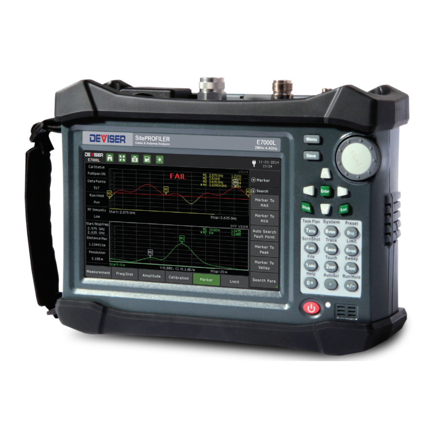
E7000L
SitePROFILER
Handheld Cable & Antenna Analyzer
User Guide
Version 160823
™
Table of
Contents
Previous
Page
Next
Page
1
2
3
4
5
Advertisement
Table of Contents
Need help?
Do you have a question about the SitePROFILER and is the answer not in the manual?
Ask a question
Questions and answers
Subscribe to Our Youtube Channel
Related Manuals for Deviser SitePROFILER
Measuring Instruments Deviser S7000 Series Operation Manual
Tv analyzer (188 pages)
Measuring Instruments Deviser S7000 Operation Manual
Tv analyzer (136 pages)
Measuring Instruments Deviser S30 Operation Manual
Satellite meter (30 pages)
Measuring Instruments Deviser S7200 User Manual
Tv signal spectrum analyzer (149 pages)
Measuring Instruments Deviser TC500 Operation Manual
Ethernet cabling certifier (42 pages)
Measuring Instruments Deviser FC-1 Operation Manual
High-performance portable platform (28 pages)
Measuring Instruments Deviser DS2400T Operation Manual
Dvb-t2 signal analysis meter (112 pages)
Measuring Instruments Deviser C1200 Operation Manual
Dvb-c meter (27 pages)
Measuring Instruments Deviser DS2831 User Manual
Digital tv spectrum analyzer (178 pages)
Measuring Instruments Deviser DS2002 Operation Manual
Signal level meter (22 pages)
Measuring Instruments Deviser DS2400B Operation Manual
Signal level meter (105 pages)
Measuring Instruments Deviser DS100 Instruction Manual
Interference and direction analyzer (32 pages)
Measuring Instruments Deviser DS2400Q Operation Manual
(121 pages)
Measuring Instruments Deviser E8900A User Manual
5g nr spectrum analyzer (150 pages)
Measuring Instruments Deviser DS2460Q Operation Manual
Qam analysis meter (167 pages)
Measuring Instruments Deviser AE120 User Manual
Optical power meter (13 pages)
This manual is also suitable for:
E7000l
Table of Contents
Print
Rename the bookmark
Delete bookmark?
Delete from my manuals?
Login
Sign In
OR
Sign in with Facebook
Sign in with Google
Upload manual
Upload from disk
Upload from URL


Need help?
Do you have a question about the SitePROFILER and is the answer not in the manual?
Questions and answers