
Related Manuals for Deviser DS2400B


Summary of Contents for Deviser DS2400B
- Page 1 : :...
- Page 3 © Tianjin Deviser Electronics Instrument Co., Ltd. Deviser Part No.: 2400-DL All rights reserved. Printed in CHINA. April. 2011.
- Page 5 LCD). Users should read manual carefully before first use and operate correctly according to the manual. Deviser shall have no responsibility for any defect or damage caused by improper use and maintenance or for any product which has been repaired or altered by any one other not DEVISER or our authorized service center.
-
Page 7: Table Of Contents
1.9 Multiple User Channel ······································ 5 1.10 File Management ··········································· 5 1.11 Intelligent Power Management ······················ 5 2. Introduction............7 2.1 Appearance ······················································ 7 2.2 Keypad ······························································ 8 2.2.1 Soft keys ···················································· 8 2.2.2 Shortcut keys············································· 8 2.2.3 Character/Digit Input ································ 8 DS2400B... - Page 8 3.6 Spectrum Scanning ········································· 36 3.6.1 Soft Keys Operation ································ 36 3.6.2 Parameter Setting ··································· 38 3.7 HUM Measurement ········································ 42 3.7.1 Soft Keys Operation ································ 43 3.8 Limit Measurement ········································ 44 3.8.1 Test Results List ······································· 45 3.8.2 Limit Edit ·················································· 47 DS2400B...
- Page 9 4.2 INFORMATION ················································ 69 4.3 GENERAL ··························································70 4.3.1 Shutdown Time ········································70 4.3.2 Language Selection ································· 71 4.3.3 Date and Time ········································ 71 4.3.4 Files Status ···············································72 4.3.5 System upgrade······································· 73 4.4 Measurement Parameter Setup ····················· 73 4.4.1 Level Unit ················································ 73 DS2400B...
- Page 10 4.5.2 Channel Number Type ···························· 83 4.5.3 Learn User Plan ······································· 83 4.5.4 Edit User Plan ·········································· 84 5. Power Supply ............87 5.1 Battery ·····························································87 6. Port ..............89 7. Specification ............90 8. Standard Accessories .......... 94 DS2400B...
-
Page 11: General Introduction
DS2400B Signal Level Meter Operation Manual 1. General Introduction DS2400B is new model with color screen and high performance, which is developed for Analog TV analysis by Deviser. This model can measure and display most indexes of Digital TV (Channel Power);... - Page 12 DS2400B Signal Level Meter Operation Manual Features: * Level Test * Channel Scanning * Spectrum * Tilt * HUM * Voltage Measurement * Multiple User Channel Plan Setup * File Management * Intelligent Power Management * Character /Numeral Input * Shortcut Setup...
-
Page 13: Channel Measurement
DS2400B support 12 channels tilt max. 1.3 Channel Scanning DS2400B supports video and audio level display of all channels, which could up to 160 channels most. Also its zoom in/out of 5 levels and marker function make your observation easier. -
Page 14: Hum Measurement
1.6 Limit Measurement DS2400B can fast check the cable system by the limit test function. Each enabled channel will be tested according to the limits set by user, and after the testing, pass/fail indicator can be viewed. -
Page 15: Voltage Measurement
TV channel. User can manage and analyze these files via meter or PC. 1.11 Intelligent Power Management DS2400B with full charged is able to work over 5 hours. The power supply monitoring system will monitor the status of power and ensure the instrument in power... - Page 16 DS2400B Signal Level Meter Operation Manual saving mode. NOTE: Charge the battery before first use. Refer to 5 DS2400B...
-
Page 17: Introduction
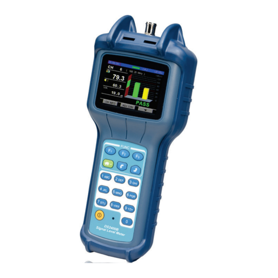
DS2400B Signal Level Meter Operation Manual 2. Introduction 2.1 Appearance Get acquainted with the appearance before use: RF Interface Keyboard POWER Charge Status Serial Charge Port Interface DS2400B... -
Page 18: Keypad
DS2400B Signal Level Meter Operation Manual 2.2 Keypad 2.2.1 Soft keys There are three soft keys ( located under the screen. They are used to access the functions represented by the icons displayed on the bottom of screen. 2.2.2 Shortcut keys... -
Page 19: Using The Instrument
DS2400B Signal Level Meter Operation Manual 3. Using the Instrument 3.1 Function Menu Display Figure3-1-1 The Figure3-1-1 Display the Main Menu which include all of the function icons, Soft Keys: : Enter the selected shortcut interface. : Switch the selected shortcut on the left direction circularly. -
Page 20: Learn User Channel Plan
3.2 Learn User Channel Plan In order to enhance your work efficiency, please create user channel plan before measurement. DS2400B will choose all effective channels in the cable system automatically and save in this channel plan. The User Channel Plan includes three elements as... - Page 21 DS2400B Signal Level Meter Operation Manual The following is the step of setup user channel plan. 1. Connect the instrument with the cable system. 2. Press return to main menu, and select the Setup shortcut like Figure3-2-1, then press into Setup Menu.
- Page 22 DS2400B Signal Level Meter Operation Manual Figure3-2-2 Now press into Figure3-2-3 CHANNEL PLAN, then press select the user channel plan. Figure3-2-3 DS2400B...
- Page 23 DS2400B Signal Level Meter Operation Manual Press to select the LEARN CHANNEL PLAN item, and press , the LEARN CHANNEL PLAN function displays as Figure 3-2-4. Figure3-2-4 Press to select one channel type. Press into Parameter setting, you can define the channel plan as Analogue channel plan, digital channel plan or analog/digital mixed channel plan.
- Page 24 DS2400B Signal Level Meter Operation Manual press to START, then press to creat your user channel plan. For a while, new user plan will be saved automatically. NOTE: The analog channels with level higher than 45dBμV and digital channel with power level higher than 32dBμV will be enabled in standard channel...
-
Page 25: Level Measurement
DS2400B Signal Level Meter Operation Manual 3.3 Level Measurement Press return to main menu, press the to select the Level shortcut as Figure3-3-1.Then press Figure3-3-1 If there is no valid channel to test, the screen will display as figure 3-3-2. Now, if you want to do any test... - Page 26 DS2400B Signal Level Meter Operation Manual Figure3-3-2 The channel list will display as figure 3-3-3. Press to select the channel, and here, Press will page up or page down the channel list. Then press into channel information as figure 3-3-4.
-
Page 27: Analogue Channel Measurement
DS2400B Signal Level Meter Operation Manual Figure 3-3-4 Press select channel parameters, if the selected parameter could be changed, press to change. As the figure 3-3-4, ensuring the STATUS is enable, the channel will be enabled. 3.3.1 Analogue channel measurement... - Page 28 DS2400B Signal Level Meter Operation Manual : Video Level : Audio Level Figure3-3-5 CH INFO ( ): Press this button will display the channel information of this analogue channel as figure 3-3-6. The channel parameters also can be modified in this screen.
- Page 29 DS2400B Signal Level Meter Operation Manual Figure 3-3-6 ONE CHN/ADJ CHN ( ): The user can switch from both of two display mode (One channel and three channels): One channel mode: The histogram show the video and audio of current channel only.
- Page 30 DS2400B Signal Level Meter Operation Manual Figure 3-3-7 ): Press this button to next page as figure 3-3-8, the user can press this button again to return. Figure 3-3-8 DS2400B...
- Page 31 DS2400B Signal Level Meter Operation Manual is used for switch channels circularly. If the next channel is digital channel, the screen will be changed. (Refer to next section.) SAVE( ): Press this button to save the result of level test ,refer to 3.10.2.
-
Page 32: Digital Channel Measurement
DS2400B Signal Level Meter Operation Manual 3.3.2 Digital channel measurement In this function DS2400B is able to measure POWER. As figure 3-3-10. Figure3-3-10 CH INFO ( ): Press this button will display the channel information of this digital channel, as figure 3-3-11. - Page 33 DS2400B Signal Level Meter Operation Manual Figure 3-3-11 ONE CHN/ADJ CHN ( ): The user can switch from both of two display mode (One channel and Three channels): One channel mode: The histogram shows the video and audio of current channel only.
- Page 34 DS2400B Signal Level Meter Operation Manual Figure 3-3-12 ): Press this button to next page as figure 3-3-13, the user can press this button again to return. Figure 3-3-13 are used for switching channels circularly. If the next channel is analogue channel, the screen will be displayed as figure 3-3-5.
- Page 35 DS2400B Signal Level Meter Operation Manual SAVE( ): Press this button to save the result of level test ,refer to 3.10.2. FREQ( ): Press this button into frequency measurement interface as figure 3-3-14, In this mode, the user can easily modify the central frequency, but...
-
Page 36: Limit Display
DS2400B Signal Level Meter Operation Manual Figure 3-3-14 RENEW: Press this button can test again. 3.3.3 Limit Display A PASS or FAIL in big font is displayed in the screen to indicate the quality of current channel as the figure... -
Page 37: Tilt/Level List Measurement
DS2400B Signal Level Meter Operation Manual 3.4 Tilt/Level List Measurement Tilt/Level list test is the effective solution to check the flatness and splitter’s gain of cable system, DS2400B can get levels of 12 channels and observe the measurement result and graph easily. - Page 38 DS2400B Signal Level Meter Operation Manual In Figure 3-4-1, press to enter the tilt channels setup menu, select the channels that you want to do tilt test as Figure 3-4-2; press change the highlight line, and then press the to select or unselect the channel,...
-
Page 39: Tilt Mode
DS2400B Signal Level Meter Operation Manual After selected,Press to enter the Tilt/Level List measurement. Now the Tilt measurement can be continued. 3.4.1 Tilt Mode In tilt test interface, the channels will be displayed as histogram, and test result will be displayed at the bottom of screen as Figure 3-4-3. -
Page 40: Level List Mode
DS2400B Signal Level Meter Operation Manual Figure 3-4-4 SAVE ( ):Press SAVE soft key and enter into Figure 3-10-2 to save the result of tilt test ,refer to 3.10.2. SETUP ( ): When testing, press SETUP soft key and enter into Figure 3-4-2 to re-select tested channels. - Page 41 DS2400B Signal Level Meter Operation Manual 3.4.2.1 Soft Keys Operation LIST ( ): Press GRAPH soft key to enter Tilt mode, as Figure 3-4-3. SAVE ( ):Press SAVE soft key and enter into Figure 3-10-2 to save the result of tilt test ,refer to 3.10.2.
-
Page 42: Channel Scanning
DS2400B Signal Level Meter Operation Manual 3.5 Channel Scanning DS2400B support channel scanning function in order to test the flatness and amplitude of cable TV system quickly. Press to return to main menu interface and press to select the SCAN icon, and... -
Page 43: Soft Keys Operation
DS2400B Signal Level Meter Operation Manual Green color represents video level of analogue channels. Yellow color represents audio level of analogue channels. Blue color represents power of digital channels. The scan function also display the channel number of scanning start channel and end channel. - Page 44 DS2400B Signal Level Meter Operation Manual REFERENCE LEVEL: Press TAB to select the REF, and then it can be modified by press , the range of reference level: 0-120 dBuV . VIEW: Press TAB to select the VIEW and switch between ×1, ×2, ×3, ×4 and ×5 by pressing...
- Page 45 DS2400B Signal Level Meter Operation Manual adjust them to most optimal state. ):Press this button to next page as figure 3-5-2, the user can press this button again to return. Figure 3-5-2 soft key SAVE ( ):Press SAVE and enter into Figure 3-10-2 to save the result of tilt test ,refer to 3.10.2.
-
Page 46: Spectrum Scanning
DS2400B Signal Level Meter Operation Manual 3.6 Spectrum Scanning Press to return to main menu interface and press to select the spectrum icon, and then press to enter spectrum function. DS2400B’s spectrum function supports double-marker display and peak-hold function as Figure 3-6-1. Here, you can set up span, frequency, sampling mode and etc…. - Page 47 DS2400B Signal Level Meter Operation Manual ,or by figure Input directly. AUTO ( ): Press AUTO soft key to adjust reference level and scale quickly . The meter will automatically adjust them to most optimal state. ):Press this button to next page as figure 3-6-2, the user can press this button again to return.
-
Page 48: Parameter Setting
DS2400B Signal Level Meter Operation Manual 3.6.2 Parameter Setting You can modify or adjust measurement parameter. Press can highlight the selected parameter and then press press character/digit keys directly. Figure3-6-3 REFERENCE LEVEL: After selecting the REF parameter, show as figure 3-6-2, press to adjust the reference level. - Page 49 DS2400B Signal Level Meter Operation Manual AVG: sample average mode, the display result of each point will be an average of several sample value. It will be faster than the PEAK mode, and also if you want to measure the noise of the system, you need to select this mode.
- Page 50 DS2400B Signal Level Meter Operation Manual to choose one scale from 1dB/, 2dB/, 5dB/ and 10dB/. CENTER FREQUENCY: After selecting the CENT parameter, you can input the center frequency by the character/digit keys. Note: Any frequency from 5 to 1000MHz can be input.
- Page 51 DS2400B Signal Level Meter Operation Manual point. MARKB: After selecting the MARKB parameter, the purple marker B becomes active marker, pressing can move the purple marker to the wanted view point. DS2400B...
-
Page 52: Hum Measurement
DS2400B Signal Level Meter Operation Manual 3.7 HUM Measurement DS2400B support HUM measurement to analogue channel. Press to return to main menu interface and press to select the HUM icon, and then press to enter HUM function. Show as Figure 3-7-1. -
Page 53: Soft Keys Operation
DS2400B Signal Level Meter Operation Manual 3.7.1 Soft Keys Operation 50Hz/60Hz( ):After pressing 50Hz or 60Hz soft key, the DS2400B will select the frequency of system power as figure 3-7-2. Figure 3-7-2 are used to switch analogue channels circularly. Also you can input the channel number using the character/digit keys. -
Page 54: Limit Measurement
LIMIT icon, and then press to enter LIMIT function. As shown in figure 3-8-1, DS2400B is able to detect cable TV system rapidly, and check out the number of unqualified channels and the reason of unqualified channels. The amplitude of each channel of selected user plan is checked one by one. -
Page 55: Test Results List
DS2400B Signal Level Meter Operation Manual NOTE: DS2400B checks the analog channel only in Limit Test mode. 3.8.1 Test Results List After the limit test scanning, the general test results of cable system will be listed. The test items are consist of minimum video level, maximum video level, maximum delta video level, minimum △V/A,... - Page 56 DS2400B Signal Level Meter Operation Manual Press to list as figure 3-8-3. Figure 3-8-3 Press to view the graph as figure 3-8-4. Figure 3-8-4 DS2400B...
-
Page 57: Limit Edit
DS2400B Signal Level Meter Operation Manual ):Press this button to next page as figure 3-8-5, the user can press this button again to return. Figure 3-8-5 RETEST ( ):Press RETEST to retest. soft key SAVE ( ):Press SAVE and enter into Figure 3-10-2 to save the result of tilt test ,refer to 3.10.2. -
Page 58: Auto Test
DS2400B Signal Level Meter Operation Manual Figure 3-8-6 If you want to change a parameter ,press select the parameter, press to change. Press to LOAD DEFAULT ,and then press you can select the default. 3.9 Auto Test Press key to the main menu, press to select the AUTO icon and then press enter. -
Page 59: Create New Project
Figure 3-9-1 3.9.1 Create New Project Highlight blank space by , and then press button, DS2400B will guide you to build a new project step by step. Step 1:Create Project Name Press to create a new project as Figure 3-9-2. - Page 60 DS2400B Signal Level Meter Operation Manual Figure 3-9-2 Step 2:Select test items The auto test includes five items (Level test, Spectrum, Limit test , Tilt and HUM ). Select the test items by keys, and disable or enable it by pressing .
- Page 61 DS2400B Signal Level Meter Operation Manual Figure 3-9-3 Step 3:Edit test items According to different test items, it will appear corresponsive parameter setting, as figure 3-9-4. Figure 3-9-4 When edit LEVEL test parameter, move the cursor by and disable or enable...
- Page 62 DS2400B Signal Level Meter Operation Manual the measured channels by pressing .The channel marked by "√" will be tested in LEVEL item of auto test procedure. Be sure to confirm the entry by pressing button and return to previous menu, as figure 3-9-5.
- Page 63 DS2400B Signal Level Meter Operation Manual Figure 3-9-6 When you edit SPECT parameter, you are able to edit center frequency/span as figure 3-9-7. Figure 3-9-7 DS2400B...
- Page 64 DS2400B Signal Level Meter Operation Manual When edit HUM test parameter, move the cursor and disable or enable the measured channels by pressing . The analog channel marked by "√" will be tested in HUM item of auto test procedure. Be sure to...
- Page 65 DS2400B Signal Level Meter Operation Manual Figure 3-9-9 Step 4:Auto Start After editing limit test parameter, press button and return to previous menu, Press to start the auto test. DS2400B...
-
Page 66: Auto Test Storage
DS2400B Signal Level Meter Operation Manual 3.9.2 Auto Test Storage After the auto test ,the file name will be auto marked with a “*” as in figure 3-9-10,user can change the name by himself. Figure 3-9-10 DS2400B... -
Page 67: File Management
FILE icon, and then press to enter FILE management function as Figure 3-10-1. DS2400B has independent memory space to store the measurement data. The measurement data of level test (analogue channels), channel scan, tilt, frequency spectrum measurement and HUM can be stored into files. -
Page 68: Save File
“ NEW ”, press this button, a “SAVE THE FILE” dialog show as figure 3-10-3, DS2400B will give a default name for new file, also you can rename it using the character/digit keys. After rename the new file, press... - Page 69 DS2400B Signal Level Meter Operation Manual been listed, and the default status is that all parameters have been selected as figure 3-10-4. Figure 3-10-2 Figure 3-10-3 DS2400B...
- Page 70 DS2400B Signal Level Meter Operation Manual Figure 3-10-4 Press to modify the cursor location, and then press to select or unselect the data item as figure 3-10-5, press to save the file. When the new file was saved, the file list menu display as figure 3-10-6.
-
Page 71: Read File
DS2400B Signal Level Meter Operation Manual Figure 3-10-6 3.10.3 Read File Press to select the file you would like to read, and then press to Load the file. ”LOAD THE FILE ” dialog will display as figure 3-10-7. Figure 3-10-7... - Page 72 DS2400B Signal Level Meter Operation Manual Normally, the data items can be opened using LIST mode( ), press to select the data item, and then press (LIST) to list a data item in LIST mode as figure 3-10-8, 3-10-9, 3-10-10, 3-10-11, 3-10-12, 3-10-13, 3-10-14.
- Page 73 DS2400B Signal Level Meter Operation Manual Figure 3-10-10 Figure 3-10-11 DS2400B...
- Page 74 DS2400B Signal Level Meter Operation Manual Figure 3-10-12 Figure 3-10-13 DS2400B...
-
Page 75: Delete File
DS2400B Signal Level Meter Operation Manual Figure 3-10-14 3.10.4 Delete File Select one file by press and press DELETE( ) to delete this selected file, the “DELETE FILE” dialog will display as figure 3-10-15. Figure 3-10-15 DS2400B... - Page 76 DS2400B Signal Level Meter Operation Manual Press (ENTER) in figure 3-10-15, the file will be deleted as figure 3-10-16. Figure 3-10-16 DS2400B...
-
Page 77: Setup
DS2400B Signal Level Meter Operation Manual 4. Setup 4.1 Brief Introduction Press to return to main interface and press to select the SETUP icon, and then press to enter SETUP menu as Figure 4-1-1. Figure 4-1-1 *INFORMATION: General information of the DS2400B,... - Page 78 DS2400B Signal Level Meter Operation Manual files status and system upgrade(NOT INSTALL) . * MEASUREMENT: Level unit, Level Calibrate, Limit setup and Voltage & temperature measurement. * CHANNEL PLAN : The setup for channel plan includes user plan selection, learn and edit user plan.
-
Page 79: Information
DS2400B Signal Level Meter Operation Manual 4.2 INFORMATION This is the information of the instrument, Refer to Figure 4-2-1. It includes serial number, software version , hardware version and so on. Figure 4-2-1 DS2400B... -
Page 80: General
DS2400B Signal Level Meter Operation Manual 4.3 GENERAL 4.3.1 Shutdown Time To save the power, the instrument can be set to shutdown automatically for inactive keypad after 3 minutes, 5 minutes, 10 minutes ,30 minutes and ON(never shutdown mode ), as Figure 4-3-1. -
Page 81: Language Selection
DS2400B Signal Level Meter Operation Manual 4.3.2 Language Selection The language of DS2400B can switch among English, and Chinese as figure 4-3-2. After choose, instrument will transform menu automatically. Figure 4-3-2 Note Contact Deviser for more languages. : 4.3.3 Date and Time... -
Page 82: Files Status
DS2400B Signal Level Meter Operation Manual Figure 4-3-3 4.3.4 Files Status This interface shows the number of files have been saved, and also show the Memory status as figure 4-3-4. Figure 4-3-4 DS2400B... -
Page 83: System Upgrade
DS2400B Signal Level Meter Operation Manual 4.3.5 System upgrade This function is not installed. 4.4 Measurement Parameter Setup 4.4.1 Level Unit Figure 4-4-1 4.4.2 Level Calibrate Figure 4-4-2 DS2400B... -
Page 84: Limit Setup
DS2400B Signal Level Meter Operation Manual User can make amendment and compensation of the measure data in all level measurement function, press MODIFY( ) to highlight the level offset box and then press to adjust it and press ENTER( ) to enable the input data. - Page 85 DS2400B Signal Level Meter Operation Manual Figure 4-4-4 Figure 4-4-5 Three pages of Limit setting have been provided as Figure 4-4-3, Figure 4-4-4, Figure 4-4-5, Four Limit items included in page one(1/3) , which is used for single analogue channel test, The default value of these Limit items are list as Table 4-4-1.
- Page 86 DS2400B Signal Level Meter Operation Manual between MAX VIDEO and MIN VIDEO must be larger than six dB. Item Limit Minimum Video level 60dBμV Minimum △ V/A Maximum Video level 100dBμV Maximum △ V/A 10dB 20dB Table 4-4-1 Item Limit Minimum Video level 30~99dBμV...
- Page 87 DS2400B Signal Level Meter Operation Manual Item Limit Minimum Power level 50dBμV Maximum Power level 90dBμV Table 4-4-3 Item Limit Minimum Power level 25~89dBμV Maximum Power level 26~110dBμV Table 4-4-4 Page three(3/3) is used for tilt measurement, one limit items list including of MIN TILT and MAX TILT. The default value of these Limit items are list as Table 4-4-5.
-
Page 88: Auto Diagnosis
DS2400B Signal Level Meter Operation Manual To set the test limit, you can choose limit item by press TAB( ), and then press to adjust it. If you want to load default values of all limit items on each page, please press the TAB(... -
Page 89: Voltage And Temperature
DS2400B Signal Level Meter Operation Manual Figure 4-4-6 NOTE: Before the auto diagnosis function can be work correctly, the Limit items in section 4.4.3 must be set the valid values. 4.4.5 Voltage and temperature The button “VOL & TEMP” here is used to enter the measurement interface Figure 4-4-7. -
Page 90: Trunk Voltage(Ac Line)
DS2400B Signal Level Meter Operation Manual Figure 4-4-7 4.4.5.2 Trunk Voltage(AC LINE) This meter will automatically judge whether it is AC or DC in the trunk, and display the trunk voltage on the screen as Figure 4-4-8. Figure 4-4-8 DS2400B... -
Page 91: Temperature Inside
DS2400B Signal Level Meter Operation Manual 4.4.5.3 Temperature Inside DS2400B can monitor inside temperature itself, and you can press to choose the display unit: Celsius or Fahrenheit, refer to Figure 4-4-9 and Figure 4-4-10. Figure4-4-9 Figure4-4-10 DS2400B... -
Page 92: Channel Plan
A, B, C, D, and E. User can choose one as current user plan as Figure 4-5-1. Then, the meter will measure according to the selected the user plan. Figure 4-5-1 NOTE: DS2400B has five default user plans. DS2400B... -
Page 93: Channel Number Type
DS2400B Signal Level Meter Operation Manual 4.5.2 Channel Number Type You can set the channel number to be displayed in digital(numeric) mode or standard (alphanumeric) mode. After choose, the meter will show the channel number as you desired in any measurement mode. -
Page 94: Edit User Plan
DS2400B Signal Level Meter Operation Manual NOTE: The LEARN USER PLAN option will build the new user plan and replace the current selected user plan. If build other user plans, you can enter into SELECT USER PLAN and then make the LEARN USER PLAN operation. - Page 95 DS2400B Signal Level Meter Operation Manual Figure 4-5-3 EDIT CHANNEL PLAN will show the channels list on the screen as Figure4-5-3 , you can only exit this function by press the HOME( ) key, press to highlight one channel, and press edit status as Figure 4-5-4.
- Page 96 DS2400B Signal Level Meter Operation Manual Figure 4-5-4 NOTE Any edit here will be saved when you exit the : screen. DS2400B...
-
Page 97: Power Supply
DS2400B Signal Level Meter Operation Manual 5. Power Supply 5.1 Battery DS2400B uses built-in 12.6V 1.5AH Li-Polymer battery and works over 5 when fully charged. When the voltage of the battery drops below 11V, the battery icon flashes in screen. Once the voltage of the battery is lower than 10.6V, the instrument will shut down... - Page 98 DS2400B Signal Level Meter Operation Manual 5.2 Charging Please charge the instrument as following charging process: 1. Insert the charger output plug to DS2400B’ DC charge socket. 2. Connect the charger to AC 100V-240V Power and the charger indicator will light with red.
-
Page 99: Port
DS2400B Signal Level Meter Operation Manual 6. Port The instrument can communicate with a PC through the 5 Pin communication port. Refer to figure 6-1. Figure 6-1 1 ---- TXD 2 ---- RXD 3 ---- NC 4 ----+5V 5 ---- GND Management PC software- Toolbox is provided as standard. -
Page 100: Specification
DS2400B Signal Level Meter Operation Manual 7. Specification Frequency: Range: 5MHz to 1000MHz Accuracy: ±50×10 (20℃±5℃) Resolution: 10 KHz Receive 280 KHz Channel Type: Analogue TV: Digital TV: POWER Analog Level Measurement: Range: 30dBµV to 120dBµV Accuracy: ±1.5dB Resolution: 0.1dB Input 75Ω... - Page 101 DS2400B Signal Level Meter Operation Manual 1MS/S-7MS/S Enactment bandwidth: Power measure QAM QPSK COFDM type: Average Power Level range: 30dBµV to 110dBµV Accuracy: ±2.0dB resolution: 0.1dB Channel Scan: Number of 160 channels max. channels: Scanning speed: 5 channels/ s Scale:...
- Page 102 DS2400B Signal Level Meter Operation Manual Tilt measurement: Number of 4 to 12 channels: Resolution: 0.1dB Trunk Voltage measurement: Input range: 0V to 100V (AC/DC) Accuracy: ±2V Resolution: 0.1V Other function: Storage: 512K byte Communication RS 232C Port: Store -20℃~50℃...
- Page 103 DS2400B Signal Level Meter Operation Manual Charger: AC 100 V to 240V 50-60Hz Work time: 5 hours (full charged battery) Charge time: ~ 3hours DS2400B...
-
Page 104: Standard Accessories
DS2400B Signal Level Meter Operation Manual 8. Standard Accessories Standard Accessories Quantity DS2400B AC-DC power adapter/charger Carrying bag F and BNC connect Manual CD Option Accessories Quantity Data cable(Serial to USB) and Toolbox software CD DS2400B... - Page 105 E‐mail: sales@deviserinstruments.com E‐mail: overseasbiz@deviser.com.cn 95 DS2400B ...
Need help?
Do you have a question about the DS2400B and is the answer not in the manual?
Questions and answers