
Related Manuals for Thermo Scientific Dionex ICS Series


Summary of Contents for Thermo Scientific Dionex ICS Series
- Page 1 Dionex ICS Series VWD Variable Wavelength Detector Operator’s Manual Document No. 065377 Revision 01 January 2012...
- Page 2 © 2012 Thermo Fisher Scientific Inc. All rights reserved. Atlas, BioLC, Chromeleon, and SRS Self-Regenerating Suppressor are registered trademarks of Thermo Fisher Scientific Inc. in the United States. Acrobat, Adobe, and Adobe Reader are registered trademarks of Adobe Systems Incorporated in the United States and other countries. KIMWIPES is a registered trademark of Kimberly-Clark Corporation in the United States and possibly other countries.
-
Page 3: Table Of Contents
Contents 1 • Introduction Detector Overview ......... . 1 Principles of Operation . - Page 4 Dionex VWD Operator’s Manual 2.4.4 Analog Outputs (Optional) ......17 2.4.5 Tubing Chase ........18 2.4.6 Drain Port and Drain Tube .
- Page 5 Contents 3.5.4 Average (Chromeleon 6.8 only) ......37 3.5.5 Sample Wavelength Selection ......37 Shutdown .
- Page 6 Dionex VWD Operator’s Manual Replacing a Tungsten Lamp ........69 Cleaning the Flow Cell .
- Page 7 Contents Connecting the Drain Tube ........88 Connecting the Digital I/O .
- Page 8 Dionex VWD Operator’s Manual Doc. 065377-01 1/12...
-
Page 9: Introduction
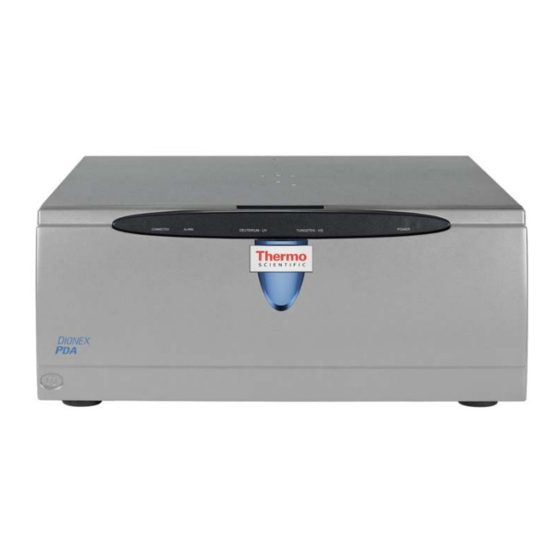
1 • Introduction Detector Overview Figure 1-1. Thermo Scientific Dionex ICS Series Variable Wavelength Detector ™ The Thermo Scientific Dionex ICS Series Variable Wavelength Detector (Dionex VWD) is a high-quality instrument designed for IC analysis applications requiring a UV-Vis detector and for LC analysis applications requiring an inert ™... - Page 10 The detector is controlled with a PC (personal PC) running Microsoft ® ® Windows Vista or Windows XP and either the Thermo Scientific Dionex ® ® Chromeleon 7 Chromatography Data System or Chromeleon Chromatography Data System. Chromeleon 7 and Chromeleon 6.8 also provide data acquisition and data processing functions.
-
Page 11: Principles Of Operation
1 • Introduction Principles of Operation Photometric detection is based upon the absorption of monochromatic light. The degree of absorption depends on the sample molecule, its concentration, the light's path length in the sample, and the measurement wavelength. Absorbance is defined as: ... -
Page 12: About This Manual
Dionex VWD Operator’s Manual About This Manual The electronic version (i.e., PDF file) of the Dionex VWD operator’s manual contains numerous hypertext links that can take you to other locations within the file. These links include: • Table of contents entries •... -
Page 13: Safety And Regulatory Information
1 • Introduction Appendix C Spare parts for the Dionex VWD. Reordering Information Appendix D UV cutoff wavelengths of common mobile phases and UV Absorbances wavelengths for the absorption maxima of various chromophores. Safety and Regulatory Information The Dionex VWD was manufactured by Thermo Fisher Scientific Corporation at the following location: 527 Lakeside Drive, Sunnyvale, CA 94088-3603 U.S.A. - Page 14 Dionex VWD Operator’s Manual Indicates that the function or process of the instrument may be impaired. Operation does not constitute a hazard. Messages d'avertissement en français Signale une situation de danger immédiat qui, si elle n'est pas évitée, entraînera des blessures graves à mortelles. Signale une situation de danger potentiel qui, si elle n'est pas évitée, pourrait entraîner des blessures graves à...
-
Page 15: Safety Symbols
1 • Introduction 1.4.2 Safety Symbols These symbols appear on the Dionex VWD or on labels affixed to the Dionex VWD: Alternating current Primary protective conductor terminal Secondary protective conductor terminal Power supply is on Power supply is off Indicates a potential hazard. Refer to this operator’s manual for an explanation of the hazard and how to proceed. - Page 16 Dionex VWD Operator’s Manual Doc. 065377-01 1/12...
-
Page 17: Description
ICS Series Variable Wavelength Detector (Dionex VWD). Status Bar Power Button Front Cover Figure 2-1. Thermo Scientific Dionex ICS Series Variable Wavelength Detector Front Features • Use the power button in the lower left corner of the detector for routine on/off control of the Dionex VWD. - Page 18 Dionex VWD Operator’s Manual • The front cover provides access to the interior components of the Dionex VWD. To remove the cover, grasp the cover by the sides and pull it straight off. • The status bar provides LEDs (light emitting diodes) that indicate the status of several detector functions (see Figure 2-2).
-
Page 19: Interior Components
2 • Description Interior Components To access the interior components of the Dionex VWD, grasp the front cover by the sides and pull it straight off. Tubing Slots Flow Cell Tubing Chase Lamp Housing Cover Leak Sensor Leak Drain Figure 2-3. Dionex VWD Interior View (Front Cover Removed) 2.2.1 Tubing Slots and Tubing Chase The tubing slots route tubing (for example, the flow cell inlet tubing) -
Page 20: Flow Cells
Dionex VWD Operator’s Manual fixing the leak and drying the sensor, clear the LED (see ALARM Section 4.2). 2.2.3 Flow Cells A flow cell is not included with the Dionex VWD and must be specifically ordered. Dionex offers two PEEK cells for use with the Dionex VWD: •... -
Page 21: Lamps
2 • Description 2.2.4 Lamps The detector is shipped with a deuterium lamp (P/N 066347) for UV wavelength detection and a tungsten lamp (P/N 066348) for visible and near-infrared wavelength detection. The wavelength detection range is from 190 to 900 nm. The table below lists the lamp(s) to use for various wavelength detection ranges. - Page 22 Dionex VWD Operator’s Manual the flow cell (12) to the detector (13), where the absorbance of the analyte is measured and processed. Figure 2-4. Dionex VWD Optical System Component Description Tungsten lamp Light source for the visible and near-infrared wavelengths (345 to 900 nm).
- Page 23 2 • Description Component Description Entrance slit Limits the bandwidth of the light that is directed to the flow cell. Mirror Directs the light to the optical grating. Optical grating Grating (1800 l/mm) selects the wavelength of light impinging on the sample. Mirror Directs the diffracted, monochromatic light from the grating to the flow cell.
-
Page 24: Rear Panel
Dionex VWD Operator’s Manual Rear Panel Figure 2-5 illustrates the rear panel of the Dionex VWD. Main Power Switch, Fuse Analog Outputs (optional) Cartridge, Power Receptacle Tubing Chase Digital I/O Ports Drain Port USB Receptacle Figure 2-5. Dionex VWD Rear Panel (Analog Output Connectors not Installed) 2.4.1 Main Power Switch, Fuse Cartridge, and Power... -
Page 25: Digital I/O Ports
2 • Description The fuse cartridge contains two IEC 60127-2 time lag fuses (P/N 954776) rated at 2 A, 250 VAC. For instructions on how to change the fuses, see Section 5.7. The power cord plugs into the IEC 320 three-prong receptacle. The power supply cord is used as the main disconnect device. -
Page 26: Tubing Chase
Dionex VWD Operator’s Manual such as an integrator or other recording device. Refer to Section B.7 the documentation for the device for connection instructions. You can select the output mode, offset, and range in the Chromeleon 7 Command window or the Chromeleon 6.8 Commands dialog box. Table 2-1 describes the available settings Analog Output... -
Page 27: Drain Port And Drain Tube
2 • Description 2.4.6 Drain Port and Drain Tube Liquid (for example, from a leak) is routed from the drip tray inside the detector to the drain port on the rear panel. Connect the drain tube (P/N 055075), provided in the Dionex VWD Ship Kit (P/N 064787), to the port. -
Page 28: Mobile Phase Delivery System
Dionex VWD Operator’s Manual • Strong bases can etch the silica windows of the flow cell. If the mobile phase is a base, make sure the mobile phase concentration does not exceed 0.1 M. If the concentration of the base is greater than 50 mM, disconnect the separator column and flush the system with ASTM Type I (18 megohm-cm) filtered, deionized water for 5 minutes at 1.0 mL/min immediately after the analysis. -
Page 29: Chromatography Software
2 • Description Chromatography Software 2.6.1 Overview The Dionex VWD is controlled by a PC configured with either the Chromeleon 7 Chromatography Data System or the Chromeleon 6.8 Chromatography Data System. Both software products provide extensive instrument control, data management, reporting, and compliance features. In Chromeleon 7, an ePanel Set provides centralized system control. - Page 30 Dionex VWD Operator’s Manual Figure 2-7 shows the Dionex VWD Control panel in Chromeleon 6.8. Figure 2-7. Example Dionex VWD Control Panel in Chromeleon 6.8 Two modes of software control are available: direct control and automated control. • With direct control, you select operating parameters and commands from the Chromeleon 7 Command window and ePanel or the Chromeleon 6.8 Commands dialog box and Control panel.
-
Page 31: System Wellness And Predictive Performance
2 • Description program in Chromeleon 6.8). The commands are executed at specific times, allowed automated operation of the detector. Instrument methods and programs can be created automatically (with the help of a software wizard) or manually (by editing an existing instrument method or program). - Page 32 Dionex VWD Operator’s Manual Doc. 065377-01 1/12...
-
Page 33: Operation And Maintenance
3 • Operation and Maintenance Startup 3.1.1 Initial Startup To start the Thermo Scientific Dionex ICS Series Variable Wavelength Detector (Dionex VWD) for the first time, turn on the main power switch on the rear panel of the detector (see Figure 2-5). -
Page 34: Connect To The Chromeleon 7 Client
Dionex VWD Operator’s Manual 3.1.2 Connect to the Chromeleon 7 Client 1. Start the Instrument Controller Service, if it is not already running. If the Chromeleon tray icon on the taskbar is crossed out in red the Instrument Controller Service is not running. To start it, right- click the icon and select Start Chromeleon Instrument Controller. -
Page 35: Connect To The Chromeleon 6.8 Client
3 • Operation and Maintenance Figure 3-1. Example Dionex VWD ePanel in Chromeleon 7 3.1.3 Connect to the Chromeleon 6.8 Client 1. Start the Chromeleon Server, if it is not already running. If the Chromeleon Server icon on the taskbar is crossed out in red , the Server is not running. - Page 36 Dionex VWD Operator’s Manual b. Select View > Default Panel Tabset or click the corresponding toolbar button to display the panel tabset. c. To display the Dionex VWD Control panel, select the VWD tab on the panel tabset (see Figure 3-2).
-
Page 37: Turn On The Lamps
3 • Operation and Maintenance 3.1.4 Turn On the Lamps To turn on the lamps, click UV Lamp and VIS Lamp on the Chromeleon 7 ePanel or the Chromeleon 6.8 Control panel. When a detector lamp is turned on for the first time after the detector power is turned on, wavelength calibration is performed automatically. -
Page 38: Direct Control
Dionex VWD Operator’s Manual path. If necessary, see Section 4.5 Section 4.6 for troubleshooting information. Select one of the following methods to perform the equilibration tasks: • Select operating commands and parameters directly from the Chromeleon 7 ePanel Set or the Chromeleon 6.8 Control panel. See Section 3.3 for details about direct control. - Page 39 3 • Operation and Maintenance The commands available in the Command window or Commands dialog box vary, depending on these variables: • The version of Chromeleon installed • The display filter level (Normal, Advanced, or Expert) • The options selected for the detector in the Properties dialog box in the Chromeleon 7 Instrument Configuration program or the Chromeleon 6.8 Server Configuration program (see Section...
- Page 40 Dionex VWD Operator’s Manual 3. Click UV and then click the Properties tab or Commands tab to view detector properties or commands, respectively. To execute a command, click the button next to the command. NOTE To change the display filter level, right-click the list of commands and select the preferred filter on the context menu.
-
Page 41: Automated Control
3 • Operation and Maintenance Automated Control You can control the Dionex VWD automatically by running instrument methods (in Chromeleon 7) or programs (in Chromeleon 6.8) that specify the function the detector and other system instruments should perform at a specific time. Instrument methods and programs can be created automatically (with the help of a software wizard) or manually (by editing an existing instrument method or program). -
Page 42: Time Constant
Dionex VWD Operator’s Manual 3.5.1 Time Constant The time constant is a measure of how quickly the detector responds to a change in signal. The time constant can be set to any value between 0.00 and 4.55 seconds. The selected time constant applies to all UV-Vis data collected. - Page 43 3 • Operation and Maintenance • If the data collection rate is too slow, the start and end points of peaks are not accurately determined. If the collection rate is too fast, data files may occupy excessive disk space and post-run analyses may require more processing time.
-
Page 44: Step (Chromeleon 6.8 Only)
Dionex VWD Operator’s Manual 3.5.3 Step (Chromeleon 6.8 only) At the start of data acquisition, Chromeleon 6.8 automatically selects a step setting that is the inverse of the data collection rate. Therefore, it is not necessary for users to select a step setting. A step is the time interval between two successively stored data points. -
Page 45: Average (Chromeleon 6.8 Only)
3 • Operation and Maintenance 3.5.4 Average (Chromeleon 6.8 only) The Average parameter operates in conjunction with the Step parameter (see Section 3.5.3). When Average is On, Chromeleon 6.8 averages the data points between Step intervals and reports that value. Noise is reduced. This setting is recommended for most applications. -
Page 46: Long-Term Shutdown
B.3) to secure the optics. Routine Maintenance This section describes routine maintenance procedures for the Dionex VWD that users can perform. All other maintenance procedures must be performed by Thermo Scientific personnel. 3.7.1 Daily Maintenance • Inspect the fluid connections for leaks or restrictions. Replace tubing... -
Page 47: Periodic Maintenance
3 • Operation and Maintenance 3.7.2 Periodic Maintenance • Check the drain tube connected to the leak tray (see Figure 2-5). Verify that the tubing is unclogged and is routed below the drain port. • Monitor the lamp intensity and the number of hours the lamp has been in operation. - Page 48 Dionex VWD Operator’s Manual Doc. 065377-01 1/12...
-
Page 49: Troubleshooting
4 • Troubleshooting This chapter is a guide to troubleshooting minor issues that may arise during operation of the Thermo Scientific Dionex ICS Series Variable Wavelength Detector (Dionex VWD). • Section 4.1 describes error messages and how to troubleshoot them. - Page 50 Dionex VWD Operator’s Manual The following table lists the most frequently observed Dionex VWD-related error messages and their default severity levels. For troubleshooting assistance, refer to the page indicated in the table. Dionex VWD-Related Audit Trail Error Message Default Severity Level The counter UVRelIntensity (value: x%) has fallen Error page 44...
- Page 51 4 • Troubleshooting Dionex VWD-Related Audit Trail Error Message Default Severity Level Error opening VWD-xxx@USB-xxxx – The System Abort page 47 cannot find the file specified. Error reading from VWD-xxxx@USB-xxxx. Abort page 47 Error issuing control request to VWDxxx@USB-xxxxx. Abort page 47 Error reading from VWD-xxxx@USB-xxxxx Data error Abort...
- Page 52 Dionex VWD Operator’s Manual Dionex VWD-Related Audit Trail Error Message Default Severity Level VWD-xxxx@USB-xxxxx - Device not found on the USB. Abort page 54 The Warning threshold must be higher than the Limit Error page 53 threshold. The Warning threshold must be lower than the Limit Error page 53 threshold.
- Page 53 4 • Troubleshooting The counter UVLampOperationTime (value: x hours) has exceeded its limit (x hours). Module should no longer be used. Replace the UV lamp. The counter VISLampOperationTime (value: x hours) has exceeded its limit (x hours). Module should no longer be used.
- Page 54 Dionex VWD Operator’s Manual DAC 2 configured, but not present. Please check configuration using the Server Configuration program. This error occurs when a DAC plug-in module is configured in the Chromeleon 7 instrument or Chromeleon 6.8 timebase, but the software cannot establish communication with it.
- Page 55 4 • Troubleshooting Error opening VWD-xxx@USB-xxxx – The System cannot find the file specified. Error reading from VWD-xxxx@USB-xxxx. These errors occur if the USB connection between the detector and the Chromeleon instrument controller or server is interrupted, or the power supply to the detector is interrupted.
- Page 56 Dionex VWD Operator’s Manual Error reading from VWD-xxxx@USB-xxxxx Data error (cyclic redundancy check). There is a transmission error between the detector and the Chromeleon instrument controller or server. To troubleshoot: Check the USB connection (see Section B.8.2). The connection to the next hub must not exceed 5 m (5.5 yd).
- Page 57 4 • Troubleshooting A leak has been detected. The leak sensor is installed in the leak tray inside the detector compartment (see Figure 2-3). If liquid accumulates in the tray, the sensor signals the problem and this error message appears. To troubleshoot: 1.
- Page 58 Dionex VWD Operator’s Manual Next qualification of this module is due in x day(s) (due date is [date]). Next qualification of this module was due on [date]. Allowing x more grace day(s). Next qualification of this module is overdue (due date was [date]).
- Page 59 4 • Troubleshooting Unsuitable flow cell position. This error may occur when the flow cell is incorrectly installed, thereby causing the deviation of the calibrated wavelength to be too high for the measurement and reference channels. To troubleshoot: Make sure the flow cell is installed correctly (see Section 5.6).
- Page 60 Dionex VWD Operator’s Manual VIS lamp ignition failed. This message may appear if the tungsten lamp fails during operation. To troubleshoot: 1. Turn the lamp off and on again. 2. Replace the tungsten lamp (P/N 066348) (see Section 5.4). VIS lamp intensity low. This error occurs when the intensity of the tungsten lamp is too low, compared to the reference intensity.
- Page 61 4 • Troubleshooting 2. Verify that the detector is correctly configured: • In the Chromeleon 7 Instrument Configuration program or Chromeleon 6.8 Server Configuration program, go to the General tab page of the Dionex VWD Properties dialog box. • Turn off Virtual Mode, if it is on. •...
- Page 62 Dionex VWD Operator’s Manual Wavelength calibration failed. This message may appear if the lamp(s) are not turned on when calibration is attempted. To troubleshoot: 1. Verify that the lamps are on, and then retry the calibration. 2. Turn the Dionex VWD power off and on again. 3.
-
Page 63: Alarm Led Is Lighted
4 • Troubleshooting ALARM LED Is Lighted • Leak sensor in drip tray may have been triggered Check the Chromeleon Audit Trail for a leak-related error message. Find and eliminate the source of the leak. After fixing the leak and drying the sensor, clear the LED. -
Page 64: Lamp Does Not Light
Clean the column as instructed in the column manual. Column manuals are shipped on the Thermo Scientific Reference Library DVD (P/N 053891). If the problem persists, refer to the column manual for troubleshooting guidance. - Page 65 4 • Troubleshooting operator’s manuals are shipped on the Thermo Scientific Reference Library DVD (P/N 053891). • Air bubbles in flow cell To prevent air from becoming trapped in the cell, follow these steps: • Degas mobile phases and post-column reagents by vacuum degassing or sparging with helium.
-
Page 66: Drifting Baseline
Dionex VWD Operator’s Manual • Detector exposed to high vibration Optical detectors are sensitive to vibrations. Make sure the Dionex VWD installation site is vibration-free. • The data collection rate is too fast Decrease the data collection rate (see Section 3.5.2). -
Page 67: Peak Broadening
4 • Troubleshooting • Insufficient time for system equilibration after turning on lamp(s) To achieve optimum results, allow 60 minutes for the lamp(s) to stabilize before beginning operation. • Leaking flow cell Tighten fittings. Also, check that the backpressure on the cell does not exceed the specification (see Section A.5). -
Page 68: Poor Reproducibility
(autosampler, pump, etc.) for additional causes and troubleshooting information. System and module manuals are shipped on the Thermo Scientific Reference Library DVD (P/N 053891). • The autosampler is drawing air from the vial, or there are air bubbles in the syringe. -
Page 69: Faulty Usb Communication
4 • Troubleshooting Faulty USB Communication • Dionex VWD not recognized by Windows operating system Dionex strongly recommends installing Chromeleon before connecting the Dionex VWD to the PC. When the chromatography software is installed first, USB driver information is loaded automatically. If Windows fails to detect the Dionex VWD, refer to the table below for corrective action. - Page 70 Dionex VWD Operator’s Manual Doc. 065377-01 1/12...
-
Page 71: Service
5 • Service This chapter describes Thermo Scientific Dionex ICS Series Variable Wavelength Detector (Dionex VWD) service and repair procedures that users may perform. All procedures not included here, including electronics-related repair procedures, must be performed by Thermo Scientific personnel. For assistance, contact Technical Support for Dionex products. -
Page 72: Wavelength Calibration And Verification
Dionex VWD Operator’s Manual Gardez à l'esprit que les circuits hydrauliques du détecteur peuvent être remplis de solvants toxiques. Par conséquent, purgez le détecteur avec un solvant approprié et portez des vêtements de protection avant de commencer les opérations de maintenance ou de réparation. -
Page 73: Replacing A Deuterium Lamp
5 • Service • Verify that the solvent flowing through the cell is not strongly absorbing in the wavelength range to be verified. This will be the case, for example, if the cell is filled with a mixture of 96% hexane and 4% ethyl acetate. To perform wavelength verification: 1. - Page 74 Dionex VWD Operator’s Manual The lamp housing and base may be hot to the touch, especially after the lamp has been in operation for a long time. Wait until the lamp has cooled before continuing. La lampe et la base de la lampe peuvent être chaudes au toucher, particulièrement après que la lampe a été...
- Page 75 5 • Service 6. Squeeze the clip on the deuterium lamp connector (see Figure 5-2) and pull out the connector from its source. Connector Clip Deuterium Lamp Lamp Connector Figure 5-2. Deuterium Lamp, Connector, and Clip 7. Loosen the two screws in the lamp flange (see Figure 5-3) and pull out the lamp.
- Page 76 Dionex VWD Operator’s Manual 9. Align the flange of the new lamp with the locating pin (see Figure 5-3), and then gently push the lamp into the lamp housing. When the lamp is seated, tighten the screws in the flange. To ensure proper performance, the lamp must be fully seated.
-
Page 77: Replacing A Tungsten Lamp
5 • Service Replacing a Tungsten Lamp NOTE The typical lifetime of a tungsten lamp is 2000 hours. 1. Turn off the pump flow from the Chromeleon 7 ePanel Set or the Chromeleon 6.8 Control panel. 2. Stop the Chromeleon server. 3. - Page 78 Dionex VWD Operator’s Manual 6. Squeeze the clip on the tungsten lamp connector (see Figure 5-5) and pull out the connector from its source. Connector Clip Tungsten Lamp Lamp Connector Figure 5-5. Tungsten Lamp, Connector, and Clip 7. Loosen the two screws in the lamp flange (see Figure 5-6) and pull out the lamp.
-
Page 79: Cleaning The Flow Cell
5 • Service 10. Replace the detector front cover. 11. Turn on the detector power. The lamp age counter (VISLampOnTime) is automatically reset to the value stored on the lamp's chip card. 12. Start the Chromeleon server. 13. Start the pump flow and turn on the lamp. NOTE After replacing the lamp, increased noise and strong baseline fluctuations may occur. -
Page 80: Replacing The Flow Cell
Dionex VWD Operator’s Manual 2. Flush the flow cell with deionized water until the solvent exiting the cell is neutral (pH 7). Replacing the Flow Cell 5.6.1 Remove the Flow Cell When the flow cell is removed, light (at the wavelength set for the detector) emits from the opening to the left of the flow cell. -
Page 81: Install The Flow Cell
5 • Service 5.6.2 Install the Flow Cell NOTE Contacts for the flow cell identification chip are located on the rear of the flow cell (see Figure 5-8). To ensure optimum performance of the chip, be careful not to touch the contacts. Identification Chip Contacts (Do Not Touch) -
Page 82: Replacing The Fuses
Figure 5-9. Main Power Switch, Fuse Cartridge, and Power Receptacle 4. Replace the two fuses with new IEC 60127-2 time lag fuses, rated at 2 A, 250 VAC (P/N 954776). Thermo Scientific recommends always replacing both fuses. 5. Reinstall the fuse cartridge. -
Page 83: A • Specifications
A • Specifications A.1 Electrical Main Power 85 to 260 VAC, 47 to 63 Hz (auto-sensing power supply; no Requirements manual voltage or frequency adjustment required) Power limit: 150 W maximum Fuse Two IEC 60127-2 time lag fuses (P/N 954776) rated at 2 A, Requirements 250 VAC A.2 Environmental... -
Page 84: Detector
Dionex VWD Operator’s Manual A.4 Detector Optical System Double-beam forward optics design (monochromator) Dual-wavelength UV-Vis detector Light Sources Deuterium lamp (for ultraviolet wavelength detection) Tungsten lamp (for visible wavelength detection) Wavelength Range 190 to 900 nm Wavelength ±1 nm (over detector lifetime) Accuracy Wavelength ±0.1 nm... - Page 85 A • Specifications Drift <1 x 10 AU/hour under the following conditions: Dry (dummy) flow cell, 254 nm, deuterium lamp on only, 60 minutes or less of warm-up time, constant ambient conditions (temperature, humidity) <1 x 10 AU/hour under the following conditions: Dry (dummy) flow cell, 520 nm, tungsten lamp on only, 60 minutes or less of warm-up time, constant ambient conditions (temperature, humidity)
-
Page 86: Flow Cells
Dionex VWD Operator’s Manual A.5 Flow Cells A.5.1 Standard Flow Cell Cell Body PEEK Path Length 10 mm Cell Volume 11 µL Maximum 5 MPa (725 psi) Operating Pressure Heat Exchanger Volume of 8.8 µL Identification Storage of identification information, including serial number System A.5.2 Semi-Micro Flow Cell... -
Page 87: Digital I/O
A • Specifications A.6 Digital I/O Inputs Four digital inputs Outputs Four digital outputs A.7 Analog Outputs (Optional) Output Mode and Absorbance or ratio mode, 20-bit resolution Resolution Full-Scale Voltage 1 V or 10 V Range Full-Scale 0.1, 1, or 5 AU per full-scale voltage (1 V or 10 V) Response Range Doc. - Page 88 Dionex VWD Operator’s Manual Doc. 065377-01 1/12...
-
Page 89: B • Installation
B • Installation B.1 Facilities Requirements • Make sure the Thermo Scientific Dionex ICS Series Variable Wavelength Detector (Dionex VWD) installation site meets the power and environmental specifications listed in Appendix • Optical detectors are sensitive to vibration. Provide a sturdy, vibration-free workbench of a height that ensures convenient access to the interior of the Dionex VWD. -
Page 90: Positioning The Dionex Vwd In The System
For example, you can place the Dionex VWD in any of the following positions: • Above or below a Thermo Scientific Dionex ICS-5000 Thermal Compartment or ICS-5000 Detector/Chromatography module •... - Page 91 B • Installation Loosen these locks. Figure B-1. Detector Shipping Locks 8. Before connecting the detector to the power supply, wait approximately 4 hours to allow the detector to come to room temperature and to allow any condensation to evaporate. After 4 hours, check the detector;...
-
Page 92: Installing The Flow Cell
Dionex VWD Operator’s Manual B.4 Installing the Flow Cell A dummy flow cell is installed in the detector before shipping. Before initial operation of the detector, replace the dummy cell with a flow cell. NOTE Keep the dummy flow cell for reuse. The dummy cell protects the detector optics during long-term shutdown or if the detector must be shipped at a later time. - Page 93 B • Installation Installing a Flow Cell NOTE Contacts for the flow cell identification chip are located on the rear of the flow cell (see Figure B-3). To ensure optimum performance of the chip, do not touch the contacts. Identification Chip Contacts (Do Not Touch) Figure B-3.
- Page 94 Dionex VWD Operator’s Manual Figure B-5 is a schematic of the flow cell tubing connections. Cell Inlet Tubing Inlet Union Outlet Union Cell Outlet Backpressure Tubing Cell Waste Tubing To Waste To Separator Column Figure B-5. Dionex VWD Flow Schematic 1.
- Page 95 B • Installation peak broadening effects due to excessive dead volume. c. Locate the two red fittings supplied with the cell. Use one fitting to connect the inlet tubing to the inlet union. Note: These fittings do not use ferrules. d.
-
Page 96: Connecting The Drain Tube
Dionex VWD Operator’s Manual tighten by small increments (about 1/16th of a turn), just until the leak stops. Severe overtightening of the bolt can damage the port. B.5 Connecting the Drain Tube Connect the drain tube (P/N 055075) to the drain port on the Dionex VWD rear panel (see Figure B-6). -
Page 97: Connecting The Digital I/O
B • Installation B.6 Connecting the Digital I/O Two digital I/O ports (A and B) on the Dionex VWD rear panel (see Figure B-6) provide four TTL inputs and four relay outputs for communication with external devices. The two ports are identical in function. Digital out Digital out Digital out... -
Page 98: Installing The Analog Outputs (Optional)
Figure B-8) is available from Thermo Scientific. When the module is installed, two analog outputs with a resolution of 20 bits each are available on the Dionex VWD rear panel. The analog outputs supply a voltage signal proportional to the current measured by the detector cell. -
Page 99: Installing The Dac Plug-In Module
B • Installation converter such as an integrator or other recording device. Refer to Section B.7.2 and the documentation for the device for connection instructions. The analog output voltages are updated with a data rate of 10 Hz (for the single- channel Dionex VWD) or 50 Hz (for the four-channel Dionex VWD). -
Page 100: Connecting The Analog Outputs To The External Device
Dionex VWD Operator’s Manual 4. Slide the guide bar of the DAC plug-in module onto the green edge next to the USB port (see Figure B-10). USB Port Guide Bar Figure B-10. Installing the DAC Plug-In Module 5. Push the DAC plug-in module partially into the enclosure. Apply slight pressure between the two analog outputs to push the module further into the enclosure until it locks into position. -
Page 101: Connecting The Dionex Vwd To The Chromeleon Pc
Dionex VWD when the power is turned on. If installation is required, follow the instructions in the appropriate installation guide. The guides are provided on the Thermo Scientific Reference Library DVD (P/N 053891). • For Chromeleon 7, refer to Chromeleon 7 Installation Guide. - Page 102 Dionex VWD Operator’s Manual To connect the Dionex VWD directly to the PC: 1. Plug the “A” connector of the USB cable (P/N 063246) into the USB port on the PC (see Figure B-11). 2. Plug the “B” connector of the USB cable into the USB receptacle on the Dionex VWD rear panel.
- Page 103 B • Installation To connect the Dionex VWD to an internal hub on another module: NOTE If you are installing a Dionex VWD with a Dionex ICS-5000 Ion Chromatography System, refer to the system installation instructions for information about USB compatibility issues with Dionex ICS- 5000 systems.
- Page 104 Dionex VWD Operator’s Manual To connect the Dionex VWD to an external USB hub: The Dionex VWD Ship Kit includes one USB cable (P/N 063246). You must order another USB cable for this configuration. The USB standard limits the USB cable length to 5 meters (5.5 yards).
-
Page 105: Connecting The Power Cord
B • Installation B.9 Connecting the Power Cord 1. Verify that the main power switch on the rear panel of the Dionex VWD is turned off. (The main power switch may be turned on accidentally when the detector is unpacked.) 2. -
Page 106: Turning On The Dionex Vwd Power
Dionex VWD Operator’s Manual B.10 Turning On the Dionex VWD Power Before turning on the Dionex VWD power, verify that Chromeleon 7 or Chromeleon 6.8 was installed on the PC and the license code was entered. If the chromatography software is not installed first, Windows will be unable to identify the detector. -
Page 107: Setting Up The Chromatography Software
B • Installation 6. Microsoft Windows will automatically detect the new detector and launch the Found New Hardware Wizard. Use the wizard to install the detector as described below. a. If asked whether Windows can connect to Windows Update to search for software, select No, not this time. - Page 108 Dionex VWD Operator’s Manual 5. Select Edit > Add Module or right-click and select the command on the context menu. The Add module to instrument dialog box appears. 6. Under Manufacturers, select IC: ICS-5000 Systems or IC: Modules. 7. Under Modules, select VWD Variable Wavelength Detector (ICS) (see Figure B-14) and click OK.
-
Page 109: Timebase
B • Installation B.11.2 Chromeleon 6.8: Assigning the Dionex VWD to a Timebase After the Windows Found New Hardware Wizard is finished (see Section B.10), follow the steps below to add the Dionex VWD to a Chromeleon 6.8 timebase. 1. Start the Server Configuration program by clicking Start on the taskbar and selecting All Programs >... - Page 110 Dionex VWD Operator’s Manual 6. Under Devices, select VWD Variable Wavelength Detector (ICS) (see Figure B-15) and click OK. Figure B-15. Adding the Dionex VWD to a Timebase 7. The Properties dialog box for the Dionex VWD appears. Check that the default settings are correct for your system and select other settings, if needed (see Section...
-
Page 111: Selecting Configuration Properties
B • Installation B.11.3 Selecting Configuration Properties When the Dionex VWD is added to an instrument or a timebase, default configuration properties are selected. You can verify that the default settings are correct for your system and select other settings, if needed. 1. - Page 112 VWD installed (1 Channel or 4 Channels) and the device name (UV) used to identify the detector in the configuration and in the Chromeleon client. Thermo Scientific recommends retaining the default device name because the name is linked to various controls in the Chromeleon client. If you change the name, the controls will no longer function.
- Page 113 B • Installation Relays Tab Page The Relays tab page lists all available relays. Select a check box to enable the corresponding relay. If a check box is cleared, the relay will not be available in Chromeleon. To change a relay name, overwrite the existing name directly in the Name field.
- Page 114 Dionex VWD Operator’s Manual Doc. 065377-01 1/12...
-
Page 115: C • Reordering Information
C • Reordering Information Part Number Item 066347 Deuterium lamp 066348 Tungsten lamp Standard flow cell, 11 L volume, 10 mm path length, PEEK 066346 Semi-micro flow cell, 2.5 L volume, 7 mm path length, 6074.0300 PEEK 066349 DAC plug-in module (analog output) 6074.0002 DAC cable (analog output) 6074.0001... - Page 116 Dionex VWD Operator’s Manual Doc. 065377-01 1/12...
-
Page 117: D • Uv Absorbances
D • UV Absorbances D.1 UV Cutoff Wavelengths of Common Mobile Phases The mobile phase composition affects its UV cutoff (the minimum effective wavelength for the measurement). In general, mobile phases are solvents such as water, acetonitrile, or methanol. They may also contain salts, such as sodium hydroxide. -
Page 118: Uv Absorbance Wavelengths Of Chromophores
Dionex VWD Operator’s Manual Solvent UV Cutoff Refractive Selectivity (nm) Index Group Tetrahydrofuran 1.405 Tetrapropylammonium hydroxide Toluene 1.494 Triethylamine 1.398 Water 1.333 VIII Table D-1. Properties of Common Mobile Phases (Continued) D.2 UV Absorbance Wavelengths of Chromophores Table D-2 lists the wavelengths for the absorption maxima of various chromophores. - Page 119 D • UV Absorbances Functional Group Chromophore Wavelength (nm) Ketone >C=O 270–280 Naphthalene Nitrate –ONO2 270 (shoulder) Nitroso –N=O Olefins C=C– Oxalic acid HOOC–COOH Pyridine Quinoline Thioether –S– Thioketone >C=S Thiol –SH Table D-2. UV Absorbance Wavelengths of Various Chromophores (Continued) Doc.
- Page 120 Dionex VWD Operator’s Manual Doc. 065377-01 1/12...
- Page 121 Index Symbols Baseline noise Troubleshooting, 56 – 58 % Offset (analog out), 18 Cables Absorbance calculation, 3 Analog output, 92 Absorbance wavelengths, 5, 109 Digital I/O, 17, 89 Air bubbles in cell USB, 17, 93 – 95, 107 Preventing, 57 Calculating absorbance, 3 Alarm conditions, 44 –...
- Page 122 Dionex VWD Operator’s Manual Chromeleon 7, 21 Audit Trail, 10, 41 DAC plug-in module, 17 Audit Trail error messages, 41 Cable connections, 92 Automated control, 33 Configuration, 18 Channels page, 34 Enabling, 104 Command window, 31 Installation, 90 – 92 Configuration, 103 –...
- Page 123 Index Equilibration (lamps), 29 Full-scale analog output Equilibration (system), 29, 56, 59 Response range, 18 Creating a method or program, 30 Fuses, 17 Using the Smart Startup feature, 30 Replacing, 74 Error messages, 42, 44 – 54 Specifications, 75 Audit Trail, 41 Exchange Deuterium lamp, 65 Flow cell, 72...
- Page 124 Dionex VWD Operator’s Manual Unpacking instructions, 82 USB cable, 93 – 95 Main power receptacle, 16 VWD with ICS-5000 system, 95 Main power switch, 16 Instrument (Chromeleon 7) Maintenance, 38 Assigning the VWD to an instrument, 99 Daily, 38 VWD not connected, 55 Deuterium lamp replacement, 65 Instrument Controller Service (Chromeleon 7) Fuse replacement, 74...
- Page 125 Index Panel tabset (Chromeleon 6.8), 21 Quantification method (Chromeleon 6.8), 33 Peak broadening, 59, 73, 87 Peak height, 34 Peak resolution, 33 Peak width, 34 – 35 Range Peaks Analog output, 18 Asymmetrical, 34 Rear panel, 16 Co-eluting, 34 Clearance required, 58 Identification, 33 Illustration, 16 PEEK tubing, 63...
- Page 126 Dionex VWD Operator’s Manual Spare parts, 107, 109 Standard flow cell, 12 Safety labels, 7 Heat exchanger, 12 Safety messages, 5 Installation, 73 Sample wavelength Specifications, 78 Guidelines for selecting, 37 Standby procedures, 37 Screws (shipping), 82 Startup, 25 Selectivity group, 109 Status bar Self-test, 25 LEDs described, 10...
- Page 127 Index Tungsten lamp Dimensions, 75 Lamp does not light, 56 Electrical specifications, 75 Output waning, 57, 59 ePanel (Chromeleon 7), 21, 26 Position in optical system, 14 ePanel Set (Chromeleon 7), 21 Replacing, 69 Fuse requirements, 75 Wavelengths detected, 13 Operating humidity, 75 Operating temperature, 75 Overview, 1 –...
- Page 128 Dionex VWD Operator’s Manual Index-8 Doc. 065377-01 1/12...
Need help?
Do you have a question about the Dionex ICS Series and is the answer not in the manual?
Questions and answers