
Related Manuals for Thermo Scientific Dionex ICS Series


Summary of Contents for Thermo Scientific Dionex ICS Series
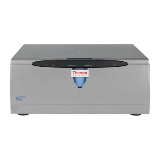
- Page 1 Dionex ICS Series Photodiode Array Detector Operator’s Manual Document No. 065378 Revision 01 January 2012...
- Page 2 © 2012 Thermo Fisher Scientific Inc. All rights reserved. BioLC and Chromeleon are registered trademarks of Thermo Fisher Scientific Inc. in the United States. Adobe, Adobe Reader, and Acrobat are registered trademarks of Adobe Systems Incorporated in the United States and other countries. Microsoft, Windows, and Windows Vista are registered trademarks of Microsoft Corporation in the United States and other countries.
-
Page 3: Table Of Contents
Contents 1 • Introduction ..........1 Detector Overview . - Page 4 Dionex PDA Operator’s Manual Chromatography Software ........27 2.7.1 Overview .
- Page 5 Contents No Detector Response ........74 Noisy Baseline .
- Page 6 Dionex PDA Operator’s Manual A • Specifications .........105 Electrical .
- Page 7 Contents Installing the USB Device Drivers ......124 B.10 Configuring the Dionex PDA in Chromeleon ....125 B.10.1 Using the USB Auto Configuration Wizard .
- Page 8 Dionex PDA Operator’s Manual Doc. 065378-01 1/12...
-
Page 9: Introduction
PDA) (P/N 074114) is an optical chromatography detector capable of measuring absorbance signals and absorbance spectra from 190 to 800 nm. The Dionex PDA can be used with the following Thermo Scientific Dionex systems: the ICS-5000 (analytical systems only), ICS-2100, ICS-1600, ICS-1100, and ICS-900 (as well as some legacy systems). -
Page 10: Theory Of Photodiode Array Detection
6.8 Chromatography Data System. Chromeleon 7 and Chromeleon 6.8 also provide data acquisition and data processing functions. ® NOTE Thermo Scientific Dionex Chromeleon Xpress software can provide real-time control and monitoring of the detector, but does not include data management capabilities. -
Page 11: Advantages Of Photodiode Array Detection
1 • Introduction 1.2.1 Advantages of Photodiode Array Detection Photodiode array detectors are useful in both research and quality assurance laboratories. In the research laboratory, the photodiode array detector provides the analyst with a variety of approaches to the analysis. In the quality assurance laboratory, the photodiode array detector provides several results from a single analysis, thereby increasing the throughput of the HPLC. - Page 12 Dionex PDA Operator’s Manual spectra are automatically collected as each peak elutes. The detector software compares the spectra with those stored in a library to determine the best fit matches; this method increases the likelihood of correctly identifying peaks. For example, Figure 1-2 shows an overlay of pyrene and an impurity obtained from two consecutive chromatographic analyses.
- Page 13 1 • Introduction Impurity Pyrene Figure 1-3. Spectra of Pyrene and an Impurity Doc. 065378-01 1/12...
-
Page 14: Operator's Manual Overview
Dionex PDA Operator’s Manual Operator’s Manual Overview The electronic version (i.e., the PDF file) of this manual contains numerous hypertext links that can quickly take you to other locations within the file. These links include: • Table of contents entries •... -
Page 15: Safety And Regulatory Information
1 • Introduction Safety and Regulatory Information The Dionex PDA was manufactured by Thermo Fisher Scientific at the following location: 527 Lakeside Drive, Sunnyvale, CA 94088-3603 U.S.A. The Dionex ® PDA is designed for use with IC (ion chromatography), BioLC (biocompatible liquid chromatography), and HPLC (high-performance liquid chromatography) systems and should not be used for any other purpose. - Page 16 Dionex PDA Operator’s Manual Signale une situation de danger potentiel qui, si elle n'est pas évitée, pourrait entraîner des blessures graves à mortelles. Signale une situation de danger potentiel qui, si elle n'est pas évitée, pourrait entraîner des blessures mineures à modérées. Également utilisé...
-
Page 17: Safety Labels
1 • Introduction 1.4.2 Safety Labels These symbols appear on the Dionex PDA or on Dionex PDA labels. Alternating current Primary protective conductor terminal Secondary protective conductor terminal Power supply is on Power supply is off Indicates a potential hazard. Refer to this operator’s manual for an explanation of the hazard and how to proceed. - Page 18 Dionex PDA Operator’s Manual Doc. 065378-01 1/12...
-
Page 19: Description
2 • Description Front Features Figure 2-1 illustrates the features on the front of the Thermo Scientific Dionex ICS Series Photodiode Array Detector (Dionex PDA). Status Bar Power Button Front Cover Figure 2-1. Dionex PDA Front Features • The status bar provides LEDs (light emitting diodes) that indicate the status of... - Page 20 Dionex PDA Operator’s Manual DEUTERIUM - UV TUNGSTEN - VIS POWER CONNECTED ALARM Figure 2-2. Dionex PDA Status Bar LED Label LED Status Function CONNECTED Lighted The Dionex PDA is connected to a Chromeleon 7 instrument or a Chromeleon 6.8 timebase. The Dionex PDA is not connected to a Chromeleon 7 instrument or a Chromeleon 6.8 timebase.
-
Page 21: Inside Front Panel
2 • Description Inside Front Panel Grasp the Dionex PDA front cover by the sides and pull it straight off to access the inside front panel (see Figure 2-3). Flow Cell Cover Lamp Cover Leak Sensor Power Button Figure 2-3. Dionex PDA Inside Front Panel •... -
Page 22: Optical System
Dionex PDA Operator’s Manual Optical System Figure 2-4 is a schematic of the Dionex PDA optical system. Light from the tungsten lamp is focused through an opening in the internal structure of the deuterium lamp. Light from the tungsten and deuterium lamps is then focused through the flow cell by the source lens. - Page 23 2 • Description Optical System Function Component Tungsten Lamp The light source for visible and near-infrared wavelengths (380 to 800 nm). The tungsten lamp is focused through an opening in the internal structure of the deuterium lamp; this allows the lamps to share the optical axis to the source lens.
-
Page 24: Flow Cells
Dionex PDA Operator’s Manual 2.3.1 Flow Cells Table 2-1 lists the flow cells available for use with the Dionex PDA. STANDARD FLOW CELLS Cell Material Cell Cell Path Volume of Heat Intended Flow Volume Length Exchanger + Rate Range Inlet Tubing PEEK 13 L 10 mm... - Page 25 2 • Description Do not use a PEEK flow cell with normal phase or chlorinated solvents; these solvents will damage the cell. Do not use a stainless steel flow cell with low pH solutions; these solutions may cause corrosion, contamination, and metal leaching. Standard Flow Cell The standard flow cell assembly (see Figure...
- Page 26 Dionex PDA Operator’s Manual Semi-Micro Flow Cell The semi-micro flow cell assembly (see Figure 2-6) is available in PEEK and 316 stainless steel. Two built-in heat exchangers—one on the cell inlet tubing and one on the cell handle—help stabilize the temperature of the mobile phase before it enters the cell.
- Page 27 2 • Description Semi-Preparative Flow Cell The semi-preparative flow cell assembly (see Figure 2-7) is available in PEEK only. The cell is designed for use with semi-preparative flow applications and flow rates of 5.0 to 100.0 mL/min. The 0.4-mm path length minimizes detector absorbance for concentrated peaks.
-
Page 28: Electronics
Dionex PDA Operator’s Manual Electronics Do not attempt to access the Dionex PDA electronics. The components on the PC boards cannot be serviced by the user. If servicing is required, it must be performed by qualified personnel and appropriate electrostatic discharge (ESD) handling procedures must be followed. - Page 29 2 • Description Lamp Power Supply Board The lamp power supply controls the deuterium and tungsten lamps. In addition, it supplies power to the variable speed fan that cools the optical bench. NOTE The fan speed is controlled automatically. Changes in fan speed may be audible, especially when the lamp selection is changed or the ambient temperature fluctuates.
-
Page 30: Rear Panel
Dionex PDA Operator’s Manual Rear Panel Figure 2-8 illustrates the rear panel of the Dionex PDA. Analog Outputs (4) Drain Tube Connector Relay/TTL Connectors USB Connector Fuse Holder Power Entry Figure 2-8. Dionex PDA Rear Panel Connectors ANALOG OUTPUT The four analog outputs are standard female BNC connectors. The output range is 0 to 1 volt. - Page 31 2 • Description Connectors RELAY/TTL TTL inputs control the following detector functions: autozero (TTL1), UV lamp on/off (TTL3), and visible lamp on/off (TTL4). The TTL2 input is reserved. The two TTL outputs and two relay outputs can be programmed as part of a Chromeleon 7 instrument method or Chromeleon 6.8 program (see Section 3.3.2),...
- Page 32 Dionex PDA Operator’s Manual Operation at AC input levels outside of the specified operating voltage range may damage the Dionex PDA. DANGER D'ÉLECTROCUTION—Pour éviter toute électrocution, il faut utiliser une prise de courant avec prise de terre. Ne l'utilisez pas et ne le branchez pas au secteur C.A.
-
Page 33: Operating Guidelines
2 • Description Operating Guidelines 2.6.1 Mobile Phases Solvent quality significantly affects both detection limits and instrument performance. To ensure optimal performance of the Dionex PDA, observe the following precautions. Strong bases can etch the fused silica windows of the flow cell. If the mobile phase is a base, make sure the mobile phase concentration does not exceed 0.1 M. -
Page 34: Solvent Delivery System
Dionex PDA Operator’s Manual 2.6.2 Solvent Delivery System • The pumping system should deliver continuous flow while maintaining a consistent mobile phase composition (if gradient elution is used). Fluctuations in system backpressure may cause baseline disruptions. High sensitivity applications require a smooth, low-pulsation pump pressure output. -
Page 35: Chromatography Software
2 • Description To clean the pump and system between applications: 1. Remove the column and the suppressor (if installed). 2. Connect the line exiting the injection valve directly to the flow cell inlet tubing. 3. Flush the system with deionized water at 1.0 mL/min for 20 minutes. 4. - Page 36 Dionex PDA Operator’s Manual functions. The UV_Vis tab provides access to Dionex PDA functions, as well as detailed status and diagnostics information. Figure 2-9 shows the Dionex PDA ePanel in Chromeleon 7. Figure 2-9. Example Dionex PDA ePanel in Chromeleon 7 Doc.
- Page 37 2 • Description Figure 2-10 shows the Dionex PDA Control panel in Chromeleon 6.8. Figure 2-10. Example Panel Tabset in Chromeleon 6.8 Two modes of software control are available: direct control and automated control. • With direct control, you select operating parameters and commands from the Chromeleon 7 ePanels (or Command window) or the Chromeleon 6.8 Control panels (or Commands dialog box).
-
Page 38: Data Acquisition License
Dionex PDA Operator’s Manual 2.7.2 3D Data Acquisition License To take full advantage of the Dionex PDA’s capabilities, order Chromeleon with the 3D Data Acquisition license. This license is required in order to perform 3D data presentation and spectral analysis (real-time or post-run), peak purity analysis with selectable criteria, and spectral library search for positive peak identification. - Page 39 2 • Description • Leak detection • Wavelength verification System Wellness and Predictive Performance commands and parameters are available in the Chromeleon 7 Command window or the Chromeleon 6.8 Commands dialog box. Doc. 065378-01 1/12...
- Page 40 Dionex PDA Operator’s Manual Doc. 065378-01 1/12...
-
Page 41: Operation And Maintenance
3 • Operation and Maintenance Getting Started 3.1.1 Initial Startup 1. If you are starting the Thermo Scientific Dionex ICS Series Photodiode Array Detector (Dionex PDA) for the first time, press the main power switch on the rear panel (see Figure 2-8). -
Page 42: Connect To The Chromeleon 7 Client
Dionex PDA Operator’s Manual 3.1.2 Connect to the Chromeleon 7 Client 1. Start the Instrument Controller Service, if it is not already running. If the Chromeleon tray icon on the taskbar is crossed out in red the Instrument Controller Service is not running. To start it, right- click the icon and select Start Chromeleon Instrument Controller. -
Page 43: Connect To The Chromeleon 6.8 Client
3 • Operation and Maintenance Figure 3-1. Example Dionex PDA ePanel in Chromeleon 7 3.1.3 Connect to the Chromeleon 6.8 Client 1. Start the Chromeleon server, if it is not already running. If the Chromeleon server icon on the taskbar is crossed out in red , the server is not running. - Page 44 Dionex PDA Operator’s Manual b. Select View > Default Panel Tabset or click the corresponding toolbar button to display the panel tabset. c. To display the Dionex PDA Control panel, select the Dionex PDA tab on the panel tabset (see Figure 3-1).
-
Page 45: Turn On The Lamps
3 • Operation and Maintenance 3.1.4 Turn On the Lamps To turn on the lamps, click UV Lamp and Vis Lamp on the Chromeleon 7 ePanel (see Figure 3-1) or the Chromeleon 6.8 Control panel (see Figure 3-2). When a detector lamp is turned on for the first time after the detector power is turned on, wavelength calibration is performed automatically. -
Page 46: Routine Operation
Dionex PDA Operator’s Manual • Create and run an equilibration instrument method or program to automate the process. See Section 3.3.2 for details about automated control. • If you are running Chromeleon, you can use the Smart Startup feature to automate system startup and equilibration. - Page 47 3 • Operation and Maintenance 3. If the function that you want to perform is not available from the panel, open the Command window (see the instructions below) or the Commands dialog box (see page 40). The commands available in the Command window or Commands dialog box vary, depending on these variables: •...
- Page 48 Dionex PDA Operator’s Manual 3. Click UV and then click the Properties tab or Commands tab to view detector properties or commands, respectively. To execute a command, click the button next to the command. NOTE To change the display filter level, right-click the list of commands and select the desired filter on the context menu.
-
Page 49: Automated Control
3 • Operation and Maintenance 3.3.2 Automated Control You can control the detector automatically by running instrument methods (in Chromeleon 7) or programs (in Chromeleon 6.8) that specify the function the detector and other system instruments should perform at a specific time. - Page 50 Dionex PDA Operator’s Manual Factory Default Settings The Dionex PDA outputs four analog signals at all times, even when the detector is not interfaced to a computer. Data is presented at the analog output channels whenever the detector power is on. A chart recorder or other voltage-measuring device can be used to monitor the channels.
-
Page 51: Optimizing Detector Performance
3 • Operation and Maintenance Optimizing Detector Performance The performance of the Dionex PDA can be optimized by careful selection of key operating parameters. This section defines these parameters, describes how they interact, and offers guidelines for selecting them. The table below summarizes the topics discussed in this section. - Page 52 Dionex PDA Operator’s Manual Do not use a stainless steel flow cell with low pH solutions; these solutions may cause corrosion, contamination, and metal leaching. Rise Time Rise time is a measure of how quickly the Dionex PDA responds to a change in signal.
- Page 53 3 • Operation and Maintenance Data Collection Rate The data collection rate (or sample rate) is the number of data points per second (Hz) at which the computer stores data from the Dionex PDA. (The detector electronics collect data at up to 20.0 Hz.) The Dionex PDA data collection rate settings are 0.25, 0.5, 1.0, 2.0, 2.5 (default), 5.0, 10.0, or 20.0 Hz.
- Page 54 Dionex PDA Operator’s Manual Sample Wavelength The Dionex PDA measures absorbance over all wavelengths from 190 to 800 nm. The deuterium lamp optimizes the UV range (190 to 380 nm), while the tungsten lamp optimizes the visible range (380 to 800 nm). Set the sample wavelength at the wavelength with the absorbance maxima for the analytes of interest.
- Page 55 3 • Operation and Maintenance 0.0400 WVL:254 nm 0.0300 Bandwidth = 8 0.0200 Noise = 14 0.0100 0.0000 Bandwidth = 4 Noise = 16 AU -0.0100 -0.0200 -0.0300 Bandwidth = 1 Noise = 26 -0.0400 -0.0500 0.00 0.50 1.00 1.50 2.00 2.50 3.00...
- Page 56 Dionex PDA Operator’s Manual If the sample wavelength is 372 nm, you might select a reference wavelength of 425 nm because both wavelengths are within the visible spectrum (380 to 800 nm) of the tungsten lamp. Select a reference wavelength and reference bandwidth in a quiet area of the spectrum where little absorption occurs.
- Page 57 3 • Operation and Maintenance The operating conditions are: Sample wavelength = 520 nm Bandwidth = 10 nm Reference bandwidth = 50 nm (active reference mode only) Flowing water at 1.0 mL/min, 10.35 MPa (1500 psi) Reference Wavelength Mode: “Off” Baseline Drift: -120 AU/hour Reference Wavelength Mode: “Active”...
- Page 58 Dionex PDA Operator’s Manual Reference Bandwidth The reference bandwidth is analogous to the conventional bandwidth of a channel. The purpose of the reference bandwidth is to average several photodiode signals in a range surrounding the reference wavelength. It is not necessary to select a reference bandwidth unless you enter a reference wavelength (i.e., you select the active reference mode).
- Page 59 3 • Operation and Maintenance These settings calculate the absorbance by the following equation: avg I 300 to 350 -------------------------------------------------- - offset in AU (at autozero at 272 nm) AU = log – avg I 270 to 274 Where: = Light intensity Offset = Absorbance offset at autozero 1.02 1200...
- Page 60 Dionex PDA Operator’s Manual Step (Chromeleon 6.8 only) It is not necessary for the user to select a step setting; the appropriate step setting is selected automatically by Chromeleon 6.8. A step is the time interval between two successively stored data points. The smaller the step, the more data points that are recorded and, in general, the more precise the analytical results.
- Page 61 3 • Operation and Maintenance step determines the sampling rate at which the detector stores spectra. Ideally, the step is no smaller than the interval suggested for the rise time (see the table in “Data Collection Rate” on page 45). The advantage of a larger step size is that it reduces the amount of data stored;...
- Page 62 Dionex PDA Operator’s Manual Negative Approximate Negative Approximate Negative Approximate Negative Absorbance Absorbance at 210 nm Absorbance at 240 nm Absorbance at 254 nm Level –2200 mAU –50 mAU –300 mAU 1 (default) –2300 mAU –100 mAU –350 mAU –2600 mAU –200 mAU –450 mAU –2600 mAU...
-
Page 63: Shutdown
3 • Operation and Maintenance Shutdown Before shutting down the Dionex PDA for more than 24 hours, flush the system with deionized water or methanol for at least 15 minutes at 1.0 mL/min (or maintain a continuous flow at 0.2 mL/min). This rinses corrosive acids, salts, or bases from the flow paths. - Page 64 Dionex PDA Operator’s Manual Without the column, backpressure is usually less than 0.34 MPa (50 psi), depending on the flow rate and tubing ID. Note that the semi-micro flow cell will develop approximately 1.03 MPa (150 psi) backpressure at 1.0 mL/min. If the backpressure remains high, remove the fittings and tubing from part of the flow path, section by section;...
- Page 65 3 • Operation and Maintenance 4. After calibrating the lamp, check the intensity again. If the reading is still too low, follow the steps in Section 4.7 to resolve the problem. • Run the wavelength verification test for both the deuterium and tungsten lamps approximately every 6 months (see Section 4.14.2).
- Page 66 Dionex PDA Operator’s Manual Doc. 065378-01 1/12...
-
Page 67: Troubleshooting
4 • Troubleshooting This chapter is a guide to troubleshooting problems that may occur while operating the Thermo Scientific Dionex ICS Series Photodiode Array Detector (Dionex PDA): • Section 4.1 describes error messages and how to troubleshoot them. • Section 4.2 through Section 4.14... - Page 68 Dionex PDA Operator’s Manual The table below lists the Dionex PDA-related error messages and their default severity levels. For troubleshooting assistance, refer to the page indicated in the table. Dionex PDA-Related Alarms and Error Conditions Default Severity Level 3DFIELD RefWavelength and/or RefBandwidth is out of Error page 62 range.
- Page 69 4 • Troubleshooting Dionex PDA-Related Alarms and Error Conditions Default Severity Level The minimum wavelength must be less than the Error page 69 maximum wavelength. Min wavelength = x; max wavelength = x. The range of wavelength bunching is 1 to 25 nm. Error page 69 The range of wavelengths is outside the 190 to 800 nm...
- Page 70 Dionex PDA Operator’s Manual 3DFIELD RefWavelength and/or RefBandwidth is out of range. To troubleshoot: For all data collection rates other than 20 Hz, select parameters that meet the following criteria: λ Where: = Reference wavelength BW = Reference bandwidth For example, the following parameters are VALID: Wavelength = 190 to 800 nm Reference wavelength = 750 nm Reference bandwidth = 50 nm...
- Page 71 4 • Troubleshooting When the data collection rate is 20 Hz, select parameters that meet the following criteria: Minimum Maximum Maximum Minimum Where: = Reference wavelength BW = Reference bandwidth For example, the following parameters are VALID: Wavelength = 190 to 500 nm Reference wavelength = 450 nm Reference bandwidth = 50 nm These parameters are valid because 190 to 500 nm is a range of 310 nm and...
- Page 72 Dionex PDA Operator’s Manual Autozero is already in progress. To troubleshoot: This message appears if you select Autozero (in the Chromeleon 7 Command window or the Chromeleon 6.8 Commands dialog box) when the autozero routine is already in progress. Allow the autozero routine to continue running until completion.
- Page 73 4 • Troubleshooting Can’t execute calibration command during data acquisition. Can’t execute diagnostic command during data acquisition. Can’t execute x command during data acquisition. To troubleshoot: During data acquisition, no other commands can be executed. Wait until data acquisition is completed before attempting to issue any other command. Command not executed because an Autozero command is already running.
- Page 74 Dionex PDA Operator’s Manual Diagnostic is running. To troubleshoot: This message appears if you attempt to issue a command or select a parameter while a diagnostic routine is running. Wait until the diagnostic routine is completed before making any changes. DSP communication failure.
- Page 75 4 • Troubleshooting b. Select UV, and then select LampIntensity. The intensity reading should be above 10 million counts for a standard or semi- preparative cell or above 3 million counts for a semi-micro cell. If the reading is acceptable, resume normal operation. If the reading is too low, see Section 4.7.
- Page 76 Dionex PDA Operator’s Manual Leak sensor error. To troubleshoot: Locate the source of the leak and tighten (or replace) the liquid line connection. For tightening requirements, refer to Installation of Dionex Liquid Line Fittings (Document No. 031432). The manual is on the Thermo Scientific Reference Library DVD (P/N 053891).
- Page 77 4 • Troubleshooting PDA is running a calibration or diagnostic function. Not ready to accept this command. To troubleshoot: Wait until the calibration procedure or diagnostic routine finishes running before attempting to issue any command. The minimum wavelength must be less than the maximum wavelength.
- Page 78 Dionex PDA Operator’s Manual UV lamp error. UV lamp error or control circuitry error while lamp is on. UV lamp failed to turn on for the required operation. UV lamp error while attempting to turn on. Visible lamp error. Visible lamp error or control circuitry error while lamp is on. Visible lamp error while attempting to turn on.
- Page 79 4 • Troubleshooting If the deuterium lamp has been in operation for more than 2000 hours, replace it (see Section 5.7). If the error message appears again, contact Thermo Fisher Scientific for assistance. If the deuterium lamp has been in operation for less than 2000 hours, turn off the lamp for at least 3 minutes and then turn it on again.
- Page 80 Dionex PDA Operator’s Manual UV lamp control circuitry error while lamp is off. UV lamp error while attempting to turn off. Visible lamp control circuitry error while lamp is off. Visible lamp error while attempting to turn off. To troubleshoot: The lamp power supply may have failed or the CPU board may have failed.
-
Page 81: Alarm Led Is Lighted
4 • Troubleshooting ALARM LED Is Lighted The leak sensor in the drip tray may have been triggered. Check the Chromeleon Audit Trail for a leak-related error message. Find and eliminate the source of the leak. After fixing the leak and drying the sensor, clear the LED. -
Page 82: No Detector Response
Dionex PDA Operator’s Manual No Detector Response • Detector power not on Check that the power cord is connected from the Dionex PDA rear panel to a power source. Check that the main power switch on the rear panel is turned on. Check the fuses and replace them, if necessary (see Section 5.9). -
Page 83: Noisy Baseline
4 • Troubleshooting Noisy Baseline • Mobile phase or post-column reagent contains light-absorbing impurities Prepare all mobile phases and reagents with spectro-grade solvents, reagent- grade chemicals, and ASTM Type I (or better) filtered, deionized water that meets the specifications in Table B-1. - Page 84 Dionex PDA Operator’s Manual • Connect a backpressure line to the cell (see Section B.3). This increases the backpressure on the cell, thereby shrinking bubbles and allowing them to pass more easily through the cell. • Contaminants in flow cell Clean the cell (see Section 5.2).
- Page 85 4 • Troubleshooting • Front cover, lamp cover, or flow cell cover is missing Optical components are sensitive to temperature and light. Do not operate the Dionex PDA unless the front cover, lamp cover, and flow cell cover are in place.
-
Page 86: Drifting Baseline
Dionex PDA Operator’s Manual Drifting Baseline • Fluctuations in ambient temperature Make sure the Dionex PDA installation site temperature remains consistent. Allow at least 6 cm (2.4 in) of clearance behind the Dionex PDA for ventilation. Check that the flow cell inlet tubing is routed through the heat exchanger (see Figure 2-5) and is correctly connected to the inside front panel (see Figure... -
Page 87: Deuterium Lamp Intensity Reading Too Low
4 • Troubleshooting • Absorbance in the reference wavelength Sample absorbance in the selected reference wavelength may cause excessive baseline drift. Select a reference wavelength and reference bandwidth in an area of the spectrum where little absorption occurs (see “Reference Bandwidth”... -
Page 88: Wavelength Calibration Fails
Dionex PDA Operator’s Manual Reinstall the cell in the optical bench. g. Autozero the detector again to verify that the problem has been resolved. If the error message appears again, contact Thermo Fisher Scientific for assistance. If the lamp intensity reading is below 10 million counts for a standard or semi-preparative cell or below 3 million counts for a semi-micro cell, follow these steps: a. - Page 89 4 • Troubleshooting procedures. If the detector fails the wavelength calibration again, contact Thermo Fisher Scientific for assistance. • Deuterium lamp intensity out of calibration 1. Remove the cell from the optical bench (see Section 5.4). 2. Check the deuterium lamp intensity: a.
-
Page 90: Wavelength Verification Fails
Dionex PDA Operator’s Manual • Flow cell contains air bubble or old mobile phase Flush the cell with the mobile phase for the application. • Cell not clear Clean the cell (see Section 5.2). If the detector fails the wavelength calibration again, replace the flow cell windows (see Section 5.5). -
Page 91: No Spectra Collected
4 • Troubleshooting 4.10 No Spectra Collected • Spectral range was not programmed In Chromeleon 7, select a spectral range in the instrument method or on the Dionex PDA ePanel. In Chromeleon 6.8, select a spectral range in the program or on the Dionex PDA Control panel. -
Page 92: Peaks Too Large Or Small
Dionex PDA Operator’s Manual 4.12 Peaks Too Large or Small • Analog output-related problem Check the recorder and integrator input voltage. The Dionex PDA provides a 1 volt full-scale output. Verify that the selected output range (AU full-scale) is appropriate. •... - Page 93 4 • Troubleshooting • Incorrect reference wavelength selected Select a different reference wavelength. For guidelines to follow when selecting the reference wavelength, see page • Bandwidth too wide Select a bandwidth that provides the resolution required to achieve the desired sensitivity.
-
Page 94: Faulty Usb Communication
Dionex PDA Operator’s Manual 4.14 Faulty USB Communication • Dionex PDA not recognized by Windows operating system Thermo Fisher Scientific strongly recommends installing Chromeleon before connecting the Dionex PDA to the computer. When the chromatography software is installed first, USB driver information is loaded automatically. If Windows fails to detect the Dionex PDA, refer to the following table for corrective action. -
Page 95: Moduleware Run-Time Diagnostics
4 • Troubleshooting 4.14.1 Moduleware Run-Time Diagnostics The Dionex PDA Moduleware periodically checks the status of certain system parameters. All problems are reported to the computer and logged in the Chromeleon Audit Trail. The Audit Trail includes the date, time, and severity level for each problem the Dionex PDA reports. - Page 96 Dionex PDA Operator’s Manual • Wavelength calibration Purpose: Improves wavelength accuracy in the UV range by reassigning new wavelengths to each pixel, based on the emission spectrum from the deuterium lamp. The detector will perform the wavelength calibration routine and upload the result (pass or fail) to Chromeleon.
- Page 97 4 • Troubleshooting In Chromeleon 6.8: a. To open the Wellness panel, click the Wellness button on the Dionex PDA Control panel. b. Click the wavelength verification script button under Diagnostics. Doc. 065378-01 1/12...
- Page 98 Dionex PDA Operator’s Manual Doc. 065378-01 1/12...
-
Page 99: Service
5 • Service This chapter describes routine service procedures for the Thermo Scientific Dionex ICS Series Photodiode Array Detector (Dionex PDA) that users may perform. All procedures not described here, including electronics-related repair procedures, must be performed by Thermo Fisher Scientific personnel. For assistance, contact Technical Support for Dionex products. - Page 100 Dionex PDA Operator’s Manual Table 5-2. Dionex PDA with Standard Cell (Continued) Component PEEK Cell SST Cell Cell inlet tubing: 0.25-mm (0.010-in) ID P/N 056124 Cell outlet tubing: 0.25-mm (0.010-in) ID P/N 051650 Reducing union fittings P/N 055903 P/N 055902 Ferrules P/N 043276 P/N 010262...
-
Page 101: Cleaning The Flow Cell
5 • Service Cleaning the Flow Cell Film deposits on the flow cell windows may cause excessive baseline noise or high absorbance offset. 1. Pump methanol through the cell for 20 to 30 minutes at 1.0 mL/min. 2. Pump deionized water through the cell for 20 to 30 minutes at 1.0 mL/min. If the procedure above does not clean the cell, follow these steps: 1. -
Page 102: Removing The Flow Cell From The Optical Bench
Dionex PDA Operator’s Manual Removing the Flow Cell from the Optical Bench The flow cell must be removed from the optical bench in order to inspect the cell for leaks or obstructions, replace the cell windows (see Section 5.5), or install a new cell (see Section 5.6). -
Page 103: Replacing The Flow Cell Windows
5 • Service Replacing the Flow Cell Windows Contaminated flow cell windows can significantly increase baseline noise and cause wavelength calibration to fail. If cleaning the cell (see Section 5.2) does not eliminate these problems, replace both windows. NOTE The windows in the semi-preparative flow cell cannot be replaced. - Page 104 Dionex PDA Operator’s Manual Cell Outlet Tubing Cell Inlet Tubing O-Ring Groove O-Ring (P/N 054136) Window (P/N 054135) Flow Cell Retaining Nut (P/N 054133) Figure 5-2. Replacing the Standard or Semi-Micro Flow Cell Windows (Light inlet side shown) 6. Check the groove to be sure it does not contain any dust or dirt particles, and then install a new O-ring (P/N 054136).
-
Page 105: Replacing The Flow Cell
5 • Service If tightening the retaining nut(s) stops the leakage, dry the cell thoroughly with a lint-free, optical-grade tissue and go on to Step If tightening the retaining nut(s) does not stop the leakage, remove the window and inspect the O-ring and groove for the cause of the leak: •... -
Page 106: Replacing The Deuterium Lamp
Dionex PDA Operator’s Manual Replacing the Deuterium Lamp 1. Stop the Chromeleon instrument controller or server. 2. Press the power button on the front of the Dionex PDA to turn off the power. 3. Turn off the main power switch on the Dionex PDA rear panel. The deuterium lamp emits UV radiation that is harmful to the eyes. - Page 107 5 • Service 9. Squeeze the clip on the UV lamp connector and disconnect it from the 6-pin bulkhead connector on the side wall (see Figure 5-3). Figure 5-3. Lamp Connections 10. Loosen the three screws in the deuterium lamp flange (see Figure 5-3) and pull the lamp out of the optical bench.
- Page 108 Dionex PDA Operator’s Manual 15. Replace the lamp cover. Do not pinch the UV lamp connector wires under the lamp cover. 16. Thread the flow cell inlet tubing through the tubing guide on the lamp cover and reinstall the tubing bracket. 17.
-
Page 109: Replacing The Tungsten Lamp
5 • Service Replacing the Tungsten Lamp 1. Stop the Chromeleon instrument controller or server. 2. Press the power button on the front of the Dionex PDA to turn off the power. 3. Turn off the main power switch on the Dionex PDA rear panel. The lamp housing and base may be hot to the touch, especially after the lamp has been in operation for a long time. - Page 110 Dionex PDA Operator’s Manual 12. Carefully insert the new lamp into the optical bench and tighten the three screws that secure the lamp to the optical bench. (The replacement lamp is pre-aligned in the mount.) To ensure proper performance, the lamp must be fully seated. 13.
-
Page 111: Replacing The Main Power Fuses
5 • Service Replacing the Main Power Fuses HIGH VOLTAGE—Disconnect the main power cord from its source and also from the rear panel of the Dionex PDA. HAUTE TENSION—Débranchez le cordon d'alimentation principal de sa source et du panneau arrière du Dionex PDA. HOCHSPANNUNG—Ziehen Sie das Netzkabel aus der Steckdose und der Netzbuchse auf der Rückseite des Dionex PDA. - Page 112 Dionex PDA Operator’s Manual 5. Replace the two fuses in the holder with new 4.0 amp fast-blow IEC 127 fuses (P/N 954763). Thermo Fisher Scientific recommends always replacing both fuses. 6. Reinsert the fuse holder into the compartment. (The fuse holder is keyed to fit only in the correct orientation.) Apply pressure evenly against the holder until the locks are engaged.
-
Page 113: A • Specifications
A • Specifications A.1 Electrical Main Power 85 to 265 VAC, 47 to 63 Hz (auto-sensing; no manual adjustment required) Typical input power: 100 W Maximum line draw: 3.5 A at 110 VAC at power-up Two fast-blow IEC 127 fuses (P/N 954763) rated at 4.0 A Fuses A.2 Physical Dimensions... -
Page 114: Detector
Dionex PDA Operator’s Manual A.4 Detector Optical System Single-beam, reverse-optics design with concave holographic grating Light Sources Deuterium lamp (30 W) for ultraviolet spectrum analysis Tungsten lamp (15 W) for visible spectrum analysis Both lamps: Lifetime of 2000 hours with >50% of initial intensity Photodiode Array 1024-element photodiode array bench... -
Page 115: Flow Cells
A • Specifications A.5 Flow Cells A.5.1 Standard Flow Cell Cell Body PEEK or 316 stainless steel Volume and PEEK cell: 13 L volume; 10 mm (0.394 in) path length Optical Path Stainless steel cell: 13 L volume; 10 mm (0.394 in) path length Length Maximum PEEK cell: 2 MPa (300 psi) -
Page 116: Semi-Preparative Flow Cell
Dionex PDA Operator’s Manual • Chemical Do not use bases stronger than 0.1 M; these solutions will Compatibility etch the fused silica windows of the flow cell. • Do not use normal phase or chlorinated solvents with the PEEK flow cell; these solutions will damage the cell. •... - Page 117 A • Specifications Volume of Semi- PEEK cell: 5 L Micro Cell Heat Stainless steel cell: 5 L Exchangers (including cell inlet tubing) Doc. 065378-01 1/12...
- Page 118 Dionex PDA Operator’s Manual Doc. 065378-01 1/12...
-
Page 119: B • Installation
B • Installation B.1 Facilities Requirements • Make sure the installation site for the Thermo Scientific Dionex ICS Series Photodiode Array Detector (Dionex PDA) meets the power and environmental specifications listed in Appendix • For mobile phase generation, or when manually preparing mobile phase and... -
Page 120: Unpacking
The Dionex PDA can be positioned in many locations within a system; the options include: Above a Dionex ICS-5000 Thermal Compartment Below a Thermo Scientific Dionex AS-AP Autosampler On either side of an integrated system (for example, the Dionex ICS-2100 Ion Chromatography System) •... -
Page 121: Installing The Flow Cell
B • Installation B.3 Installing the Flow Cell Do not touch the cell windows. If you touch a window, clean it with isopropyl alcohol (IPA) and a clean lens tissue. Do not use a PEEK flow cell with normal phase or chlorinated solvents;... - Page 122 Dionex PDA Operator’s Manual Cell Outlet Tubing Reducing Union Fitting (PEEK cell: P/N 055903; Stainless steel cell: P/N 055902) Cell Inlet Tubing Handle Reducing Union Fitting (PEEK cell: P/N 055903; Stainless steel cell: P/N 055902) Flow Cell Heat Exchangers Spring Clip Figure B-1.
- Page 123 B • Installation 10. Connect a backpressure line to the cell outlet. The backpressure line will provide enough restriction to generate the small amount of backpressure (0.14 to 0.34 MPa; 20 to 50 psi) required to help prevent bubbles from forming in the cell.
-
Page 124: Connecting The Waste Line
Dionex PDA Operator’s Manual B.4 Connecting the Waste Line Connect the waste line (P/N 055075) to the Dionex PDA rear panel (see Figure B-3). Place the free end of the waste line in a waste container below the level of the workbench on which the Dionex PDA is installed. The drain tube must remain below the drain port. -
Page 125: Connecting The Relays/Ttls (Optional)
B • Installation B.6 Connecting the Relays/TTLs (Optional) Connection of relay loads and their power sources to the TTL outputs will damage the TTL output stage. If the relay load can source more than 200 mA at 5V or higher, it may damage the Data Processing board. -
Page 126: Connecting To The Chromeleon Pc
Dionex PDA Operator’s Manual The table below describes the pin assignments for the relay and TTL connector. Relays 1 and 2 can be configured in Chromeleon to switch any low-voltage control. The switched current must be less than 200 mA and 42 V peak. -
Page 127: Chromeleon 7: Starting The Instrument Controller Service
B • Installation If installation is required, follow the instructions in the appropriate installation guide. The guides are provided on the Thermo Scientific Reference Library DVD (P/N 053891). • For Chromeleon 7, refer to Chromeleon 7 Installation Guide. • For Chromeleon 6.8, refer to Installing the Chromeleon Chromatography Management System with a Dionex Ion Chromatograph (Document No. -
Page 128: Connecting The Usb Cable
Dionex PDA Operator’s Manual B.7.4 Connecting the USB Cable Select one of the following methods to connect the Dionex PDA to the Chromeleon computer: • Connect the detector directly to a USB port on the PC. • Connect the detector to the internal USB hub of another module in the system, and connect the other module directly to the PC. - Page 129 B • Installation To connect the Dionex PDA to the internal USB hub of another module: NOTE If you are installing a Dionex PDA with a Dionex ICS-5000 or Dionex ICS-3000 Ion Chromatography System, refer to the system installation instructions for information about USB compatibility issues with these systems.
- Page 130 Dionex PDA Operator’s Manual To connect the Dionex PDA to an external USB hub: The Dionex PDA Ship Kit (P/N 060977) contains one USB cable (P/N 063246). Contact Thermo Fisher Scientific to order the external USB hub (P/N 060392) and additional USB cable (P/N 063246) required for this configuration.
-
Page 131: Connecting The Power Cord
B • Installation B.8 Connecting the Power Cord 1. Verify that the main power switch on the rear panel of the Dionex PDA is turned off. (The main power switch may be turned on accidentally when the detector is unpacked.) 2. -
Page 132: Installing The Usb Device Drivers
Dionex PDA Operator’s Manual B.9 Installing the USB Device Drivers 1. Turn on the computer power. 2. Log onto Windows Vista or Windows XP as an administrator. For a network computer, log on as a user with local computer administrator privileges. -
Page 133: Configuring The Dionex Pda In Chromeleon
For instructions on how to manually create a timebase, refer to the Chromeleon 6.8 Help or to Installing Chromeleon with a Dionex Ion Chromatograph (Document No. 031883). The software installation manuals are provided on the Thermo Scientific Reference Library DVD (P/N 053891) B.10.1 Using the USB Auto Configuration Wizard 1. - Page 134 Dionex PDA Operator’s Manual 4. (Optional) Select the Customize instrument names (For advanced users only) check box (Chromeleon 7) or the Customize timebase names (For advanced users only) check box (Chromeleon 6.8). 5. Click Accept to create a new instrument or timebase. 6.
-
Page 135: Selecting Configuration Properties
B • Installation B.10.2 Selecting Configuration Properties When the Dionex PDA is added to an instrument or timebase, default configuration properties are selected. Verify the default settings for the detector and select other settings as required. 1. To open the configuration properties dialog box, right-click the detector in the instrument or timebase and click Properties. -
Page 136: Starting The Chromeleon Client
Dionex PDA Operator’s Manual B.11 Starting the Chromeleon Client Chromeleon 7 Client 1. Click Start > All Programs > Chromeleon 7 > Chromeleon 7. 2. To display the Chromeleon 7 ePanel Set, click the Instruments Category Bar on the Console. Chromeleon 7 connects to the instrument and displays the ePanel Set. - Page 137 B • Installation 3. To display the Dionex PDA Control panel (see Figure B-10), select the Dionex PDA tab on the panel tabset. The Control panel provides access to Dionex PDA functions, as well as detailed status and diagnostics information. Figure B-10.
- Page 138 Dionex PDA Operator’s Manual Doc. 065378-01 1/12...
-
Page 139: C • Reordering Information
C • Reordering Information Part Number Item 939016T Deuterium lamp 056123T Tungsten lamp 954763 Fuse, 4.0 amps (fast-blow IEC 127) 923686 Relay/TTL connector, 12-pin 043598 Twisted wire assembly, 2 meters (8 ft) 063246 USB cable, 1 m (3 ft) Standard Flow Cell: PEEK 056346 PEEK standard flow cell (with heat exchangers) 057304... - Page 140 Dionex PDA Operator’s Manual Part Number Item 060498 Dionex AD25/Dionex PDA/Dionex PDA-100 Flow Cell Windows Replacement Kit Semi-Micro Flow Cell: 316 Stainless Steel 063884 Stainless steel semi-micro flow cell (with heat exchangers) 051650 Stainless steel semi-micro flow cell outlet tubing assembly 055902 Reducing union fitting (stainless steel) 010262...
- Page 141 Index Numerics Average, 43 Definition, 53 2D data collection, 1 Guidelines for selecting, 53 3D Data Acquisition license, 4, 30 Avertissement icon, 8 Error message, 60, 63 3D data collection 3D Data Acquisition license, 4, 30 Bunch width selection, 51 Reducing data file size, 53 Backpressure, 56 Step time selection, 52...
- Page 142 Dionex PDA Operator’s Manual Backpressure line, 76 ePanel Set, 27 Backpressure line installation, 115 Installation, 119 Chemical compatibility, 43 Instrument method, 41 Cleaning procedure, 93 Overview of automated control, 41 Contaminants, 76 Peak purity analysis, 30 Heat exchangers, 17 – 19, 91, 108 Processing method, 41 Illustration, 17 –...
- Page 143 Index DEUTERIUM - UV LED Filter paddle, 14 – 15 LED is flashing, 12, 73 – 74 Malfunction, 77, 80 LED is lighted, 12, 70 Positions, 15 Deuterium lamp, 14 – 15 Flow cells Calibration, 80 See Cells Intensity, 56 See Type of cell Lamp does not light, 73 Front panel...
- Page 144 Dionex PDA Operator’s Manual Chromeleon 7, 119 Mise en garde icon, 8 Instructions, 117 – 118 Mobile phases, 26 PDA with ICS-3000 system, 121 Concentration guidelines, 16, 25, 43 PDA with ICS-5000 system, 121 Degassing, 25, 75 Site requirements, 105, 111 Effect of pH on retention time, 25 Instrument connections, 74 Lamp stability after changing, 75, 78...
- Page 145 Index Preamp board, 21 Power cord, 23, 103, 123 Repairs, 20 POWER LED LED is lighted, 12 Control panel, 36, 129 Power requirements, 105 Peak height, 44, 46 Power supply, 20 Peak identification, 2 – 3, 46 Preamp board, 21 Peak purity, 2 –...
- Page 146 Dionex PDA Operator’s Manual Reference wavelength, 43, 47 – 48, 50, 78 Chemical compatibility, 108 Definition, 47 Flow rate range, 16 Effect on baseline drift, 48 Heat exchanger volume, 16 Guidelines for selecting, 47 – 48, 50 Operating pressure, 108 Inappropriate setting, 76 Optical path length, 16, 108 Relay control, 23, 117...
- Page 147 Index Stainless steel flow cells, 16 Spectra not collected, 83 Chemical compatibility, 17, 25, 44, 113 Spectral resolution is poor, 83 Corrosion, 17, 25, 44, 107 – 108, 113 USB communication problem, 86 Metal leaching, 17, 25, 44, 108, 113 Wavelength calibration fails, 80 See also Cells Wavelength verification fails, 82...
- Page 148 Dionex PDA Operator’s Manual Verification, wavelength, 88 Visible focus lens, 15 Visible wavelengths, 15 Vorsicht icon, 8 Warning icon, 7 Warnung icon, 8 Warranty, voiding, 91 Waste line, 22 Installation, 116 Wavelength calibration, 2, 82, 88 Causes of failure, 82, 95 Wavelength verification, 15, 82, 88 Wavelengths, single, 1, 46 Reference modes, 47...
Need help?
Do you have a question about the Dionex ICS Series and is the answer not in the manual?
Questions and answers