
Related Manuals for Thermo Scientific gibco CTS Rotea


Summary of Contents for Thermo Scientific gibco CTS Rotea
- Page 1 ™ ™ Rotea Counterflow Centrifugation System Process Design USER GUIDE Catalog Number A44769 Publication Number MAN0018754 Revision A.0 For Research Use or Manufacturing of Cell, Gene, or Tissue- Based Products.
- Page 2 Life Technologies Holdings Pte Ltd | Block 33 | Marsiling Industrial Estate Road 3 | #07-06, Singapore 739256 For descriptions of symbols on product labels or product documents, go to thermofisher.com/symbols-definition. The information in this guide is subject to change without notice. DISCLAIMER: TO THE EXTENT ALLOWED BY LAW, THERMO FISHER SCIENTIFIC INC.
-
Page 3: Table Of Contents
Contents ■ CHAPTER 1 Product information ..........7 Product description . - Page 4 Contents List view ..............39 Step summary .
- Page 5 Contents Elutriation ..............77 Overview .
- Page 6 Contents Water runs ..............116 First run with cells .
-
Page 7: Chapter 1 Product Information
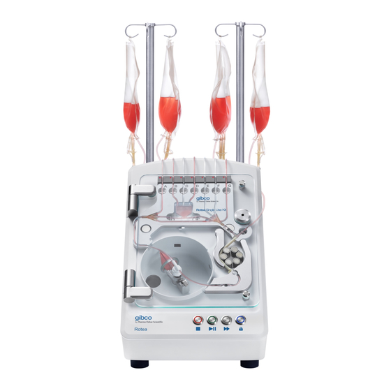
Product information IMPORTANT! Before using this product, read and understand the information in the “Safety” appendix in this document. Product description ™ ™ ™ The Gibco Rotea Counterflow Centrifugation System is an automated, closed-flow benchtop instrument that can perform a wide variety of cell processing steps across different cell types. ™... -
Page 8: System Overview
Chapter 1 Product information System overview System overview ™ ™ Rotea Counterflow Centrifugation Instrument ™ ™ The CTS Rotea Counterflow Centrifugation Instrument is an automated benchtop instrument that incorporates several important features that enable the user to develop and optimize protocols while ensuring the integrity of the process. -
Page 9: Cts ™ Rotea ™ Single-Use Kit
Chapter 1 Product information System overview ™ Rotea ™ Single-Use Kit ™ ™ The CTS Rotea Single-Use Kit can be flexibly configured by the user to perform a range of cell processing applications such as separation, isolation, buffer exchange, wash and concentrate. The Single-Use Kit comprises eight sterile weldable tubes to which the user connects input and output bags/vessels to suit their specific process. -
Page 10: Cts ™ Rotea ™ Graphical User Interface (Gui)
Chapter 1 Product information System overview ™ Rotea ™ Graphical User Interface (GUI) ™ ™ The CTS Rotea Graphical User Interface (GUI) enables users to download and run protocols on the instrument. The ™ Rotea GUI also includes the ability to make in-process adjustments to the G force and flow rate and has an integrated high-resolution color camera to visualize the behavior of cells in the CFC Chamber in real-time. -
Page 11: Rotea Protocol Builder
Chapter 1 Product information System overview Rotea Protocol Builder The Rotea Protocol Builder is a Windows-based application that enables users to download, create, modify and save protocols. ™ Rotea ™ Counterflow Centrifugation System Process Design User Guide... -
Page 12: Chapter 2 Software Installation
Software installation Software installation 1. Prior to installing a new release of the Rotea Protocol Builder application, first un-install any previous versions. ™ Rotea ™ Counterflow Centrifugation System Process Design User Guide... - Page 13 Chapter 2 Software installation Software installation 2. Locate the latest release of the Rotea Protocol Builder Setup on your PC or accessible directory (in this example a USB Drive). Double click it to begin installation. s SVG. s or arrows row_Libary.
- Page 14 Chapter 2 Software installation Software installation 4. Choose where you want the software to be installed. By default, a folder called Rotea Protocol Builder is created in Program Files on your C:\ drive. Then click Install. rrows Libary. ™ Rotea ™...
- Page 15 Chapter 2 Software installation Software installation 5. Wait for the installation to complete. s SVG. s or arrows row_Libary. ™ Rotea ™ Counterflow Centrifugation System Process Design User Guide...
- Page 16 Chapter 2 Software installation Software installation 6. Choose whether you want Rotea Protocol Builder to open once installation has finished, and click Finish to close the installer. rrows Libary. ™ Rotea ™ Counterflow Centrifugation System Process Design User Guide...
-
Page 17: Chapter 3 Rotea Protocol Builder Application
Rotea Protocol Builder Application Create or open a protocol rows ibary. This is the home screen of the Rotea Protocol Builder. Select Create New to create a new protocol, or Select a Protocol to open an existing protocol from an accessible local or external folder. ™... -
Page 18: Define Kit
Chapter 3 Rotea Protocol Builder Application Define Kit Define Kit Select Create New, to go to the Define Kit screen. ™ ™ Rotea Single-Use Kit diagram Cell Type Description Kit Type Long Description ™ Rotea ™ Counterflow Centrifugation System Process Design User Guide... -
Page 19: Cts ™ Rotea ™ Single-Use Kit Diagram
Chapter 3 Rotea Protocol Builder Application Define Kit ™ Rotea ™ Single-Use Kit diagram rows Libary. ™ ™ On the left of the Define Kit screen is a diagram of a CTS Rotea Single-Use Kit, with no bags attached. The Single-Use Kit configuration is defined by the user by adding bags to the various lines required to perform the protocol. - Page 20 Chapter 3 Rotea Protocol Builder Application Define Kit Bag Configuration To create a new bag, select the to open the Bag Configuration window. REQUIRED: Enter a label for the bag here (maximum 20 characters). The name can be anything you want but should be a logical reference for the operator of the instrument.
-
Page 21: Cell Type
Chapter 3 Rotea Protocol Builder Application Define Kit ™ ™ An example of what the CTS Rotea Single-Use Kit diagram might look like after bags have been defined. Note: Not all tubes need to be attached to a bag and only those being used will be displayed on the kit diagram. -
Page 22: Kit Type
Chapter 3 Rotea Protocol Builder Application Define Kit Kit Type There are two kit types currently available, defined by the maximum flow rate that is possible using the Single-Use Kit: • 001 – Standard kit: Suitable for flow rates 4 to 110 mL/min •... -
Page 23: Step View
Chapter 3 Rotea Protocol Builder Application Step view Step view Protocols comprise individual steps. Each step is automatically assigned a sequential number as it is created. Step numbers are displayed across the top banner and can be selected by clicking on the required number. -
Page 24: Define Fluid Path And Direction Of Flow
Chapter 3 Rotea Protocol Builder Application Step view Define fluid path and direction of flow Define the fluid path used in each step using the Single-Use Kit diagram. Click on the bags that you want the fluid to flow between. This will highlight a valid fluid path between the selected bags in green. -
Page 25: Step Details
Chapter 3 Rotea Protocol Builder Application Step view Step Details Step Details window ™ Rotea ™ Counterflow Centrifugation System Process Design User Guide... - Page 26 Chapter 3 Rotea Protocol Builder Application Step view Description: Enter a description for your step. Keep Centrifuge: Enter the desired G force to be generated your descriptions clear and concise to enable the user by the centrifuge. to quickly comprehend what each step does. This description will also be displayed in the List view.
-
Page 27: Step Type
Chapter 3 Rotea Protocol Builder Application Step view Step Type There is a selection of standard step types available, each with a different function. Note: Some step types may be greyed out (unavailable for selection) dependent upon fluid path settings and bag layout. 1. - Page 28 Chapter 3 Rotea Protocol Builder Application Step view ™ Rotea ™ Counterflow Centrifugation System Process Design User Guide...
- Page 29 Chapter 3 Rotea Protocol Builder Application Step view 3. Fill Bubble Trap– enables the Bubble Trap to be re-primed during a protocol without disrupting the fluidized bed. Only bags connected to lines B, C and D are available for selection for this step type. ™...
- Page 30 Chapter 3 Rotea Protocol Builder Application Step view 4. Pressure Prime – primes lines E and/or F when they are not connected to a bag to minimize losses to these lines during a Harvest step. Note: Only valid bags may be selected while using this step type, and only unconnected lines will be pressure primed.
- Page 31 Chapter 3 Rotea Protocol Builder Application Step view 5. Harvest– is used to deliver a high concentration of cells to valves E, F or H with less carryover of the buffer. During harvest the valve for the destination bag is kept closed until the volume entered in Cone to Valve Volume has been diverted past the valve.
-
Page 32: Trigger
Chapter 3 Rotea Protocol Builder Application Trigger Trigger ™ The Rotea software uses triggers to automate the progression from one step to the next in a protocol. Each step must have at least one valid trigger. A trigger is a condition that, when met, causes the protocol to advance to the next step. -
Page 33: Volume
Chapter 3 Rotea Protocol Builder Application Trigger Volume A Volume trigger means that the step will continue until a defined volume of fluid travels through the pump. There are two options for setting this volume. Target Volume Target Volume will cause the step to continue until the defined volume of fluid passes through the pump. ™... - Page 34 Chapter 3 Rotea Protocol Builder Application Trigger Volume Register Selecting Use Volume Register allows you to select any valid variable from a dropdown menu including: • Variables defined in the Data Entry screen • Valves that are being used within the protocol. •...
-
Page 35: Timer
Chapter 3 Rotea Protocol Builder Application Trigger Timer Timer trigger causes the step to continue for the specified length of time, then advance to the next step automatically. You can choose seconds or minutes for the timer. ™ Note: The Rotea GUI displays the step time remaining in seconds for each step where it can be calculated. -
Page 36: Pressure 1 And Pressure 2
Chapter 3 Rotea Protocol Builder Application Trigger Pressure 1 and Pressure 2 ™ There are two pressure sensors on the Rotea instrument, Pressure 1 and Pressure 2. A Pressure 1 or Pressure 2 Trigger means that the step will continue until the specified pressure is reached in the selected pressure sensor. -
Page 37: Bubble Sensor Input And Bubble Sensor Output
Chapter 3 Rotea Protocol Builder Application Trigger Bubble Sensor Input and Bubble Sensor Output Bubble Sensor are present on lines B, C, D, E & F to detect whether fluid or air is present in that section of the tube. A Bubble Sensor Input trigger detects change using the bubble sensor on the source bag of the fluid path, while a Bubble Sensor Output trigger detects change using the bubble sensor on the destination bag of the fluid path. -
Page 38: Data Entry
Chapter 3 Rotea Protocol Builder Application Data Entry Data Entry The Data Entry screen enables the creation of variables for use with the Volume Register function and as a Repeat Count, Process Counter or Timer Loop condition. To define a variable: 1. -
Page 39: List View
Chapter 3 Rotea Protocol Builder Application List view List view The List view summarizes the steps of the protocol in table form and provides a convenient way to review and edit a protocol. It is also the view used to create loops within a protocol. ™... -
Page 40: Step Summary
Chapter 3 Rotea Protocol Builder Application List view Step summary Step: Step number Description Flow Path: Flow path in a simple text format, indicating the start point and end point. Speed: Centrifuge speed in terms of G force Flow Rate: Pump flow rate in mL/min Step Type Triggers: All set triggers, along with the values set as their conditions ™... - Page 41 Chapter 3 Rotea Protocol Builder Application List view The blue checkbox on the left can be clicked to select the step. Multiple steps can be selected at a time. ™ Rotea ™ Counterflow Centrifugation System Process Design User Guide...
-
Page 42: Edit Using List View
Chapter 3 Rotea Protocol Builder Application Loops Edit using List view Select whether you want the step to be inserted before or after the selected step. Select the step number that you want the new step to be inserted before or after. Click Confirm to add your new step. -
Page 43: Repeat Count
Chapter 3 Rotea Protocol Builder Application Loops rows Libary. A loop is a selection of steps within a protocol that repeat. Each loop has a Do Steps While condition that the software checks prior to performing the loop. If the condition is true, the loop runs. If it is false, the protocol skips the loop and advances to the first step directly after the loop. -
Page 44: Bubble Sensor Not Triggered
Chapter 3 Rotea Protocol Builder Application Loops Bubble Sensor Not Triggered If any of the steps within a loop uses Bubble Sensors B, C, D, E or F, a Bubble Sensor Not Triggered condition causes the loop to continue until the Bubble Sensor is triggered (Dry to Wet or Wet to Dry). Note: Multiple options will appear in the list if more than one Bubble Sensor is available for use with this condition. -
Page 45: Timer (Seconds) And Timer (Minutes)
Chapter 3 Rotea Protocol Builder Application Loops Timer (Seconds) and Timer (Minutes) A Timer (Seconds) or Timer (Minutes) condition causes the loop to continue until the entered length of time has passed. Note: The condition is checked at the start of each loop. If the timer value is set to 30 seconds, and it reaches that time in the middle of the loop, it will finish the current loop before continuing out of it. -
Page 46: Editing Loops
Chapter 3 Rotea Protocol Builder Application Loops Editing loops When a loop has been created, it will appear in List view as a bracket from the first to last step in the loop. Clicking the small circle in the centre of the loop bracket allows you to edit the loop condition. ™... -
Page 47: Chapter 4 Protocol Building Blocks
Protocol Building Blocks Priming Overview The first steps in any protocol are used to prime the system. Priming has two main functions: • lubricate the Rotary Coupling • replace air in the Single-Use Kit with fluid It is essential to prime any line through which fluid will enter the system. Any further priming of lines is dependent upon the specific protocol. -
Page 48: Priming Volumes
Chapter 4 Protocol Building Blocks Priming Priming volumes When priming it is important that enough volume is pumped through the system to remove all air from the CFC Chamber, Bubble Trap and fluid lines. The table shows the approximate volumes of the Single-Use Kit components to assist with calculating the correct priming volumes. -
Page 49: Basic Priming Steps
Chapter 4 Protocol Building Blocks Priming Basic priming steps A typical priming sequence consists of 9 steps, as shown in this example: Note: The priming sequence will always be protocol dependent. It is the users responsibility to determine the priming steps that are appropriate to their specific application, the basic steps and settings shown below are recommended. - Page 50 Chapter 4 Protocol Building Blocks Priming Prime Chamber and Line A Start centrifuge rotation slow (10 G), continuing to pump the liquid through the CFC Chamber. Centrifuge spinning will drive any air to the inside of the chamber, allowing it to be pushed out by priming fluid entering the chamber.
- Page 51 Chapter 4 Protocol Building Blocks Priming Ramp to next step rows Libary. The next step after priming will often require a significantly higher centrifuge speed and a change in the pump flow rate. It is preferable to insert a pause step with speed ramp immediately after priming to enable the user to check that priming has been successfully achieved, provide an opportunity for residual air within the CFC Chamber to be released and stabilize the system at the new speeds in a controlled manner.
-
Page 52: Prime Remote Sources
Chapter 4 Protocol Building Blocks Priming Prime remote sources When drawing cell product from a bioreactor or large vessel the supply line can often contain too much air volume for the bubble trap to accept before fluid arrives. A lot of bioreactors also use large bore tubing (i.e. -
Page 53: Manage Air In The System
Chapter 4 Protocol Building Blocks Establish a fluidized bed Prime Large Bore Line Draw the air brought into the Bubble Sensor down into the Bubble Trap or out into another bag. All settings should remain the same as the previous step, except using a Volume trigger instead of a Bubble Sensor Input trigger. - Page 54 Chapter 4 Protocol Building Blocks Establish a fluidized bed Media containing both large and small cells enters the Rotary Coupling via the input line and flows into the CFC Chamber, exiting at the tip of the stainless-steel Dip Tube. The media immediately changes direction and flows back towards the axis of rotation. As the media passes through the CFC Chamber, larger cells are loaded to the fluidized bed whilst smaller cells are elutriated and exit the CFC Chamber via the output.
-
Page 55: The Seven Parameters For Establishing A Fluidized Bed
Chapter 4 Protocol Building Blocks Establish a fluidized bed The seven parameters for establishing a fluidized bed ™ The theoretical model and key process parameters that define the behaviour of cells in the CTS ™ ™ Rotea Counterflow Centrifuge is described in the formula below (see Chapter 5, “Rotea Process Model”... -
Page 56: Optimize G Force And Flow Rate
Chapter 4 Protocol Building Blocks Establish a fluidized bed Optimize G force and flow rate The two parameters most easily controlled during process development are the G force and the flow ™ rate. Entering the cell type and media used into the Rotea Process Model application enables you to predict the settings for both parameters. -
Page 57: Media Density (Ρ)
Chapter 4 Protocol Building Blocks Establish a fluidized bed Media density (ρ) It is important that there is enough difference in density between the cells (ρ ) and the media (ρ Note: If the media is denser than the cells, then the cells cannot settle and a bed will not form. Even very subtle changes in media density can affect the stability of the bed and the settings for loading and separating cells. - Page 58 Chapter 4 Protocol Building Blocks Establish a fluidized bed In this example, D and G are the two connections. This will change depending on the protocol. When establishing a bed, flow direction must be forward. Set your fluid path to go into and out of the same bag, with a forward flow direction.
-
Page 59: Establish A Bed Without Recirculation
Chapter 4 Protocol Building Blocks Establish a fluidized bed Once the fluidized bed forms we advance to the cell loading step where cells continue to be collected in the chamber whilst the output is now directed to the waste bag. If the bed has not established within the defined Step time, press the reset button to extend the Step Time Remaining. -
Page 60: What A Good Bed Looks Like
Chapter 4 Protocol Building Blocks Establish a fluidized bed What a good bed looks like In order to optimize a process using counter flow centrifugation, it is essential to understand what a good bed looks like. In general, the factors to look for are: •... - Page 61 Chapter 4 Protocol Building Blocks Establish a fluidized bed Fluidized bed formation Image Description In the early stages of establishing a bed, cells can be seen entering the chamber through the tip, and flowing up the top edge of the chamber, a consequence of Coriolis flow.
-
Page 62: Establish A Bed: Troubleshooting
Chapter 4 Protocol Building Blocks Establish a fluidized bed Establish a bed: Troubleshooting Observation Possible cause Recommended action Small number of small cells When the number of cells being Increase the G force and/or reduce the flow processed is small e.g. <20 to rate: Increasing the G force and/or reducing 30 ×... - Page 63 Chapter 4 Protocol Building Blocks Establish a fluidized bed Observation Possible cause Recommended action Clumps Clumps will behave like very It is recommended that clumpy material be large particles in the CFC drawn from a bag lying on its side or a vessel Chamber and hence will be where the lowest point is adjusted mid process concentrated at the tip.
-
Page 64: Cell Loading
Chapter 4 Protocol Building Blocks Cell loading Cell loading Overview Cell loading is the process of capturing target cells in the fluidized bed as the input material passes through the CFC Chamber. Cells loaded into the CFC Chamber The CFC Chamber has a fluidized bed volume of 10 mL. Due to its conical shape, a small volume of cells represents a reasonable size bed as can be shown in the following illustration: The number of cells that can be processed in the CFC Chamber at a time is dependent on the following:... -
Page 65: Bed Disruption During Loading
Chapter 4 Protocol Building Blocks Cell loading Note: · Up to 5 billion T-cells have been loaded in the CFC Chamber using high G and a very low flow rate but 2 – 3 billion T-cells is more common. · Cells <4 μm, e.g. -
Page 66: Re-Use Input Bags
Chapter 4 Protocol Building Blocks Cell loading Re-use input bags Rinsing and re-priming input bags can enable re-use of the bag for subsequent steps in a protocol. Option 1: Two-port bag used for recirculating bed formation. With the cells loaded in the fluidized bed, wash buffer is delivered through the bed and into the input bag through line G. - Page 67 Chapter 4 Protocol Building Blocks Cell loading Option 2: Large batches where multiple process “bites” (processing media in small portions at a time) are needed. Use one of lines E, F or H as the product input line to take a bite from the input bag and build the fluidized bed.
- Page 68 Chapter 4 Protocol Building Blocks Cell loading The loading conditions are established and processing of the next bite commenced. ™ Rotea ™ Counterflow Centrifugation System Process Design User Guide...
-
Page 69: Refill The Bubble Trap
Chapter 4 Protocol Building Blocks Cell loading Refill the Bubble Trap Loading fluid through an input line that has been previously emptied using a Bubble Sensor trigger and not re-primed, will result in air being drawn into the system. A common example of this is multi-bite operations where an input bag is repeatedly used. -
Page 70: Connect To Bioreactors
Chapter 4 Protocol Building Blocks Cell loading Connect to bioreactors ™ The Rotea instrument can be directly connected to many bioreactors provided there is a suitable fluid connection and that priming is adequate (see “Prime remote sources” on page 52). If the bioreactor is a rigid vessel, it must be vented. -
Page 71: Wash Cells And Buffer Exchange
Chapter 4 Protocol Building Blocks Wash cells and buffer exchange Wash cells and buffer exchange Overview Counterflow centrifugation depends on the formation of a fluidized bed where cells are surrounded by, and in intimate contact with, the media flowing through the bed. This means that cells in the fluidized bed are rapidly exposed to new media resulting in very fast and efficient buffer exchange using a small volume of wash media. -
Page 72: Media Selection
Chapter 4 Protocol Building Blocks Wash cells and buffer exchange (continued) Image Details Pump new wash media through the fluidized bed displacing the original media. Note: The amount of original media remaining (residual) is dependent on the volume of new wash media that passes through the bed but 3 to 5 CFC s and Arrows Chamber volume changes (e.g. -
Page 73: Wash To Lower Density Media
Chapter 4 Protocol Building Blocks Wash cells and buffer exchange Wash to lower density media Transferring to a lower density media such as PBS can disrupt the fluidized bed due to the dramatically increased buoyancy effects caused by the spinning CFC Chamber. When the lower density media enters the tip of the CFC Chamber, cells can be entrained by the rapidly rising lighter media and washed out of the chamber. - Page 74 Chapter 4 Protocol Building Blocks Wash cells and buffer exchange (continued) Image Details The intermediate bag is then mixed, and the cell bed re-established using recirculation. Re-load the diluted cells into the CFC Chamber. ™ Rotea ™ Counterflow Centrifugation System Process Design User Guide...
- Page 75 Chapter 4 Protocol Building Blocks Wash cells and buffer exchange (continued) Image Details Perform a final wash of the cells using the new media to remove residual original media. Image Details Wash to intermediate bag and recover Wash the cells in the fluidized bed, directing the output to a dual port intermediate bag connected to line G.
- Page 76 Chapter 4 Protocol Building Blocks Wash cells and buffer exchange (continued) Image Details Re-establish the fluidized bed using recirculation and then load the cells, directing the output to the waste bag. Note: It may be necessary to re-prime the input line prior to this step.
-
Page 77: Elutriation
Chapter 4 Protocol Building Blocks Elutriation Elutriation Overview Elutriation is a process unique to counter flow centrifugation that enables particles of different size and/or density to be separated from each other. For a specific set of processing conditions (G force and flow rate), a larger cell can be in a stable state in the fluidized bed whilst a smaller cell is not stable and will be washed (elutriated) from the bed. - Page 78 Chapter 4 Protocol Building Blocks Elutriation Cells that reach the rear section of the CFC Chamber will accelerate as the diameter reduces and exit via a hole in the back of the CFC Chamber. 6 μm yellow beads being separated from a bed of 10 μm blue beads ™...
-
Page 79: Improve Cell Viability
Chapter 4 Protocol Building Blocks Elutriation Improve cell viability Viability is defined by Number Live Cells / Total Number Cells. Dead cells are smaller and have a different density to that of live cells. The viability of a cell population can therefore be increased by elutriating dead cells to waste while retaining viable cells in the fluidized bed. -
Page 80: Typical Leukaphoresis Composition
Chapter 4 Protocol Building Blocks Elutriation Typical leukaphoresis composition The distribution of cells based on diameter in a leukapheresis shows quite discrete cell populations or “fractions”. Several important factors need to be considered when developing a protocol to separate these fractions using elutriation: •... -
Page 81: Lentivirus Clarification
Chapter 4 Protocol Building Blocks Elutriation ™ • RBC’s are typically smaller than PBMC’s, but they are denser and non-spherical. In the Rotea instrument RBC’s behave in a similar way to lymphocytes and small monocytes when processed in culture media or wash buffer. This means that using elutriation alone, the majority of RBC’s will be in the lymphocyte fraction. -
Page 82: Elutriation Techniques
Chapter 4 Protocol Building Blocks Elutriation Elutriation techniques ™ The Rotea instrument provides the tools to develop and optimize elutriation processes and settings. Lines A and G of the Single-Use Kit direct elutriated material (media and cells) to either a waste bag or intermediate bag for subsequent processing. - Page 83 Chapter 4 Protocol Building Blocks Elutriation Note: Speed represents a combination of flow rate and G force where the ratio of G force : Flow Rate is roughly constant for the same fluidized bed conditions. For example, 1,000 G : 50 mL/min is equivalent to 2,000 G : 100 mL/min.
- Page 84 Chapter 4 Protocol Building Blocks Elutriation (continued) Image Details To determine the elutriation volume required to achieve the required purity: • Load the PBMC into the bed and elutriate at the speed for lymphocyte separation. • Take samples from the sampling port every 50 mL or so to determine when the lymphocytes stop emerging.
-
Page 85: Concentrate Recovery
Chapter 4 Protocol Building Blocks Concentrate Recovery Concentrate Recovery Overview The primary objective of Concentrate Recovery is to recover all cells contained within the fluidized bed. Additional objectives might include: • Minimize carryover of wash buffer • Maximize cell concentration •... -
Page 86: Normal Step
Chapter 4 Protocol Building Blocks Concentrate Recovery Normal step The simplest method for Concentrate Recovery is to program a Normal step where the pump is reversed, and set to deliver a Target Volume to an output bag using Wash Buffer as the source fluid. Speed settings Different circumstances and cell types require process specific settings but a good starting point in process development is to simply reverse the pump flow with the G force constant and the flow rate... -
Page 87: Pause Step
Chapter 4 Protocol Building Blocks Concentrate Recovery Pause step A recommended strategy is to include a brief (5 to 10 second) Pause step prior to Concentrate Recovery to adjust the speeds and hence concentration of the fluidized bed. This provides several benefits: •... -
Page 88: Harvest Step
Chapter 4 Protocol Building Blocks Concentrate Recovery Harvest step The Harvest step enables a high product concentration to be delivered by minimizing dead volume in the fluid path between the tip of the CFC Chamber and the output valve. It can only be selected as a step type if one of the output valves E, F or H is active for the step and the pump is set in the reverse flow direction, eg: The Harvest step holds off the opening of the output valve until the Cone to Valve Volume has been... - Page 89 Chapter 4 Protocol Building Blocks Concentrate Recovery Image Details The pump direction has reversed and the Harvest step is in progress. The concentrated cells have already reached the ODS and the Cone to Valve Volume is being diverted past Valve H, exiting the T-Fitting to the left.
-
Page 90: Harvest Using Od Sensor
Chapter 4 Protocol Building Blocks Concentrate Recovery Harvest using OD Sensor ™ The Rotea instrument comes with an Optical Density (OD) Sensor included. The OD Sensor measures the transmittance of the light from an LED through the tubing and the process fluid in order to determine when concentrate passes it. - Page 91 Chapter 4 Protocol Building Blocks Concentrate Recovery When product is being recovered from the chamber, a high density “slug” of cells is drawn out by the pump. The OD Sensor detects this as a sudden drop in transmittance. As the last of the concentrate is drawn from the chamber, the transmittance increases back to the value determined at the start of the step.
-
Page 92: Multi-Bite Processing
Chapter 4 Protocol Building Blocks Multi-bite processing Multi-bite processing Overview The CFC Chamber in the Single-Use Kit has a working volume of 10 mL which is often sufficient to collect and concentrate all of the cells in a batch. ™ The size of the CFC Chamber enables Rotea instrument to: •... -
Page 93: Maximize Throughput
Chapter 4 Protocol Building Blocks Multi-bite processing Maximize throughput Some processes eg post expansion, require a significant volume of input material to be processed within a limited time frame. In counter flow centrifugation, processing at high G force also means ™... -
Page 94: Process Integrity
Chapter 4 Protocol Building Blocks Process integrity Process integrity Overview ™ ™ The CTS Rotea Counterflow Centrifugation System includes several features that minimize the risk of process errors and provide a means of recovery should something go wrong. Following are just some of the process integrity features and strategies that users can incorporate into protocols. -
Page 95: Check Manual Clamps
Chapter 4 Protocol Building Blocks Process integrity Kit definition The Single-Use Kit label includes the Valve ID for lines A to G (Note: Line H is not labelled). It is recommended that reagent packs and other materials that will be attached to a Single-Use Kit, include matching identification labels. -
Page 96: Chapter 5 Rotea
™ Rotea Process Model Counter flow centrifugation forces Counter flow centrifugation is based on the interaction of two opposing forces on a particle of a specific diameter (d) and distance from the axis of rotation (r): • F – Acceleration force due to rotation of the CFC Chamber Centripetal •... - Page 97 Chapter 5 Rotea ™ Process Model Counter flow centrifugation forces The graph shows the forces acting on a particle at different radial positions. Note: The axis of rotation is to the right of the graph and the tip of the cone is at a radius of 67 mm. The primary vertical axis is the estimated force acting on the particle in Newton.
-
Page 98: Predict Process Settings
Chapter 5 Rotea ™ Process Model Predict process settings The net force on the particle is plotted in purple. Where the net force is >0, the particles are driven inwards towards the axis of rotation by the Stokes drag rather than settling under centrifugal acceleration. - Page 99 Chapter 5 Rotea ™ Process Model Predict process settings The step number for the process model will be displayed in the top left corner of the Process Model screen. ™ Rotea ™ Counterflow Centrifugation System Process Design User Guide...
-
Page 100: Select And Format Media
Chapter 5 Rotea ™ Process Model Predict process settings The process settings for the Step are displayed in the Settings panel on the right of the screen. Insert a brief description for the Model in the My description field. ™ The Rotea Process Model includes several standard media and cell types with pre-defined density, viscosity and diameter ranges that can be used. - Page 101 Chapter 5 Rotea ™ Process Model Predict process settings 2. Insert the volume (mL) of the first media and the % V/V for the second media. The density and viscosity of the resultant media is automatically re-calculated based on the %V/V. The volume of the second media is automatically calculated and displayed in the Vol field for the second media.
-
Page 102: Create Custom Media
Chapter 5 Rotea ™ Process Model Predict process settings Create custom media Within the Media drop-down list is the option to select from custom media previously created or create a new custom media. 1. Click on Create new in the drop-down list to bring up the Create New Media screen. 2. -
Page 103: Model Particle Behavior
Chapter 5 Rotea ™ Process Model Predict process settings Model particle behavior The panel on the left of the Process Model will display the outputs of the process model. The vertical line in the middle of the panel represents the zero-force line i.e. where the centripetal and Stokes drag force on the particle are in equilibrium. - Page 104 Chapter 5 Rotea ™ Process Model Predict process settings ™ The Rotea Process Model assumes that the cell diameter is a normal distribution between the maximum and minimum cell diameter defined for each cell type. Prior to inputting values for the centrifuge speed and flow rate, the normal distribution curve for the particles will be shaded grey and positioned centrally about the zero line.
- Page 105 Chapter 5 Rotea ™ Process Model Predict process settings The position of the normal distribution curves shows the population of each cell type relative to the zero line. In the above example, the monocytes will be retained in the CFC Chamber and most of the lymphocytes will be elutriated along with the RBC’s.
-
Page 106: Change And Delete Particles From A Model
Chapter 5 Rotea ™ Process Model Predict process settings The formula used in the model predicts that the Flow rate to G Force ratio (G:F) will be a constant for a specific particle and media combination e.g. 1000 × G at 50 mL/min will produce the same result as 2000 ×... -
Page 107: Create Custom Particles
Chapter 5 Rotea ™ Process Model Predict process settings Create custom particles Within the Particle drop-down list is the option to select from Custom Particles previously created or create a new particle. 1. Click on the Create new text in the drop-down list to bring up the Create New Particle screen. 2. - Page 108 Chapter 5 Rotea ™ Process Model Predict process settings saved with the protocol and visible when opened using any computer. However, these custom particles and media will not be automatically added to the dropdown list on the new host computer. 1.
-
Page 109: Chapter 6 Rotea
™ Rotea Simulation software ™ The use of the Rotea Simulation software is for informational purposes only and is not intended to subsitute empirical data. ™ Rotea Simulation software ™ The purpose of the Rotea Simulation software is to enable the user to: 1. - Page 110 Chapter 6 Rotea ™ Simulation software ™ Rotea Simulation software Input the data and click Confirm. Note: · Only valid data entry values can be input. ™ · Values that are input after opening the Rotea Simulation software are not updated in the protocol. ™...
- Page 111 Chapter 6 Rotea ™ Simulation software ™ Rotea Simulation software The protocol steps are listed across the top ribbon as per the Protocol Builder. Click on one of the step numbers to take you to the step selected and show you the information specific to that step. The example shows the details for step 12, Load Leukopak &...
- Page 112 Chapter 6 Rotea ™ Simulation software ™ Rotea Simulation software Hit the to run the simulator in real time. The 1x, 4x and 8x (not currently visible) enable the user to speed up or slow down the simulation. You can also pause, advance, rewind and skip to the beginning or end of the protocol by clicking on the appropriate button.
- Page 113 Chapter 6 Rotea ™ Simulation software ™ Rotea Simulation software At the bottom of the table the following volumes are also displayed: • Maximum Volume Achieved • Maximum Capacity – as defined in Kit view in the Protocol Builder In the example above, the Maximum Volume Achieved for bag H is 60.0 mL whereas the bag capacity is only 50 mL, then the step line will show red.
- Page 114 Chapter 6 Rotea ™ Simulation software ™ Rotea Simulation software Note: These volumes are editable for running the simulation but will not be automatically updated in the protocol. ™ Rotea ™ Counterflow Centrifugation System Process Design User Guide...
-
Page 115: Chapter 7 Design New Protocols
Design new protocols Plan the kit configuration Consider what fluids you want from where and layout a Single-Use Kit identifying the reagents and any recirculation bag links using the Define Kit screen in the Protocol Builder. Review the layout thinking through challenges like rinsing bags, intermediate bags and concentrate waste disposal. -
Page 116: Prepare For The First Trial Run
Chapter 7 Design new protocols Prepare for the first trial run Prepare for the first trial run Complete the protocol definition including checking of speeds and triggers from similar processes and ™ cells. When these are not available, use the Rotea Process Model to better understand the potential behaviour of particles within the fluidized bed for any Step within the protocol including: 1. -
Page 117: Add Process Integrity Features
Chapter 7 Design new protocols Add process integrity features Add process integrity features Add process integrity features to the protocol e.g. test that manual valves have not been left clamped as part of the priming cycle. ™ Rotea ™ Counterflow Centrifugation System Process Design User Guide... -
Page 118: Appendix A Safety
Safety WARNING! GENERAL SAFETY. Using this product in a manner not specified in the user documentation may result in personal injury or damage to the instrument or device. Ensure that anyone using this product has received instructions in general safety practices for laboratories and the safety information provided in this document. -
Page 119: Standard Safety Symbols
Appendix A Safety Symbols on this instrument Standard safety symbols Symbol and description CAUTION! Risk of danger. Consult the manual for further safety information. CAUTION! Risk of electrical shock. CAUTION! Potential biohazard. Control and connection symbols Symbols and descriptions On (Power) Off (Power) Earth (ground) terminal Protective conductor terminal (main ground) - Page 120 Appendix A Safety Symbols on this instrument (continued) Conformity mark Description Indicates conformity with European Union requirements. Indicates conformity with Australian standards for electromagnetic compatibility. Indicates conformity with the WEEE Directive 2012/19/EU. CAUTION! To minimize negative environmental impact from disposal of electronic waste, do not dispose of electronic waste in unsorted municipal waste.
-
Page 121: Safety Information For Instruments Not Manufactured By Thermo Fisher Scientific
Appendix A Safety Safety information for instruments not manufactured by Thermo Fisher Scientific Safety information for instruments not manufactured by Thermo Fisher Scientific Some of the accessories provided as part of the instrument system are not designed or built by Thermo Fisher Scientific. -
Page 122: Physical Injury
Appendix A Safety Instrument safety Physical injury CAUTION! Moving and Lifting Injury. The instrument is to be moved and positioned only by the personnel or vendor specified in the applicable site preparation guide. Improper lifting can cause painful and permanent back injury. Things to consider before lifting or moving the instrument or accessories: ·... -
Page 123: Cleaning And Decontamination
Appendix A Safety Safety and electromagnetic compatibility (EMC) standards Cleaning and decontamination CAUTION! Cleaning and Decontamination. Use only the cleaning and decontamination methods that are specified in the manufacturer user documentation. It is the responsibility of the operator (or other responsible person) to ensure that the following requirements are met: ·... -
Page 124: Emc Standards
Appendix A Safety Safety and electromagnetic compatibility (EMC) standards EMC standards Reference Description EU Directive 2014/30/EU European Union “EMC Directive” EN 61326-1 Electrical Equipment for Measurement, Control and Laboratory Use – EMC Requirements – Part 1: General Requirements IEC 61326-1 AS/NZS CISPR 11 Limits and Methods of Measurement of Electromagnetic Disturbance Characteristics of Industrial, Scientific, and Medical (ISM) Radiofrequency Equipment... -
Page 125: Chemical Safety
Appendix A Safety Chemical safety Chemical safety WARNING! GENERAL CHEMICAL HANDLING. To minimize hazards, ensure laboratory personnel read and practice the general safety guidelines for chemical usage, storage, and waste provided below. Consult the relevant SDS for specific precautions and instructions: ·... -
Page 126: Biological Hazard Safety
Appendix A Safety Biological hazard safety Biological hazard safety WARNING! Potential Biohazard. Depending on the samples used on this instrument, the surface may be considered a biohazard. Use appropriate decontamination methods when working with biohazards. WARNING! BIOHAZARD. Biological samples such as tissues, body fluids, infectious agents, and blood of humans and other animals have the potential to transmit infectious diseases. -
Page 127: Appendix B Documentation And Support
Documentation and support Customer and technical support Visit thermofisher.com/support for the latest service and support information. • Worldwide contact telephone numbers • Product support information – Product FAQs – Software, patches, and updates – Training for many applications and instruments •... - Page 128 CTS Rotea Counterflow Centrifugation System_Process Design_UG_MAN0018754-v3- GUID-56FFAD51-166D-4740-8FB5-A7431FBEE9C9-2020/10/20 08:08:42 en 16:46:49.146+01:00 thermofisher.com/support | thermofisher.com/askaquestion thermofisher.com 20 October 2020...
Need help?
Do you have a question about the gibco CTS Rotea and is the answer not in the manual?
Questions and answers