
Related Manuals for Thermo Scientific HyPerforma G3Lite


Summary of Contents for Thermo Scientific HyPerforma G3Lite
- Page 1 HyPerforma G3Lite Bioreactor Controller User’s Guide DOC0144 • Revision A August 2021...
-
Page 2: Table Of Contents
Contents Warnings, safety, and warranty information How to use this guide Chapter 1 G3Lite overview 1.1 Introduction 1.2 User workstation 1.3 Pump panel 1.4 Main connector panel 1.5 Second connector panel 1.5.1 Secondary connector faceplate (left) 1.5.2 Secondary connector faceplate (right) Chapter 2 Setup 2.1 Unpacking... - Page 3 Contents Chapter 5 Specifications and parts information 5.1 G3Lite specifications 5.2 Connector pin configurations 5.3 Cables and connections 5.4 Fuses and circuit breakers Chapter 6 General ordering information 6.1 Ordering instructions 6.2 Ordering and support contact information 6.3 Technical support...
-
Page 4: Warnings, Safety, And Warranty Information
Warnings, safety, and warranty information ™ Thank you for purchasing this high-quality Thermo Scientific equipment. We have included safety information in this guide, based on our knowledge and experience. It is important, however, for you to work with your safety management personnel to ensure that this equipment is integrated into your safety practices. - Page 5 To avoid pinching and injuring an operator, use caution when opening or closing the pinch valves. WARNING: The Thermo Scientific HyPerforma G3Lite Bioreator Controller may not be installed in a potentially explosive atmosphere as set forth in the applicable EU ATEX Directive.
- Page 6 Keep hands away from the pump when running, such as when “jogging” the pump to feed tubing through or when priming the tubing. Thermo Scientific HyPerforma G3Lite Bioreactor Controller User’s Guide...
- Page 7 IMMEDIATELY VOID AND CANCEL ALL WARRANTIES WITH RESPECT TO THE AFFECTED EQUIPMENT. IF THE EQUIPMENT IS TO BE USED IN THE UNITED STATES, WE MAY VOID YOUR WARRANTY IF YOU SHIP THE EQUIPMENT OUTSIDE OF THE UNITED STATES. Thermo Scientific HyPerforma G3Lite Bioreactor Controller User’s Guide...
- Page 8 Thermo Scientific HyPerforma G3Lite Bioreactor Controller User’s Guide...
-
Page 9: How To Use This Guide
If you have any questions or concerns about the content of this publication, please contact technicaldocumentation@ thermofisher.com and your Thermo Fisher Scientific sales team. Related publications Other publications related to the HyPerforma G3Lite Bioreactor Controller are listed below. Publication name Doc. number TruBio Bioprocess Control Software Version 5.0 User’s Guide... - Page 10 Alternating current American wire gauge BioProcess Container COTS Commercial off-the-shelf Direct current E-Stop Emergency stop button Human-machine interface National Electric Code Resistance temperature detector S.U.B. Single-Use Bioreactor Temperature control unit Variable frequency drive Thermo Scientific HyPerforma G3Lite Bioreactor Controller User’s Guide...
-
Page 11: G3Lite Overview
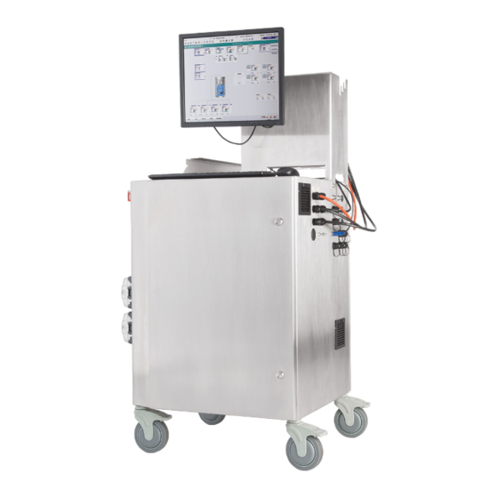
(COTS) control cabinet for use with a DeltaV ™ control platform from Emerson ™ Process Management. The system is ™ ™ controlled by Thermo Scientific TruBio Control Software: TruBioDV for DeltaV. Figure 1.1. G3Lite Bioreactor Controller. Thermo Scientific HyPerforma G3Lite Bioreactor Controller User’s Guide... -
Page 12: User Workstation
The monitor is supported by a mounting bracket that will support up to 20 kg (45 lb). The rear of the bracket also serves as a cable guide to hold cables and tubing. Thermo Scientific HyPerforma G3Lite Bioreactor Controller User’s Guide... -
Page 13: Pump Panel
(Figure 1.3). Power-indicator Main power Alarm buzzer Emergency Stop (E-Stop) Start/Reset Pump jogs Figure 1.3. Pump panel on the left side of the cabinet. Thermo Scientific HyPerforma G3Lite Bioreactor Controller User’s Guide... -
Page 14: Main Connector Panel
WARNING: The door allows access to the controller for service purposes, and should not be opened by the user unless instructed by Thermo Scientific personnel, as lethal voltages may be exposed. Thermo Scientific HyPerforma G3Lite Bioreactor Controller User’s Guide... - Page 15 (details shown in Figures 1.5–1.7) Figure 1.4. Main connector panel. Bag pressure Load cell 2 Load cell 1 Load cell 4 Load cell 3 pH connector DO connector Figure 1.5. Top eight conectors. Thermo Scientific HyPerforma G3Lite Bioreactor Controller User’s Guide...
- Page 16 G3Lite overview DO connectors pH connectors Spare Spares Alarm relay AI-1 AI-2 Figure 1.6. Ten middle connectors. AUX-1 AUX-2 Pinch valve TruLogic DO Pump tower Temp Digital agitator Figure 1.7. Last seven connectors. Thermo Scientific HyPerforma G3Lite Bioreactor Controller User’s Guide...
- Page 17 (8) pumps. Digital agitator—Optional two-position connection for signal and • power to a motor (described in section 2.9). See section 5.2 for information on connector pin configurations. Thermo Scientific HyPerforma G3Lite Bioreactor Controller User’s Guide...
-
Page 18: Second Connector Panel
Chapter 1 G3Lite overview 1.5 Second connector panel This panel is on the side opposite the pumps (Figure 1.8), and contains additional connectors. Figure 1.8. Second connector panel. Thermo Scientific HyPerforma G3Lite Bioreactor Controller User’s Guide... -
Page 19: Secondary Connector Faceplate (Left)
120 V AC or 240 V AC based on facility requirements. Ensure that adequate power is supplied to the Controller (15 A at 120 V AC or 6 A at 240 V AC). Thermo Scientific HyPerforma G3Lite Bioreactor Controller User’s Guide... - Page 20 E-Stop button located at the top of the vessel. For other vessels, it can also be used to trip other control panels if the local E-Stop button is pressed. Thermo Scientific HyPerforma G3Lite Bioreactor Controller User’s Guide...
-
Page 21: Secondary Connector Faceplate (Right)
USB mouse and USB keyboard—USB connectors for the mouse and keyboard, respectively. • HDMI—Connection to the HDMI monitor. • Plant LAN—An optional connection from the ProPlus computer to the plant Local Area Network. Thermo Scientific HyPerforma G3Lite Bioreactor Controller User’s Guide... - Page 22 Note: There are also filters for the exhaust fans on this panel. These must remain unobstructed to provide adequate ventilation to prevent the unit overheating. Thermo Scientific HyPerforma G3Lite Bioreactor Controller User’s Guide...
-
Page 23: Setup
If damage is found when the unit is unpacked, a claim should be filed with the shipper and your Thermo Scientific representative notified. It is recommended that the packing material be kept for possible future use. Any returns for service must be shipped in Thermo Scientific approved containers. 2.2 Setting up the controller The controller is free-standing, with lockable wheels. -
Page 24: Electrical Connections
Remove the plastic caps from all ports to be used. The TruFlow available comes with six inlets, one headspace (HS) outlet, as well as two sparger outlets (SPG-1, SPG-2), as shown in Figure 2.1 below. Thermo Scientific HyPerforma G3Lite Bioreactor Controller User’s Guide... -
Page 25: Connecting The Truflow
TruFlow. Refer to Figure 2.2 and Figure 2.3. Connect the RJ45 connection into the Ethernet port on the TruFlow Figure 2.2. TruFlow port on the controller. Figure 2.3. TruFlow communication ports. Thermo Scientific HyPerforma G3Lite Bioreactor Controller User’s Guide... - Page 26 6. Use a 9/16 in. or adjustable spanner wrench to tighten the nut by a full turn (Figure 2.6). Figure 2.6. Using a 9/16 in. wrench to Figure 2.5. Inserting the pneumatic tighten the nut. tubing into the TruFlow. Thermo Scientific HyPerforma G3Lite Bioreactor Controller User’s Guide...
-
Page 27: Connecting The Devicenet Cable To The Truflow
If you wish to switch the connections to the other side (only one side can be used) contact your Thermo Scientific representative for assistance. The TruFlow (Figure 2.7) is connected to the controller by a single ™... -
Page 28: Sensors And Auxiliaries
The 520-series pump (Figure 2.10) is larger and requires a flathead screwdriver to open. Figure 2.8. 114-series pump head. Figure 2.9. 313-series pump head. Figure 2.10. 520-series pump head. Thermo Scientific HyPerforma G3Lite Bioreactor Controller User’s Guide... -
Page 29: Installing Pump Tubing
See the appropriate TruBio Bioprocess Control Software Version 5.0 User’s Guide (DOC0088). • Ensure the tubing is not in danger of being kinked or occluded by other equipment. Thermo Scientific HyPerforma G3Lite Bioreactor Controller User’s Guide... -
Page 30: Pump Tubing Flow Rates
This table assumes tubing wall thickness of 1.6 mm for the series 114 and 313, and 2.4 mm for the series 520 pumps. Flow rates in this table assume continuous pumping. Flow rates of pulsed pumping will be lower. Thermo Scientific HyPerforma G3Lite Bioreactor Controller User’s Guide... -
Page 31: Computer Connection
If the system is a satellite, connected to one (1) G3Lite with ProPlus and TruLogic, then the previous situation will not be a problem. Figure 2.13. Architecture of two G3Lite units networked to the ProPlus workstation. Thermo Scientific HyPerforma G3Lite Bioreactor Controller User’s Guide... - Page 32 Operator Workstation. An optional wireless network can also be implemented using DeltaV Terminal Services, and a wireless tablet PC can be used to interface with the G3Lite. Consult your Thermo Scientific representative for further information on this option. Thermo Scientific...
-
Page 33: Connecting A Bioreactor Vessel
Connection for a D Agitator is on the lower end of the main connectors shown in section 1.4. This is a double connector, with one connector for the signal and the other for power to control a motor. Thermo Scientific HyPerforma G3Lite Bioreactor Controller User’s Guide... -
Page 34: Operation And Testing
TruFlow. The lights on the TruFlow gas manifold should come 6. Refer to DeltaV installation guidelines and the appropriate TruBio software guide for adding a new vessel. Operating instructions for TruBio software can be found in the appropriate user’s guide (DOC0088). Thermo Scientific HyPerforma G3Lite Bioreactor Controller User’s Guide... -
Page 35: Maintenance
Chapter 4 Maintenance Maintenance Each Thermo Scientific HyPerforma G3Lite Controller is fully tested before leaving the factory. The unit requires minimal maintenance; Thermo Scientific provides support, repair, maintenance, and refurbishment services for all G3-series systems sold. The doors of the controller are closed with two (2) quarter-turn latches. -
Page 36: Replacement Parts
Spare gas manifold (TruFlow) • Swagelock tubing ferrules and nuts (for TruFlow) • RTDs • pH and DO sensors • Sensor cables • Watson-Marlow series 114, 313, and/or 520 pump heads • Pump tubing Thermo Scientific HyPerforma G3Lite Bioreactor Controller User’s Guide... -
Page 37: Specifications And Parts Information
Heater blanket or analog Temperature Control Unit (TCU) Two (2) power and control connectors (usually Pall KleenPak Vent filter heaters KA3 or Meissner UltraCap 10-inch filters) External pumps Up to seven (7) pumps on a pump tower (optional) Thermo Scientific HyPerforma G3Lite Bioreactor Controller User’s Guide... - Page 38 K8 and VP D4, VP6, and VP8 TruFlow gas manifold DeviceNet Vent filter heater Binder 6-pin connector Vessel heater 240 VAC S.U.B. 50–2,000 L *Additional cable and connector information in section 5.2−Cables and connections Thermo Scientific HyPerforma G3Lite Bioreactor Controller User’s Guide...
- Page 39 Chapter 5 Specifications and parts information 78 cm (31 in.) 156 cm (61 in.) 60 cm (24 in.) Figure 5.1. Dimensions of the G3Lite. Thermo Scientific HyPerforma G3Lite Bioreactor Controller User’s Guide...
-
Page 40: Connector Pin Configurations
(white) *If using a 6-wire load cell, connect “Sense +” to “Excitation +” and “Sense –” to “Excitation –” **If using the optional Alarm Relay, pins 1 and 2 are dry contact Thermo Scientific HyPerforma G3Lite Bioreactor Controller User’s Guide... - Page 41 Outer shield Pin 5 +5V DC output Pin 6 Pin 7 Drain wire coupled to Pin 8 Pressure signal + pH signal cable Pinch valve connection Figure 5.4. G3Lite pinch valve connection configuration. Thermo Scientific HyPerforma G3Lite Bioreactor Controller User’s Guide...
-
Page 42: Cables And Connections
Control network (P1, P2, S1, S2) CAT5E with RJ45 connector 1P+N+E, 120 V/240 V, 15A, UPS circuit Power in recommended 1P+N+E, 120 V/240 V, 20.8A, non-UPS Power in—Heater (high wattage heater) circuit Thermo Scientific HyPerforma G3Lite Bioreactor Controller User’s Guide... -
Page 43: Fuses And Circuit Breakers
LED when power is supposed to be applied to the appropriate heater. If the heater temperature does not increase within three minutes, the fuse should be inspected and/or replaced. Use the following steps to replace the fuses. Thermo Scientific HyPerforma G3Lite Bioreactor Controller User’s Guide... - Page 44 If a circuit breaker has been tripped, the switch will be either in the “off” position or midway between the “on” and “off” positions. Push the switch fully into the “off” position, wait for a few seconds, and then to the “on” position. Thermo Scientific HyPerforma G3Lite Bioreactor Controller User’s Guide...
-
Page 45: General Ordering Information
General ordering information General ordering information 6.1 Ordering instructions Hardware components for the HyPerforma G3Lite Bioreactor Controller can be ordered directly from Thermo Fisher Scientific. These items include all components that have part numbers beginning with the following digits: •... -
Page 46: Technical Support
Chapter 6 General ordering information 6.3 Technical support Technical support for the HyPerforma G3Lite Bioreactor Controller is available in a variety of formats. Some or all of the following may be appropriate, depending on individual experience and circumstances. Technical service hotline and email... - Page 47 Find out more at thermofisher.com/sut For Research Use or Further Manufacturing. Not for diagnostic use or direct administration into humans or animals. © 2021 Thermo Fisher Scientific Inc. All rights reserved. All trademarks are the property of Thermo Fisher Scientific and its subsidiaries unless otherwise specified.
Need help?
Do you have a question about the HyPerforma G3Lite and is the answer not in the manual?
Questions and answers