Table of Contents
Advertisement
Quick Links
Advertisement
Table of Contents

Related Manuals for Agilent Technologies 8614 B Series


Summary of Contents for Agilent Technologies 8614 B Series
- Page 1 Agilent 8614xB Series Optical Spectrum Analyzer User’s Guide...
- Page 2 Agilent Technologies shall not be liable for any direct, indirect, special, incidental, Agilent Technologies makes no warranty of any kind or consequential damages whether based on con- with regard to this printed material, including, but tract, tort, or any other legal theory.
- Page 3 Safety Symbols. Typographical Conventions. CAUTION The following conventions are used in this book: Key type for keys or text located on the keyboard or The caution sign denotes a hazard. It calls attention to a procedure which, if not correctly performed or instrument.
- Page 4 General Safety Considerations General Safety Considerations This product has been designed and tested in accordance with the standards listed on the Man- ufacturer’s Declaration of Conformity, and has been supplied in a safe condition. The documenta- tion contains information and warnings that must be followed by the user to ensure safe operation and to maintain the product in a safe condition.
- Page 5 General Safety Considerations WARNING If this product is not used as specified, the protection provided by the equipment could be impaired. This product must be used in a normal condition (in which all means for protection are intact) only. WARNING No operator serviceable parts inside.
- Page 6 General Safety Considerations is only a standby switch and is not a LINE switch. Alternatively, an externally installed switch or circuit breaker (which is readily identifiable and is easily reached by the operator) may be used as a disconnecting device. CAUTION Always use the three-prong AC power cord supplied with this instrument.
-
Page 7: Table Of Contents
Contents 1 Getting Started Product Overview 1-2 Setting Up the Analyzer 1-8 Making a Measurement 1-12 The Menu Bar 1-15 The Softkey Panels 1-16 Laser Safety Information 1-27 Product Options and Accessories 1-28 2 Using the Instrument Setting Up Measurements 2-2 Calibrating Wavelength Measurements 2-13 Saving, Recalling, and Managing Files 2-18 Analyzing Measurement Data 2-26... - Page 8 Contents 7 Specifications and Regulatory Information Definition of Terms 7-3 Specifications 7-5 Regulatory Information 7-19 Declaration of Conformity 7-20 Contents-2...
-
Page 9: Getting Started
Product Overview 1-2 Setting Up the Analyzer 1-8 Making a Measurement 1-12 The Menu Bar 1-15 The Softkey Panels 1-16 Laser Safety Information 1-26 Product Options and Accessories 1-27 Getting Started... -
Page 10: Product Overview
Getting Started Product Overview Product Overview The 8614xB series of optical spectrum analyzers provide fast, accurate, and comprehensive mea- surement capabilities for spectral analysis. • Full-featured SCPI commands for programming instruments over LAN • Display-off feature for making faster measurements •... - Page 11 Getting Started Product Overview Amplifier Test Application This application simplifies the process of characterizing gain and noise figure of optical amplifiers such as EDFA’s, SOA’s and Raman amplifiers.
- Page 12 Getting Started Product Overview Agilent 8614xB Front and Rear Panels...
- Page 13 Getting Started Product Overview...
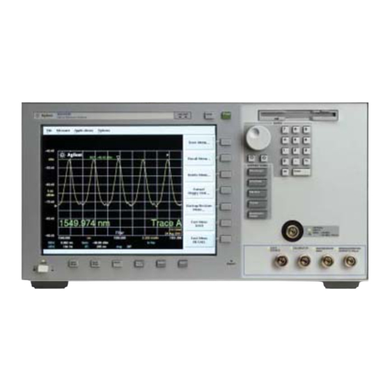
- Page 14 Getting Started Product Overview Optical Spectrum Analyzer Display Figure 1-1. Optical Spectrum Analyzer Display...
- Page 15 Getting Started Product Overview Figure 1-2. Display Annotations...
-
Page 16: Setting Up The Analyzer
Getting Started Setting Up the Analyzer Setting Up the Analyzer Step 1. Receive and Inspect the Shipment... - Page 17 6-21. If the shipment was damaged, contact the carrier, then contact the nearest Agilent Technologies Sales Office. Keep the shipping materi- als for the carrier’s inspection. The Agilent Technologies Sales Office will arrange for repair or replacement at Agilent Technologies’ option without waiting for claim settlement.
- Page 18 Parallel connector. Use a parallel Centronics printer cable, such as an HP C2950A (2 m) or HP C2951A (3 m). r The line cord provided is matched by Agilent Technologies to the country of origin on the order. Refer to “Accessories” on page 1-28.
- Page 19 Auto Align button. This will ensure optimal amplitude accuracy, and can correct for any mis-alignment caused by the instrument shipment. To learn more about this or any Agilent Technologies Optical Test and Measurement Products, visit our web site at http://www.agilent.com/comms/optical...
-
Page 20: Making A Measurement
Getting Started Making a Measurement Making a Measurement This procedure will introduce you to the Agilent 8614x series optical spectrum analyzer front panel controls. By following this procedure you will do the following: • Perform an auto alignment • Perform a peak search •... - Page 21 Getting Started Making a Measurement To perform an Auto Align For maximum amplitude accuracy, perform an automatic alignment whenever the optical spec- trum analyzer has been moved, subjected to large temperature changes, or following warm-up. “Auto Align” on page 3-9 for more information.
- Page 22 Getting Started Making a Measurement Using the delta marker The optical spectrum analyzer has four types of markers; normal markers, bandwidth markers, delta markers and noise markers. The marker currently being displayed is a normal marker. In the next step we will use it as a delta marker. 5 Press the front-panel Markers key.
-
Page 23: The Menu Bar
Getting Started The Menu Bar The Menu Bar The Menu bar includes the File, Measure, Application, and Options drop-down menus. Each menu selection includes a descriptive label. (Action) Indicates the selection will perform an action such as making a measurement or printing the display. (Panel) Indicates the selection will open a softkey panel. -
Page 24: The Softkey Panels
Getting Started The Softkey Panels The Softkey Panels You can access the softkey panels using either the front-panel keys or the menu bar. This section includes brief descriptions of the following menus. See Chapter 3, “Function Reference” for addi- tional information on each of the OSA functions. The Amplitude Menus 1-17 The Applications Menus 1-17 The Bandwidth/Sweep Menus 1-19... - Page 25 Getting Started The Softkey Panels The Amplitude Menus You can access the Amplitude softkeys using the front-panel Amplitude key or the Measure menu Amplitude selection on the menu bar. The Applications Menus You can access the Applications (Appl’s) softkeys by using the front-panel Appl’s key or the Applications menu Launch an Installed Application section on the menu bar.
- Page 26 Getting Started The Softkey Panels 1-18...
- Page 27 Getting Started The Softkey Panels The Bandwidth/Sweep Menus You can access the Bandwidth/Sweep softkeys by using the front-panel Bandwidth/Sweep key or the Measure menu Bandwidth/Sweep selection on the menu bar. 1-19...
- Page 28 Getting Started The Softkey Panels The Markers Menus You can access the Markers softkeys by using the front-panel Markers key or the Measure menu Markers selection on the menu bar. 1-20...
- Page 29 Getting Started The Softkey Panels The Save/Recall Menus You can access the Save/Recall softkeys and setup panels by using the drop-down File menu Save/Recall selection or the front-panel Save/Recall key. Use these functions to save, recall and print the measurement results. 1-21...
- Page 30 Getting Started The Softkey Panels The Systems Menus You can access the System softkeys by using the front-panel System key or the Options menu System selection on the menu bar. 1-22...
- Page 31 Getting Started The Softkey Panels The Systems Menus, continued..1-23...
- Page 32 Getting Started The Softkey Panels The Traces Menus You can access the Traces softkeys by using the front-panel Traces key or the Measure menu Traces selection on the menu bar. 1-24...
- Page 33 Getting Started The Softkey Panels The Wavelength Menus You can access the Wavelength softkeys by using the front-panel Wavelength key or the Mea- sure menu Wavelength selection on the menu bar. 1-25...
-
Page 34: Laser Safety Information
Getting Started Laser Safety Information Laser Safety Information • Laser Safety Information The light sources specified by this user guide are classified according to IEC 60825-1 (2001). The light sources comply with 21 CFR 1040.10 except for deviations pursu- ant to Laser Notice No. 50, dated 2001-July-26 Laser type Edge em itting LED (EELED) W avelength... -
Page 35: Product Options And Accessories
Getting Started Product Options and Accessories Product Options and Accessories Options Agilent 86142B, 86146B Agilent 86143B, 86145B Benchtop Portable Instrument System Options Current Source Opt. 001 ---- White Light Source Opt. 002 ---- Built-in 1310 & 1550 nm EELED Source Opt. - Page 36 Getting Started Product Options and Accessories Table 1-3. Accessories Option Description Product Number Item Quantity Connector Accessories FC/PC Connector Adapter 08154-61702 FC/PC Dust Cap 1401-0291 Angled to Flat, FC/PC Adapter 1250-3175 DIN Optical Connector Adapter 08154-61703 DIN Dust Cap 1401-0291 ST Optical Connector Adapter 08154-61704 ST Dust Cap...
- Page 37 Getting Started Product Options and Accessories Table 1-4. Available Fiber Sizes Model Optical Option 006 Photo- Mono Output Option 002 Option 004 Option 005 Number Input (Calibrator) diode (White Light (1310/1550 (1550 EELED) Input Source) EELED) µ µ 86143B µ µ...
- Page 38 Getting Started Product Options and Accessories Table 1-5. Additional Parts and Accessories Agilent Benchtop OSA Agilent Portable OSA 86142B, 86146B 86143B, 86145B Printer Paper (5 rolls/box) 9270-1370 9270-1370 Additional Connector Interfaces See Agilent 81000 series See Agilent 81000 series External 10 dB Attenuator (FC/PC) Opt.
- Page 39 Getting Started Product Options and Accessories Front Panel Fiber-Optic Adapters Front Panel Description Agilent Part Number Fiber-Optic Adapter 08154-61702 FC/PC 08154-61708 08154-61703 08154-61704 a. The FC/PC is the default front-panel optical connector. 1-31...
- Page 40 Getting Started Product Options and Accessories 1-32...
-
Page 41: Using The Instrument
Setting Up Measurements 2-2 Calibrating Wavelength Measurements 2-13 Saving, Recalling, and Managing Files 2-18 Analyzing Measurement Data 2-26 Analyzer Operating Modes 2-29 Using the Instrument... -
Page 42: Setting Up Measurements
Using the Instrument Setting Up Measurements Setting Up Measurements This section contains the following information that will help you set up a wavelength measure- ment: • Adjusting Setup Conditions • Operating the Internal White Light Source • Averaging Traces • Setting Video Bandwidth •... - Page 43 Using the Instrument Setting Up Measurements Adjusting Setup Conditions Setup panels allow you to adjust setup conditions which are not frequently changed. Refer to “Preset” on page 3-59. Using the softkeys Arrows allow you to navigate from field to field in the dialog box. The highlighted parameter can be changed.
- Page 44 Using the Instrument Setting Up Measurements Operating the Internal White Light Source For Option 002 only Option 002 provides a built-in white light source which is a stable, broadband light source for swept-wavelength stimulus response testing from 900 nm to 1700 nm. The light source is ideal to perform stimulus-response measurements, and measure photodetector responsivity.
- Page 45 Using the Instrument Setting Up Measurements Averaging Traces Trace averaging improves your measurement repeatability by smoothing out noise. For measure- ments involving slow polarization scrambling, using video filtering to improve repeatability will require a very narrow video bandwidth (less than 10 Hz). This would result in a long measure- ment time, where trace averaging would be faster.
- Page 46 Using the Instrument Setting Up Measurements Setting Video Bandwidth Video bandwidth filtering occurs after the detection of the light. In the auto coupled mode, the video bandwidth has an extremely wide range. This allows the instrument to avoid unnecessary filtering that would reduce the sweep speed more than required. Refer to “Video BW”...
- Page 47 Using the Instrument Setting Up Measurements 1 From the front panel, press Bandwidth/Sweep > Video BW. 2 Toggle to select the video bandwidth automatically or manually. 3 Use the knob, step keys, or numeric entry pad to enter the desired value. N o t e For measurements with slow polarization scrambling, use trace averaging to improve measurement repeatability.
- Page 48 Using the Instrument Setting Up Measurements Setting the Sensitivity Setting sensitivity requests the lowest amplitude signal that can be measured relative to the high- est amplitude signal displayed. It is defined as the signal that is six times the RMS noise. The min- imum setting is –100 dB.
- Page 49 Using the Instrument Setting Up Measurements Triggering a Measurement Triggering a measurement synchronizes the start of the sweep to an internally generated trigger signal. Internal triggering ensures continuously triggered sweeps with the shortest delay between sweeps. Refer to “Trigger Mode, Internal” on page 3-88.
- Page 50 Using the Instrument Setting Up Measurements The display will have at least one data sample marked as valid (high level) per trace point. Or else you can use the Max Hold function to complete a trace over several sweeps. Multiple sweeps fill the gaps because the high and low levels of the gating signal occur independent of the grating position.
- Page 51 Using the Instrument Setting Up Measurements Moving the Active Function Area The active function area on the display can be moved to eight different locations. This allows you to place the active area in a location that will not interfere with the trace information. Refer to “Active Function Area Assist”...
- Page 52 Using the Instrument Setting Up Measurements Indicating an Update is Needed This feature alerts you to take a sweep after changing any sweep related parameters when the analyzer is not in sweep mode. For example, if you change the resolution bandwidth, the new resolution bandwidth is displayed on the bottom of the screen, but the trace data displayed on the screen used the previous resolution bandwidth value.
-
Page 53: Calibrating Wavelength Measurements
Using the Instrument Calibrating Wavelength Measurements Calibrating Wavelength Measurements Environmental variations such as air pressure, temperature, and humidity can affect the index of refraction of air in the monochromator of the optical spectrum analyzer (OSA). This section dis- cusses calibration methods that you can use to improve the wavelength accuracy in the Agilent 8614xB OSA’s. - Page 54 Using the Instrument Calibrating Wavelength Measurements Internal Wavelength Calibration The optional internal calibrator (1513 to 1540 nm) provides a convenient method for increasing wavelength accuracy when used with an internal Enhanced Wavelength Calibration (EWC) pro- cess. The wavelength accuracy of the OSA will be ±0.2 nm over the full wavelength range of the instrument, with ±10 pm over 1480 to 1570 nm and ±25 pm accuracy over 1570 to 1620 nm.
- Page 55 Using the Instrument Calibrating Wavelength Measurements External Single Wavelength Calibration Using an external single-point calibration source allows the calibration to be done at a specific wavelength. This single wavelength user calibration can be repeated as often as necessary to correct for environmental variations and existing multipoint wavelength offsets will be adjusted accordingly.
- Page 56 Using the Instrument Calibrating Wavelength Measurements External Multipoint Wavelength Calibration An external multipoint wavelength calibration can be performed over any specified wavelength range, up to and including the full wavelength range of the OSA (600 nm to 1700 nm). Narrow measurement spans can be chosen to provide greater accuracy over a selected range.
- Page 57 Using the Instrument Calibrating Wavelength Measurements To insure this offset process has provided sufficient accuracy, the wavelength readings of the multi-wavelength meter and the OSA should be compared to verify the wavelength accuracy and determine if a full multipoint wavelength recalibration is necessary. 2-17...
-
Page 58: Saving, Recalling, And Managing Files
Using the Instrument Saving, Recalling, and Managing Files Saving, Recalling, and Managing Files The functions and methods available for saving, recalling, and managing files that contain mea- surement setups and results are as follows: • Adding a Title to the Display •... - Page 59 Using the Instrument Saving, Recalling, and Managing Files Backing Up or Restoring the Internal Memory 1 Press the front-panel Save/Recall key. 2 Press the Backup/Restore Menu..softkey. N o t e The auto span value will not be saved with the measurement. Refer to “Backup Internal Memory”...
- Page 60 Using the Instrument Saving, Recalling, and Managing Files N o t e The auto span value will not be saved with the measurement. Saving Measurement and Trace Data 1 Press the front-panel Save/Recall key. 2 Press the Save Menu..softkey. 3 The Save Setup panel opens.
- Page 61 Using the Instrument Saving, Recalling, and Managing Files Save Graphics Allows you to save graphic data in one of two formats. These selections are valid only when sav- ing to the floppy drive. CGM (Computer Graphics Metafile format) is a vector graphics format that describes pictures and graphical elements in geometric terms.
- Page 62 Using the Instrument Saving, Recalling, and Managing Files of the filename. • When the desired letter or function is selected, press the Select softkey. • Select the BackSpace function to delete individual letters. • Select the Clear Line function to delete the entire filename. •...
- Page 63 Using the Instrument Saving, Recalling, and Managing Files Recalling Measurement and Trace Data You can recall measurement and trace data using the following methods: • Fast Measurement Recall Mode • Recall Setup Panel Mode Refer to “Recall (Recall Setup Panel)” on page 3-61.
- Page 64 Using the Instrument Saving, Recalling, and Managing Files Recall From Selects whether to recall from a floppy disk or from internal memory. 4 When you are satisfied with your selections, press the Choose File to Recall softkey. The Catalog setup panel opens. The Catalog setup panel 5 Use the arrow keys or Prev File, Next File softkeys to highlight the desired file.
- Page 65 Using the Instrument Saving, Recalling, and Managing Files File Sharing and Printing over a Network This function uses the LAN to print to network printers and store, recall or delete data on remote hard drives. The data can then to be accessed and shared among the users and printed on desig- nated printers.
-
Page 66: Analyzing Measurement Data
Using the Instrument Analyzing Measurement Data Analyzing Measurement Data This section provides advice and information on the following analyzer functions that allow you to analyze the measured amplitude wavelength data. • Tips for Using Traces and Markers • Measuring the Delta between Traces •... - Page 67 Using the Instrument Analyzing Measurement Data The color of the annotation denotes different characteristics of the markers: • White annotation denotes the status of the currently active marker. • Green annotation denotes the status of all currently used markers. • Red annotation denotes that some type of an error occurred with the marker measurement. Moving the Active Marker from One Trace to Another The following procedure shows you how to move the active marker (marker 1) from Trace A to Trace B.
- Page 68 Using the Instrument Analyzing Measurement Data Using Trace Math to Measure Wavelength Drift 1 From the front panel, press Traces > Active Trace > TrA. 2 Press Single Sweep, Bandwidth Sweep, Single Sweep to update Trace A then press Traces, Update A off.
-
Page 69: Analyzer Operating Modes
Using the Instrument Analyzer Operating Modes Analyzer Operating Modes This section discusses the following analyzer modes that you can use in specific measurement applications. • Filter Mode (For Agilent 86146B only) • Time Resolved Chirp Filter Mode For Agilent 86146B only The Agilent 86146B filter mode allows a single channel from a dense wavelength division multi- plex (DWDM) signal to be isolated and routed to another measurement instrument. - Page 70 Using the Instrument Analyzer Operating Modes adjusting the marker’s position, then connecting the monochromator output to another instru- ment. If the input spectrum changes, reconnect the monochromator output, then press the Take Sweep softkey to capture a new sweep. The single mode filter can be used in conjunction with the Agilent 86130A bitalyzer error perfor- mance analyzer and/or the Agilent 86100A infinium digital communication analyzer.
- Page 71 Using the Instrument Analyzer Operating Modes Table 2-6. Agilent 86146B unique operation 86146B Unique Operation (External 9 µm Fiber Connection) Filter mode initialization: • No default settings Markers used: • Filter marker is the normal noise marker • OSNR marker is the center marker •...
- Page 72 Using the Instrument Analyzer Operating Modes Switch Path Auto Align Now switches to the 9 µm filter mode path and performs an Auto Align. This aligns the output of the monochromator with the photodetector input for improved ampli- tude accuracy. The automatic alignment procedure should be performed whenever the instru- ment has been: •...
- Page 73 Using the Instrument Analyzer Operating Modes 9 If the input light changes, or if you change the span of the optical spectrum analyzer, reconnect the monochromator output to the photodetector input, and press Take Sweep to update the displayed trace with valid waveform data. 10 Press Exit Filter Mode to return to normal optical spectrum analyzer operation.
- Page 74 Using the Instrument Analyzer Operating Modes Time Resolved Chirp For Agilent 86146B option DPC only The Agilent 86146B, with the filter mode capability, will measure side mode suppression ratio (SMSR), wavelength, and power. With the addition of an Agilent 86100 Infinium Digital Commu- nications Analyzer (DCA), dedicated software (86146B Option TRL), and a personal computer, time resolved chirp (TRC) of a modulated laser can be calculated.
-
Page 75: Function Reference
Function Reference... - Page 76 Function Reference Function Reference Function Reference This chapter is an alphabetical reference of front panel keys, softkeys, and setup panel parame- ters. It is designed for quick information access. For example, during an operation you may find a key whose function is unfamiliar to you. Note the key name and look the key up in this chapter. Active Function Area Assist Sets the active function area to the first or top softkey function.
- Page 77 Function Reference Active Marker Active Marker Accesses the menu that allows you to select an active marker. Selecting a marker always places that marker on the center wavelength of the active trace. Up to four markers can be simulta- neously displayed. If multiple markers are displayed, the active marker appears as a white dia- mond and the other markers appear as green diamonds.
- Page 78 Function Reference Adv Service Functions Adv Service Functions Accesses the following functions: • Grating Order • More Adv Service Menu • Wavelength Limit • Zero Now Key Path System > More System Functions > Service Menu > Adv Service Functions Advanced Line Mkr Functions Accesses the following functions: •...
- Page 79 Function Reference All Off All Off Turns all the active markers off. N o t e If filter mode is on, this function is not available. Key Path Markers > Active Marker > All Off Remote Commands CALCulate[1|2|3|4|5|6]:MARKer[1|2|3|4]:AOFF Amplitude Accesses the menu of keys that allow you to control the instrument’s sensitivity and amplitude scales.
- Page 80 Function Reference Amplitude Setup The Amplitude Setup panel Setup Panel Selections Reference Level Position The value selected for the Reference Level Position determines the position of the reference level on the graticule. Setting this value to zero divisions places the reference level on the very bottom of the grid.
- Page 81 Function Reference Amplitude Setup Auto Ranging The Auto Range function allows the OSA to automatically change the gain of the transimpedance amplifier during a sweep. This allows measurements to be made at the largest dynamic range and at the fastest sweep speed. Pressing the front-panel Preset key turns Auto Ranging N o t e It is recommended that Auto Ranging always be turned on.
- Page 82 Function Reference Amplitude Units (Amplitude Setup Panel) Amplitude Correction Sel Allows you to select a correction set to be applied to the measurement results. Only one set can be selected at a time. Refer to “Amplitude Correction Remote Commands” on page 1-24 of the “Agilent 8614xB Series Optical Spectrum Analyzer Programming Guide”...
- Page 83 Function Reference Auto Align Remote Commands UNIT:POWer Auto Align Pressing the auto align button on the front panel of the instrument performs an automatic align- ment of the instrument using the largest signal found in a full span sweep. This aligns the output of the monochromator with the photodetector for improved amplitude accuracy.
- Page 84 Function Reference Auto Align & Add to Trajectory Auto Align & Add to Trajectory Allows alignment at several wavelengths, ensuring amplitude accuracy of your measurements. Before initiating the alignment, connect a broadband light source to the front-panel input con- nector. (You may add and/or update the existing points in the trajectory table.) Press Auto Align Preset to clear the table.
- Page 85 Function Reference Auto Meas The auto measure function uses trace A to perform the measurement. Since the auto measure function can alter the instrument state, we recommend that this operation be performed before a measurement sequence is started. Auto Measure Setup panel allows you to modify the auto measure span and the vertical scale, tune to the wavelength indicated by the marker, and optimize the sensitivity.
- Page 86 Function Reference Auto Ranging (Amplitude Setup Panel) Auto Ranging (Amplitude Setup Panel) When on, the auto ranging allows the OSA to achieve the desired sensitivity by taking several sweeps and switching between gain stages. The final trace data is a blended composite of each trace taken in the different gain stages.
- Page 87 Function Reference Averaging Averaging When averaging is on, you can select the number of measurement sweeps to be averaged, using the 10, 20, 50, 100 softkeys. You can also enter averaging values other than those displayed by using the numeric keypad or the knob. When the number of sweeps taken is less than the count, the following formula is used to calcu- late the data: AVG = sum of current sweeps/ number of averages selected...
- Page 88 Function Reference Backup/Restore Menu Backup/Restore Menu Accesses the instrument utilities used to backup or restore internal memory. Key Path Save/Recall > Backup/Restore Menu 3-14...
- Page 89 Function Reference Bandwidth Marker Interpolation (Marker Setup Panel) Bandwidth Marker Interpolation (Marker Setup Panel) Turns the bandwidth marker interpolation on or off. When on, the bandwidth markers will be placed at the exact number of dB (NDB) from the normal marker, if within the trace range. The position of the marker will be linearly interpolated between the two nearest trace data points.
- Page 90 Function Reference Calibration Key Path Markers > Marker Setup > BW Marker Units Related Functions Marker BW Remote Commands CALCulate[1|2|3|4|5|6]:MARKer[1|2|3|4]:FUNCtion:BANDwidth:READout Calibration Accesses the Power Cal Setup and Wavelength Calibration Setup softkeys. The Power Calibra- tion Setup panel will show the date of the last factory performed power calibration and the date of the last successful user-performed power calibration.
- Page 91 Function Reference Center Wavelength (WL) The instrument automatically sets the start wavelength at 1490 nm, stop wavelength at 1590 nm, span, and reference level, and then performs a fully automatic, internal auto align. The input signal is aligned at equally spaced alignments (minimum 50 nm spacing between points) for the internal, multi-mode fiber or (minimum 5 nm spacing between points) for the external, single- mode fiber (Agilent 86146B only).
- Page 92 Function Reference Center Wavelength Step Size (Wavelength Setup Panel) Center Wavelength Step Size (Wavelength Setup Panel) Specifies the center wavelength step size. This is used for incrementing center wavelength using the ¦ and Ø keys. Key Path Wavelength > Wavelength Setup > Center Wavelength Step Size Remote Commands SENSe:WAVelength:CENTer:STEP:INCRement Configure Network...
- Page 93 Function Reference Date/Time (Display Setup Panel) Remote Commands SOURce:CURRent:PULSe:STATe ON|OFF Date/Time (Display Setup Panel) Turns the date and time on the display on or off. When on, the date and time will appear on the display’s lower, right corner of the display and on printouts. Key Path System >...
- Page 94 Function Reference Delete From (Delete Setup Panel) Delete From (Delete Setup Panel) Selects whether to delete a file from a floppy disk, internal memory, or a networked file share. Key Path Save/Recall > Delete Menu > Delete File From Remote Commands MMEMory:DELete Delete Menu Accesses the Delete Setup panel that allows you to delete files from a floppy disk, internal mem-...
- Page 95 Function Reference Delta Marker Units (Marker Setup Panel) Delta Marker Units (Marker Setup Panel) Sets the delta marker X-axis readout for frequency or wavelength when the instrument is in a non-zero span. The available selections are nm, µm, Ang, GHz, and THz. The default units are nm (nanometers).
- Page 96 Function Reference Display Setup The Display Setup panel Setup panel selections Agilent Logo When this function is , the Agilent logo is shown on the display and printouts. Date/Time Turns the date and time on the display. Title Turns the title on the display.
- Page 97 Function Reference Exchange Menu Exchange Menu Accesses the trace exchange selections which include: • A Exchange B • B Exchange C • C Exchange A • D Exchange A • E Exchange A • F Exchange A Exchanges the X- and Y-axis data of the two traces. The trace pairs that can be exchanged are Trace A with any trace, and Trace B with Trace C.
- Page 98 Function Reference Fast Meas Save Key Path Save/Recall > Fast Meas Recall Related Functions Recall, Fast Meas Save Fast Meas Save Accesses the fast measure save function to save the current measurement state to internal mem- ory as FASTSAVE.dat. Allows a quick save of the current state, which can then be recovered by the Fast Meas Recall function.
- Page 99 Function Reference File Shares File Shares Uses the LAN (local area network) to store, recall, and delete files on remote hard drives. The data can then be accessed and shared among the users. To access the file and printer share softkeys, you must first configure the network refer to “Con- necting to the OSA over the Network”...
- Page 100 Function Reference Filter Mode N o t e During filter mode, the noise marker, delta marker, and OSNR marker are disabled. Key Path Appl’s > Measurement Modes > Filter Mode > Switch Path Auto Align Now or Switch Path No Auto Align > Filter Marker Tune Remote Commands CALCulate[1|2|3|4|5|6]:MARKer:SRLevel INPut:FILTer:SCENt...
- Page 101 Function Reference Firmware Upgrade Firmware Upgrade The instrument will restart into a utility to upgrade the instrument firmware. For upgrade instruc- tions, or to order a firmware upgrade kit, visit or web site at http://www.agilent.com/comms/ osaupgrade Key Path System > More System Functions > Service Menu > Firmware Upgrade Format Floppy Disk Formats a 3.5, 1.44 MB floppy disk.
- Page 102 Function Reference GPIB Address Key Path Save/Recall > Format Floppy Disk GPIB Address Accesses the GPIB address information. To change the address, use the numerical entry keys, step keys, or knob to enter the new GPIB address information. If changes are made, press the Select softkey.
- Page 103 Function Reference Hold A...F None Min Max (trace) Hold A...F None Min Max (trace) Hold Max compares the current amplitude value of each point on the active trace in the current sweep to the corresponding point detected during the previous sweep, then displays the maxi- mum value.
- Page 104 Function Reference Line Marker Menu Key Path System > Options > Light Source Related Functions Current Source Setup Remote Commands SOURce:CATalog SOURce:STATe Line Marker Menu Accesses the following line marker functions: • Advanced Line Mkr Functions • Line Markers Off •...
- Page 105 Function Reference Lin Math C=A+B Key Path Traces > Trace Math OFF > Default Math Trace C > Lin Math C=A–B Remote Commands CALCulate3:MATH:EXPRession(TRA–TRB) Lin Math C=A+B Adds Trace A and Trace B point by point, then stores the results in Trace C in linear units. The results of this function often require a reference level adjustment.
- Page 106 Function Reference Log Math C=A+B Related Functions Log Math C=A+B, Log Math F=C–D Remote Commands CALCulate3:MATH:EXPRession(TRA/TRB) Log Math C=A+B Adds Trace A and Trace B point by point, then stores the results in Trace C in logarithmic units. The results of this function often require a reference level adjustment. Trace A is placed in View On mode.
- Page 107 Function Reference Marker BW Marker BW Measures the passband of the signal. To enter the bandwidth amplitude of the bandwidth mark- ers, make a selection from the softkeys (–3 dB, –6 dB, –10 dB, and –20 dB) or use the knob, step keys, or numeric keys. Marker band- width information is displayed at the top of the graticule.
- Page 108 Function Reference Marker Search Menu Marker Search Menu Accesses the following marker peak and pit search functions: • peak or pit search mode • peak or pit search • next peak down, left or right • next pit up, left or right •...
- Page 109 Function Reference Marker Setup Marker Setup Accesses a menu that allows you to make changes to default marker settings. From the setup panel you can make changes to: • Bandwidth/Marker Interpolation On|Off • BW Marker Units • Delta Marker Units •...
- Page 110 Function Reference Marker Setup Setup Panel Selections Normal Marker Units Sets the X-axis immediately displayed marker information for frequency or wavelength when the instrument is in a non-zero span. This setting controls only the normal marker X-axis and the delta reference immediately displayed information.
- Page 111 Function Reference Marker Setup Peak Excursion Determines (in dB) which side modes are included in the measurements. To be accepted, each trace peak must rise, and then fall, by at least the peak excursion value about a given spectral component. The default value is 3 dB. Setting the value too high may result in not identifying a side mode.
- Page 112 Function Reference Marker Setup often causes pit searches to identify noise spikes. To avoid this misidentification, use video aver- aging or video filtering to reduce the noise floor variance to a value less than the pit excursion definition. Use Marker Search Threshold This limits the marker search function to data points above the selected threshold level.
- Page 113 Function Reference Marker to Center Marker to Center Changes the center wavelength to the wavelength of the active marker. Key Path Markers > Marker to Center Remote Commands CALCulate[1|2|3|4|5|6]:MARKer[1|2|3|4]:SCENter Marker to Ref Level Changes the reference level to the amplitude of the active marker. Key Path Markers >...
- Page 114 Function Reference More Marker Functions Measurement Mode For Agilent 86146B only Accesses filter mode and power meter mode. Key Path Appl’s > Measurement Modes Related Functions Filter mode, Power Meter mode Remote Commands INSTrument:NSELect INSTrument:SELect More Marker Functions Accesses the following marker search functions: •...
- Page 115 Function Reference Move Active Area Move Active Area Moves the active function area to one of eight on-screen locations. To change the active function area location, press the Move Active Area softkey until you are satisfied with the position. Key Path System >...
- Page 116 Function Reference New GPIB Address (Remote Setup Panel) New GPIB Address (Remote Setup Panel) Allows you to enter a new GPIB address. To change the address, use the numeric entry keys, step keys, or knob. Press the Defaults softkey to reset the address to the factory preset default, 23. Key Path System >...
- Page 117 Function Reference Next Peak Right Next Peak Right Places the marker on the next peak located at a higher X-axis value (usually wavelength) than the current marker position. This peak must meet the peak excursion and threshold criteria. If the specified marker is off, it will be turned on and placed at the center wavelength or frequency.
- Page 118 Function Reference Next Pit Up Next Pit Up Places the active marker on the next lowest pit from the current marker amplitude. This pit must meet the pit excursion and threshold criteria. If the specified marker is off, it will be turned on and placed at the center wavelength.
- Page 119 Function Reference Normal Marker Units (Marker Setup Panel) Related Functions Active Marker, Delta Marker Remote Commands CALCulate[1|2|3|4|5|6]:MARKer[1|2|3|4]:INTerpolation Normal Marker Units (Marker Setup Panel) Sets the marker X-axis readout for frequency or wavelength when the instrument is in a non-zero span. The X-axis default units is nm (nanometers). This setting controls only the normal marker X- axis readout and the delta reference readout.
- Page 120 Function Reference OSNR Marker N o t e For Agilent 86146B only, if filter mode is enabled, the noise marker, marker BW, delta marker, and OSNR marker are disabled. = noise marker symbols N = interpolated noise = interpolated noise amplitude P = peak = peak amplitude = center wavelength...
- Page 121 Function Reference OSNR Marker Error Messages OSNR error messages are displayed in red letters and are described below with suggestions to correct the error. Noise Not Found can be displayed for two different conditions. The first condition occurs when Pit mode is selected, and the left or right marker is unable to find a pit using the Pit Excursion (selected in the Marker Setup panel).
- Page 122 Function Reference OSNR Marker Center Not Found error message Key Path Markers > More Marker Functions > OSNR Marker Remote Commands CALCulate[1|2|3|4|5|6]:MARKer[1|2|3|4]:FUNCtion:OSNR[:STATe} OFF|ON|0|1 3-48...
- Page 123 Function Reference Options Options Accesses the Current Source Setup and Light Source Output Setup softkeys. Current Source Setup panel allows you to set the current limit, enable pulse mode and synchro- nize the ADC sync output. See “Current Source Setup” on page 3-18 Light Source panel turns the desired light source on or off.
- Page 124 Function Reference OSA State OSA State Displays the state information. The state information includes: • center wavelength • model # • options • serial # • software revision • span • start wavelength • stop wavelength • wavelength offset • wavelength step You can print this information using the internal or external printer.
- Page 125 Function Reference Peak to Center Peak to Center Finds the highest amplitude trace point and sets the center wavelength to that wavelength. Key Path Wavelength > Peak to Center Remote Commands CALCulate[1|2|3|4|5|6]:MARKer[1|2|3|4]:MAXimum CALCulate[1|2|3|4|5|6]:MARKer[1|2|3|4]:SCENter SENSe:WAVelength:CENTer Peak Excursion (Marker Setup Panel) Sets the peak excursion value for the marker search functions. Peak excursion criteria For marker search functions, a signal peak is defined as a rise and fall in the displayed response by at least the peak excursion value.
- Page 126 Function Reference Peak Search Peak Search Places a marker on the highest amplitude trace point. If no marker is on, Marker #1 will be used for the peak search. Next Peak Down Places the marker on the next highest peak from the current marker amplitude. This next highest peak must meet the peak excursion and threshold criteria.
- Page 127 Function Reference Peak Search at End of Each Sweep (Marker Setup Panel) Key Path Markers > Peak Search Markers > More Marker Functions > Marker Search Menu > Search Mode Peak > Peak Search Remote Commands CALCulate[1|2|3|4|5|6]:MARKer[1|2|3|4]:MAXimum Peak Search at End of Each Sweep (Marker Setup Panel) Finds the peak value of the trace and moves the active marker to the peak at the end of each sweep.
- Page 128 Function Reference Pit Excursion (Marker Setup Panel) Pit Excursion (Marker Setup Panel) Sets the pit excursion value for the marker search routines. Pit excursion criteria The pit excursion value is used to determine whether or not a local minimum in the trace is to be considered a pit.
- Page 129 Function Reference Power Calibration Setup Power Calibration Setup Accesses the setup panel to set the calibration power and calibration wavelength. Set Calibration Power is the exact amplitude of the calibration source that will be used for the next power calibration. The power entered must be within +10 dB and –3 dB of the amplitude measured using the factory calibration.
- Page 130 Function Reference Power Calibration Setup Power Meter Mode For 86146B only Power meter operation is an operation mode available on the 86146B instruments. Power meter mode displays the broadband power of the input light over time. The input light is directly con- nected to the instrument’s photodetector.
- Page 131 Function Reference Power Calibration Setup Related Functions Power display Power meter mode Remote Commands CALibration:ZERO[:AUTO] ONCE Power Meter Units For Agilent 86146B only Displays the power meter units automatically in watts or in dBm. Key Path Appl’s > Measurement Modes > Power Meter Mode > Pwr Mtr Units Remote Commands CALibration:POWer:VALue <param>...
- Page 132 Function Reference Power On State IP/Last Power On State IP/Last Selects the state, IP or Last, of the instrument when it is turned on. The default state is IP. If IP is selected, the instrument will turn on in a known, preset state. With the settings as they would be after pressing the front-panel Preset key.
- Page 133 Function Reference Preset Preset Resets the instrument to a known preset state. Selecting preset aborts any current operations and clears the GPIB output queue. Preset leaves some settings in place, for example, the title on the display. Table 3-7. Default values Function Preset Value Function...
- Page 134 Function Reference Print Function Preset Value Function Preset Value Marker 1–4 bandwidth amplitude –3 dB Marker 1–4 delta Marker 1–4 noise Marker 1–4 delta marker units Current trace Trace integration Trace integration limit Trace mean Trace mean limit Trace average count ASCII TRA visibility Trace data format...
- Page 135 Function Reference Recall (Recall Setup Panel) Key Path System > Printer Setup Remote Commands HCOPy:DESTination Printer Shares Uses the LAN (local area network) to print data to network printers. The data can be printed on designated, PCL3 format or newer printers. To access the printer share softkeys, you must first configure the network refer to “Connecting to the OSA over the Network”...
- Page 136 Function Reference Recall From (Recall Setup Panel) Remote Commands (Measurement) *RCL (Trace Only):MMEMory:LOAD:TRACe (File Share):MMEMory:CATalog?FSHare1FSHare2|FSHare3|FSHare4 Recall From (Recall Setup Panel) Selects whether the data is recalled from a floppy disk, from internal memory, or from network file share. See “Recalling Measurement and Trace Data” on page 2-23 Key Path Save/Recall >...
- Page 137 Function Reference Recall Menu Recall Menu Accesses the Recall Setup panel for the following settings: • Recall (all measurement data or trace data only) • Recall From (recall from a floppy disk or from the internal drive • Network File Share 1|2|3|4 •...
- Page 138 Function Reference Reference Level Position (Amplitude Setup Panel) Reference Level Position (Amplitude Setup Panel) Determines the position of the reference level on the graticule. Setting this value to zero divisions places the reference level on the very bottom of the grid. Setting the reference level to 10 divi- sions places the reference level at the top of the grid.
- Page 139 Function Reference Remote Printer Share Panel Remote Printer Share Panel Uses the LAN (local area network) to print to designated, network printers. See “Recalling Mea- surement and Trace Data” on page 2-23 N o t e To access the file and printer share softkeys, you must first configure the network and enter the user share identity/user profile information for remote shares.
- Page 140 Function Reference Res BW Res BW Sets the resolution bandwidth value to be used. This determines the instrument’s ability to display two closely spaced signals as two distinct responses. The resolution bandwidth can be set to one of the following values: •...
- Page 141 Function Reference Reset Min/Max Hold Reset Min/Max Hold Resets trace hold data and returns to the Traces function keys where you can select an active trace, trace input, update, view, and hold functions. Key Path Traces > Hold (trace) > Reset Min/Max Hold Remote Commands CALCulate[1|2|3|4|5|6]:MAXimum:CLEar CALCulate[1|2|3|4|5|6]:MINimum:CLEar...
- Page 142 Function Reference Save (Save Setup Panel) When Measurement (All Visible + State) is selected, all instrument conditions will be saved. The measurement data is saved in binary format (.dat file). This includes the traces and all measure- ment conditions. The .dat file format can only be read by the instrument. You will not be able to view this file on your PC.
- Page 143 Function Reference Save Graphics (Save Setup Panel) Save Graphics (Save Setup Panel) Saves graphic data in CGM or GIF format. The CGM (Computer Graphics Metafile) format is a vector graphics format that describes pic- tures and graphical elements in geometric terms. The GIF (Graphics Interchange format) is a cross platform graphic standard.
- Page 144 Function Reference Save Setup Setup Panel Selections File Name Selects manual or automatic mode for choosing a file name. The Filename Menu setup panel Network File Path Uses the LAN (local area network) to print to designated, network printers. N o t e To access the file and printer share softkeys, you must first configure the network and enter the user share identity/user profile information for remote shares.
- Page 145 Function Reference Save/Recall and graphical elements in geometric terms. The file is saved with a .cgm extension. This selection is valid only when saving to the floppy drive. GIF (Graphics Interchange format), is a cross-platform graphic standard. GIF formats are commonly used on many different platforms and readable by many different kinds of software.
- Page 146 Function Reference Save To (Save Setup Panel) Save To (Save Setup Panel) Selects saving data to a floppy disk or to internal memory. Key Path Save/Recall > Save Menu > Save To Remote Commands *SAV FLOPpy | INTernal Save Traces (Save Setup Panel) Selects the traces to be saved.
- Page 147 Function Reference Search Limit On/Off Search Limit On/Off When the search limit function is on, all the marker peak/pit searches will apply only to the range specified by the two wavelength line markers. Key Path Markers > More Marker Functions > Line Marker Menu > Advanced Line Mkr Functions > Search Limit On/Off Remote Commands CALCulate[1|2|3|4|5|6]:MARKer[1|2|3|4]:SRANge:STATe...
- Page 148 Function Reference Select Path INT/EXT Select Path INT/EXT For 86146B only. Allows you to select between internal (50 µm) and external (9 µm) fiber. The dual fiber outputs from the monochromator allow the instrument to have improved resolution bandwidth and dynamic range when using the 9 µm fiber.
- Page 149 Function Reference Set Time/Date The settings for sensitivity, video bandwidth and sweep time interact. If the sensitivity is set to manual, the video bandwidth and sweep time may be forced to Auto mode. If the video band- width is set to manual, the sensitivity and sweep time may be forced to Auto. If the sweep speed is set to manual and is set too fast, the over sweep indicator will come on in the display area.
- Page 150 Function Reference Show Critical Errors Show Critical Errors Opens a window displaying critical errors. You can print the queue, clear the queue, or page up and down to view the information. If no errors are generated, the function will be shaded. Key Path System >...
- Page 151 Function Reference Show HW Errors Show HW Errors Opens a window displaying hardware errors. You can print the queue, clear the queue, or page up and down to view the information. If no errors are generated, the function will be shaded. Key Path System >...
- Page 152 Function Reference Show Warnings Show Warnings Opens a window displaying warnings. You can print the queue, clear the queue, or page up and down to view the information. If no warnings are generated, the function will be shaded. Key Path System >...
- Page 153 Function Reference Single Sweep Single Sweep Initiates one sweep of the measurement range. Use this function to update the displayed mea- surement data. Refer to “Repeat Sweep” on page 3-65 Trigger conditions must be met in order for a single sweep to occur. The SWEEP indicator light on the front panel is on when the sweep is in progress.
- Page 154 Function Reference Start WL Related Functions Start WL, Stop WL, Center WL Remote Commands SENSe:WAVelength:SPAN Start WL Sets the start wavelength. The center wavelength and span are adjusted so that: Start= Center-(Span/2) Use the knob, step keys, or numeric keys to enter the desired value. If the instrument is in zero span, this command sets the center wavelength to the value specified.
- Page 155 Function Reference Sweep Points Remote Commands SENSe:WAVelength:STOP Sweep Points Specifies the number of data points taken for a sweep. The more data points the better the trace resolution, but the longer the sweep time. You can select from 3 to 10001 points. Enter the num- ber of data points using the step keys, numeric key pad, or knob.
- Page 156 Function Reference Switch Path Auto Align Now N o t e If the sweep time is set too fast, an over sweep message appears indicating the display is no longer calibrated and that trace data may not meet specifications. Increase the sweep time until the over sweep message disappears.
- Page 157 Function Reference Switch Path No Auto Align N o t e The auto align now will overwrite any previous align data. To preserve current auto align data, select Switch Path No Auto Align. The data returned by the alignment is stored in both the 9 µm and the 50 µm table. With the data stored on both tables, the centering for the 50 µm path is improved due to the increased resolu- tion bandwidth of the 9 µm path.
- Page 158 Function Reference System System Accesses menus for changing, displaying, selecting, and viewing the instrument’s functions. Some of the functions available are: • shows HW and critical errors, warnings and notices • sets a title to the display • displays the firmware revision •...
- Page 159 Function Reference Title (Display Setup Panel) Title (Display Setup Panel) Turns the display title on or off. When the title selection is on, the title will appear on the display’s top, center of the graticule, and on printouts. Create a title in the Title Setup panel (System > Set Title).
- Page 160 Function Reference Trace F Math Off Key Path Traces > Trace Math Off > Default Math Trace C > Trace C Math Off Remote Commands CALCulate3:MATH:STATe Trace F Math Off Turns off Trace F math processing. Key Path Traces > Trace Math Off > Default Math Trace F > Trace F Math Off Remote Commands CALCulate6:MATH:STATe CALCulate6:MATH:EXPRession:DEFine...
- Page 161 Function Reference Trace OffSet traces must be obtained using identical wavelength, scale and amplitude values. Any difference in reference level, amplitude units-per-division, or amplitude units invalidates any data resulting from trace math. See “Using Trace Math to Measure Wavelength Drift” on page 2-28 The following functions can be accessed: •...
- Page 162 Function Reference TransZ 2-3 Lock The instrument displays up to six traces: A, B, C, D, E, and F. When the instrument is first turned on, trace A is the active trace. TransZ 2-3 Lock Prohibits the instrument from using a transimpedance gain higher than the 10k ohm stage.
- Page 163 Function Reference Use Marker Search Threshold On/Off (Marker Setup Panel) Remote Commands SENSe:SWEep:POINts TRACe:FEED:CONTrol TRA|TRB|TRC|TRD|TRE|TRF,ALWays TRACe:FEED:CONTrol TRA|TRB|TRC|TRD|TRE|TRF,NEVer Use Marker Search Threshold On/Off (Marker Setup Panel) When on, the marker search function ignores peaks below the threshold value. A dotted line is shown on the display at the threshold level.
- Page 164 Function Reference User Source Multi-Pt Align Key Path System > More System Functions > GPIB & Network Setup > User Share Identity Related Functions File Share, Printer Share Remote Commands SYSTem:COMMunicate:NETWork:USERname <param> SYSTem:COMMunicate:NETWork:PASSword <param> SYSTem:COMMunicate:NETWork:WORKgroup <param> User Source Multi-Pt Align Adjusts the mechanical position of the instrument’s internal optical components ensuring ampli- tude accuracy of your measurements.
- Page 165 Function Reference User Wavelength Cal Date vice Menu > Multi-Point Align > User Source Multi-Pt Align Related Functions Auto Align & Add To Trajectory Auto Align Preset Calibrator Multi-Pt Align Remote Commands CALibration:ALIGn:EXTernal User Wavelength Cal Date Shows the date and time of the last successful user-performed wavelength calibration. Key Path Wavelength >...
- Page 166 Function Reference View (trace) The range of video bandwidths available in auto mode is much greater than can be set manually from the front panel. A lower video bandwidth value requires a longer sweep time. Because of the interdependence between the video bandwidth and sensitivity, it is recommended that either the sensitivity or the video bandwidth be changed, whichever is the most important to the mea- surement task being performed.
- Page 167 Function Reference Wavelength Cal Info Wavelength Cal Info Displays the date of the last factory calibration, the last user wavelength calibration date, signal source, wavelengths referenced in, and set calibration wavelength. Key Path System > Calibration > Wavelength Cal Setup Related Functions Wavelength >...
- Page 168 Function Reference Wavelength Line Mkr 1/2 User Wavelength Cal Date Shows the date of the last successful user-performed wavelength calibration. Signal Source Selects either an external single wavelength signal source or the internal calibrator as the wave- length calibration source. Wavelength Referenced In (for external calibration source only) Selects air or vacuum for the calibration.
- Page 169 Function Reference Wavelength Offset Key Path Markers > More Marker Functions > Line Marker Menu > Wavelength Line Mkr 1| 2 Remote Commands (Wavelength Line Marker 1):CALCulate[1|2|3|4|5|6]:MARKer[1|2|3|4] :SRANge:LOWer (Wavelength Line Marker 2):CALCulate[1|2|3|4|5|6]:MARKer[1|2|3|4] :SRANge:UPPer (Sweep Limit):SENSe:WAVelength:SRANge:UPPer Wavelength Offset Specifies the wavelength offset. This is an offset between the measured wavelength and the dis- played wavelength.
- Page 170 Function Reference Wavelength Units Wavelength Units Sets the display wavelength units to nm, µm, or Ang. Angtrom (Ang) is a unit of measurement of wavelength of light and other radiation equal to one ten-thousandth of a micron or one hundred-millionth of a centimeter. Key Path Wavelength >...
- Page 171 “Information and Equipment Required for the Configuration Process” on page 4-2 “Setting Up the OSA for Remote Operation” on page 4-4 “Connecting to the OSA over the Network” on page 4-6 “Using the Reflection X Emulator to Run the Remote Front Panel” on page 4-7 “Using the X Win 32 Emulator to Run the Remote Front Panel”...
-
Page 172: Remote Front Panel Operation
Remote Front Panel Operation Remote Front Panel Remote Front Panel The Remote Front Panel capability provides a means to allow the front panel of the OSA to be operated remotely from a PC with an X Windowing emulator or a UNIX workstation with X Win- dows. - Page 173 Remote Front Panel Operation Remote Front Panel Worksheet for your IT department Internet Protocol (IP) address:________________________________________ Host Name associated with the IP address:______________________________ Net Mask (Subnetwork Mask)#:_______________________________________ Gateway address:___________________________________________________ Domain Name System (DNS):_________________________________________ Local Domain Name: ________________________________________________ Domain Name System (DNS) Server IP Address:_________________________ The Network Configuration procedure does not require the NIS configuration.
-
Page 174: Setting Up The Osa For Remote Operation
Remote Front Panel Operation Remote Front Panel Setting Up the OSA for Remote Operation 1 From the OSA’s front panel, press System > More System Functions > GPIB & Network Setup > Configure Network. 2 When the Network Configuration screen is displayed, press Continue. The OSA will now restart the operating system and load the Network Configure utility. - Page 175 Remote Front Panel Operation Remote Front Panel 16 Enter the Domain Name System and DNS Server IP Address then press OK. If the parameters are correct, press Yes. 17 Press Close when the Register Node with Name Server window opens. 18 When prompted for the NIS Domain Name and NIS Server Name, press Cancel.
-
Page 176: Connecting To The Osa Over The Network
Remote Front Panel Operation Remote Front Panel Connecting to the OSA over the Network You can remap the OSA front panel over the network using a PC with an X windowing emulator or a UNIX workstation running X Windows. The following X windowing emulators have been tested to ensure correct OSA remote front panel operation. -
Page 177: Using The Reflection X Emulator To Run The Remote Front Panel
Remote Front Panel Operation Remote Front Panel Using the Reflection X Emulator to Run the Remote Front Panel Below are the basic steps for setting up the Reflection X emulator to run the OSA remote front panel. Refer to the Reflection X documentation for further information. 1 From the PC Start menu, locate and run the Reflection X emulator. - Page 178 Remote Front Panel Operation Remote Front Panel c In the Host Name field, select the name assigned to the OSA. d In the User Name field, enter osaadm. e In the Password field, enter osaosa1. f In the Command field, you will need to modify the existing command as follows: (usr/bin/x11/hpterm -fn 6x13 -sb -ls -display %IP#% -name %T% -exec etc/map_display &) g Click Connect to start the remote front panel controller.
-
Page 179: Using The X Win 32 Emulator To Run The Remote Front Panel
Remote Front Panel Operation Remote Front Panel Using the X Win 32 Emulator to Run the Remote Front Panel Below are the basic steps for setting up the X Win 32 emulator to run the OSA remote front panel. Refer to the X Win 32 documentation for further information. 1 From the PC Start menu, click X-Win32 >... - Page 180 Remote Front Panel Operation Remote Front Panel a In the Session name field, enter a name to uniquely identify the OSA. N o t e An advantage when using the X Win 32 emulator is that you can run multiple X applications on your desktop in separate windows.
- Page 181 Remote Front Panel Operation Remote Front Panel You will notice that an X icon will appear in your windows tray -- usually located in the lower right-hand part of your display. 6 Click on the X icon and select the desired OSA session to run the remote front panel operation. 7 Continue to “Using the Remote Front Panel”...
-
Page 182: Using A Unix Workstation To Run The Remote Front Panel
Remote Front Panel Operation Remote Front Panel Using a UNIX Workstation to Run the Remote Front Panel In order to access the remote front panel from your UNIX workstation, the X server must be set up to allow connection to the OSA. xhost is the service access control program which allows this access for X Windows. - Page 183 Remote Front Panel Operation Remote Front Panel The remote front panel command will be displayed on the OSA and the OSA will be restarted. You will be able to monitor the restarting process on the PC display. Once the OSA has finished restarting, the front panel will be activated on your PC display.
-
Page 184: Using The Remote Front Panel
Remote Front Panel Operation Remote Front Panel Using the Remote Front Panel 1 In the Map Display window, a Welcome screen is displayed and you are given three command choices, • Display accesses a diagnostic tool to show the display parameter setup •... - Page 185 Remote Front Panel Operation Remote Front Panel 3 You can now use the remote front panel just like you would if you were sitting in front of the OSA. Remember to use the main menu bar to access OSA functions and to enter data via the keyboard number keys.
- Page 186 Remote Front Panel Operation Remote Front Panel 4-16...
-
Page 187: Status Listings
Overview 5-2 Error Reporting Behavior 5-4 SCPI-Defined Errors 5-5 OSA Notices 5-16 OSA Warnings 5-17 Application-Specific Warnings 5-29 OSA Status Errors 5-35 OSA Errors 5-36 Firmware Errors 5-38 Status Listings... -
Page 188: Overview
Indicates the instrument is malfunctioning. Measurement accuracy is probably affected. Errors can be caused by either a hardware or a firmware problem. The instrument requires repair at a Agilent Technologies service center. Status error Indicates an internal hardware function is unavailable or not operating within specifications. This is usually a temporary problem, such as a temperature control loop being unsettled. - Page 189 Status Listings Overview The following table lists the error numbers and their definitions. Number Range Definition –1 to –999 Standard SCPI errors 1000 to 2999 OSA notices 3000 to 4999 Application specific notices 5000 to 7999 OSA warnings 8000 to 9999 Application specific warnings 10000 to 11999 OSA status errors...
-
Page 190: Error Reporting Behavior
Status Listings Error Reporting Behavior Error Reporting Behavior Errors are displayed in an on-screen dialog box. To continue operation, the user must acknowl- edge the error by pressing a button. Status errors are displayed with a descriptive line in the lower-left corner of the graticule. Imme- diately press the System key below the display, and then press the Help softkey to the right of the display to display more information. -
Page 191: Scpi-Defined Errors
Status Listings SCPI-Defined Errors SCPI-Defined Errors These error messages and descriptions were copied from the SCPI 1997 Volume 2: Command reference. The sentences enclosed in brackets “[ ]” are copied from the error descriptions in the SCPI reference. References are also made to IEEE 488.2 sections for further clarification of events. - Page 192 Status Listings SCPI-Defined Errors Contact: The Institute of Electrical and Electronics Engineers, Inc. 345 East 47th Street New York, New York 10017-2394 Phone: (800) 678-IEEE (US) 8 a.m. – 4:30 p.m. (EST) (908) 981-1393 (International) Fax: (908) 981-9667 Standard SCPI errors (–1 to –999) All positive numbers are instrument-dependent.
- Page 193 Status Listings SCPI-Defined Errors headers and incorrect or unimplemented IEEE 488.2 common commands. • A Group Execute Trigger (GET) was entered into the input buffer inside of an IEEE 488.2 <PRO- GRAM MESSAGE>. Events that generate command errors shall not generate execution errors, device-specific errors, or query errors;...
- Page 194 Status Listings SCPI-Defined Errors Table 5-1. Command Errors (2 of 4) Error Number Error Description [description/explanation/examples] –109 desc = “Missing parameter” help = ““ [Fewer parameters were received than required for the header; for example, the *EMC common command requires one parameter, so receiving *EMC is not allowed.] –112 desc = “Program mnemonic too long”...
- Page 195 Status Listings SCPI-Defined Errors Table 5-1. Command Errors (3 of 4) Error Number Error Description [description/explanation/examples] –131 desc = “Invalid suffix” help = ““ The suffix does not follow the syntax described in IEEE 488.2, 7.7.3.2, or the suffix is inappropriate for this device.] –134 desc = “Suffix too long”...
- Page 196 Status Listings SCPI-Defined Errors Table 5-1. Command Errors (4 of 4) Error Number Error Description [description/explanation/examples] –168 desc = “Block data not allowed” help = ““ [A legal block data element was encountered but was not allowed by the device at this point in parsing.] –170 desc = “Expression error”...
- Page 197 Status Listings SCPI-Defined Errors legal input range or is otherwise inconsistent with the device’s capabilities. • A valid program message could not be properly executed due to some device condition. Execution errors shall be reported by the device after rounding and expression evaluation opera- tions have taken place.
- Page 198 Status Listings SCPI-Defined Errors Table 5-2. Execution Errors (2 of 3) Error Number Error Description [description/explanation/examples] –222 desc = “Span out of range” help = “A numeric value was entered which is outside the legal range of values for the span setting. This occurs if the value is too large less than zero or between zero and 0.2nm.
- Page 199 Status Listings SCPI-Defined Errors Table 5-2. Execution Errors (3 of 3) Error Number Error Description [description/explanation/examples] –277 desc = “Macro redefinition not allowed” help = ““ [Indicates that a syntactically legal macro label in the *DMC command could not be executed because the macro label was already defined (see IEEE 488.2, 10.7.6.4).] –278 desc = “Macro header not found”...
- Page 200 Status Listings SCPI-Defined Errors Table 5-3. Device-Specific Errors Error Number Error Description [description/explanation/examples] –310 desc = “System error” help = ““ [Indicates that some error, termed “system error” by the device, has occurred. This code is device-dependent.] –321 desc = “Out of memory” help = ““...
- Page 201 Status Listings SCPI-Defined Errors Table 5-4. Query Errors (2 of 2) Error Number Error Description [description/explanation/examples] –410 Query INTERRUPTED [Indicates that a condition causing an INTERRUPTED Query error occurred (see IEEE 488.2, 6.3.2.3); for example, a query followed by DAB or GET before a response was completely sent.] –420 Query UNTERMINATED...
-
Page 202: Osa Notices
Status Listings OSA Notices OSA Notices System control-related error messages or warnings The OSA system changed a setting and generated a warning that the operation was performed. Table 5-5. System Control Errors or Warnings Error Number Error Description [description/explanation/examples] 1000 desc = “Sensitivity forced to Auto”... -
Page 203: Osa Warnings
Status Listings OSA Warnings OSA Warnings Table 5-6. OSA Warnings (1 of 12) Error Number Error Description [description/explanation/examples] 5000 desc = “AutoMeasure cannot find an input signal” help = “The auto-measure procedure cannot find a usable input signal. Make sure you have a signal connected to the optical input. - Page 204 Status Listings OSA Warnings Table 5-6. OSA Warnings (2 of 12) Error Number Error Description [description/explanation/examples] 5005 desc = “Cal aborted: amplitude correction too large” help = “An amplitude calibration was requested. The calibration was aborted since the correction needed is more than +3dB or less than –10dB. Make sure you have done an Auto-Align prior to calibration.
- Page 205 If the error persists, please make a note of the error number and contact the nearest Agilent Technologies Instrument support center for assistance. In the U.S., call (800) 403-0801. See the Agilent 86140B Series Users Guide for a listing of the Agilent sales and service offices.
- Page 206 Status Listings OSA Warnings Table 5-6. OSA Warnings (4 of 12) Error Number Error Description [description/explanation/examples] 5044 desc = “Please cycle power to synchronize system time” help = “The system time clock has been set backwards. Due to internal system requirements it is necessary to cycle power before continuing.
- Page 207 Status Listings OSA Warnings Table 5-6. OSA Warnings (5 of 12) Error Number Error Description [description/explanation/examples] 5051 desc = “AutoMeasure cannot find input signal at marker” help = “The auto-measure function was requested. The auto-measure at marker option was enabled but the active marker was not placed on a valid signal. A valid signal was found but the active marker is too far from that signal.
- Page 208 Status Listings OSA Warnings Table 5-6. OSA Warnings (6 of 12) Error Number Error Description [description/explanation/examples] 5058 desc = “Out of memory” help = “The OSA has run out of execution memory. An internal function was aborted due to lack of execution memory. The correction for this problem is to cycle power.”...
- Page 209 Status Listings OSA Warnings Table 5-6. OSA Warnings (7 of 12) Error Number Error Description [description/explanation/examples] 5066 desc = “Error in Enhanced Wavelength Calibration” help = “Enhanced Wavelength Calibration failed. Check OSA system. If the error persists, contact the Agilent Service Center. 5067 desc = “OSNR marker not allowed.”...
- Page 210 Status Listings OSA Warnings Table 5-6. OSA Warnings (8 of 12) Error Number Error Description [description/explanation/examples] 6720 desc = “Math expression input parameter has error.” help = “A math expression could not be evaluated because of improper input arguments. This could be due to one or more input arguments having the wrong type or size or because one or more inputs are not defined.”...
- Page 211 Status Listings OSA Warnings Table 5-6. OSA Warnings (9 of 12) Error Number Error Description [description/explanation/examples] 6729 desc = “Math expression expects units of dBm.” help = “A math expression could not be evaluated because the input argument does not have the required Y axis units of dBm.” 6730 desc = “Math expression expects units of watts.”...
- Page 212 Status Listings OSA Warnings Table 5-6. OSA Warnings (10 of 12) Error Number Error Description [description/explanation/examples] 6737 desc = “Invalid math constant” help = “During evaluation of a math expression an invalid constant was encountered. The constant has undefined or default settings for it’s X and/or Y values.”...
- Page 213 OSA expected more information. Please consult the manual for additional help.” 7998 desc = “Unknown error detected” help = “An unlisted error was reported by the instrument software. If this error persists contact Agilent Technologies for assistance.” 5-27...
- Page 214 Status Listings OSA Warnings Table 5-6. OSA Warnings (12 of 12) Error Number Error Description [description/explanation/examples] 7999 desc = “The warning list has overflowed” help = “The Warning list has overflowed. The last entries received have been deleted.” 5-28...
-
Page 215: Application-Specific Warnings
Status Listings Application-Specific Warnings Application-Specific Warnings Table 5-7. Application-Specific Warnings (1 of 6) Error Number Error Description [description/explanation/examples] 8001 desc = “Incorrect application type is listed in spec file.” help = “The application expects the first non-comment line of the specification file to contain the APPLICATION keyword followed by the application type. - Page 216 Status Listings Application-Specific Warnings Table 5-7. Application-Specific Warnings (2 of 6) Error Number Error Description [description/explanation/examples] 8006 desc = “The specification file cannot be imported.” help = “An error occurred while trying to import the specification file. Refer to the previous warnings for more information on specific errors in the specification file.”...
- Page 217 Status Listings Application-Specific Warnings Table 5-7. Application-Specific Warnings (3 of 6) Error Number Error Description [description/explanation/examples] 8014 desc = “Print statement ignored: no path is specified” help = “The PRINT statement needs to be after a PATH statement to indicate which PATH data is to be printed.
- Page 218 Status Listings Application-Specific Warnings Table 5-7. Application-Specific Warnings (4 of 6) Error Number Error Description [description/explanation/examples] 8022 desc = “A closing quote is missing.” help = “The specification file contained a line with an opening quote but no closing quote could be found.” 8023 desc = “A default path name was used.”...
- Page 219 Status Listings Application-Specific Warnings Table 5-7. Application-Specific Warnings (5 of 6) Error Number Error Description [description/explanation/examples] 8029 desc = “The requested function is not yet implemented.” help = “The statement within the specification file is not implemented in this version of the application. The word in parentheses has been reserved for future use.
- Page 220 Status Listings Application-Specific Warnings Table 5-7. Application-Specific Warnings (6 of 6) Error Number Error Description [description/explanation/examples] 8036 desc = “The specification units do not match.” help = “The units for the minimum and maximum specification values need to match. The line number indicates which statement has the mismatching units.” 8037 desc = “The specification units do not match the input units.”...
-
Page 221: Osa Status Errors
Status Listings OSA Status Errors OSA Status Errors Table 5-8. OSA Status Errors Error Number Error Description [description/explanation/examples] 10000 desc = “Sweep Uncalibrated” help = “The current setting of sweep time may be too fast. This could result in an invalid measurement. -
Page 222: Osa Errors
= “An error has been detected in the motor which controls the resolution bandwidth slit wheel. Please record the hexadecimal number listed with the error and cycle power. If the error persists, contact the nearest Agilent Technologies Instrument support center for assistance. In the U.S., call (800) 403- 0801. See the Agilent 86140B Series Users Guide for a listing of the Agilent sales and service offices.”... - Page 223 = “A sweep was started but did not finish in the expected amount of time. The trace data acquired during this sweep may not be valid. Try taking another sweep. If the error persists, contact the nearest Agilent Technologies Instrument support center for assistance. In the U.S., call (800) 403-0801. See the Agilent 86140B Series Users Guide for a listing of the Agilent sales and service offices.”...
-
Page 224: Firmware Errors
= “An internal software error has occurred involving communications between different software processes. Please record this error including the extra text and cycle power. If the error persists, contact the nearest Agilent Technologies Instrument support center for assistance. In the U.S., call (800) 403-0801. See the Agilent 8614x series Users Guide for a listing of the Agilent sales and service offices.”... -
Page 225: Maintenance
Changing the Printer Paper 6-2 Cleaning Connections for Accurate Measurements 6-8 Returning the Instrument for Service 6-21 Maintenance... -
Page 226: Changing The Printer Paper
Maintenance Changing the Printer Paper Changing the Printer Paper... - Page 227 Maintenance Changing the Printer Paper C A U T I O N Avoid dropping the coin or screwdriver, used to open the printer door, into the printer assembly. C A U T I O N Always use Agilent brand paper to ensure quality printing and long printer life. Order paper as Agilent part number 9270-1370.
-
Page 228: Printer Head Cleaning Procedure
Maintenance Printer Head Cleaning Procedure Printer Head Cleaning Procedure Lint from normal use of the printer may eventually collect on the printer head and degrade print quality. Use the procedure provided in this section to clean the printer head. Also refer to “Changing the Printer Paper”... - Page 229 Maintenance Printer Head Cleaning Procedure Figure 6-1. Example of a static-safe workstation To clean the printer head Table 6-2. Printer Accessories Agilent Part Number Description 9270-1605 Printer Paper 1 Turn off the Agilent 86140B series optical spectrum analyzer, and remove the line power cord. 2 Place the instrument at a static-safe work station as described in the introduction to this procedure.
- Page 230 Maintenance Printer Head Cleaning Procedure 5 Unscrew the retaining screw that secures the sheet-metal cover that protects the printer head from electrostatic discharge. Slide the sheet-metal cover towards the retaining screw and then lift it straight up to remove. 6 Lift the printer head lever to the vertical position. Then, tilt the lever towards the instrument’s rear panel to rotate the printer head up.
- Page 231 Maintenance Printer Head Cleaning Procedure 9 Replace and secure the sheet-metal cover for the printer head. 10 Replace the printer paper, and close the printer access door.
-
Page 232: Cleaning Connections For Accurate Measurements
Connectors also vary in the polish, curve, and concentricity of the core within the cladding. Mating one style of cable to another requires an adapter. Agilent Technologies offers adapters for most instruments to allow testing with many different cables. - Page 233 Agilent Technologies instruments typically use a connector such as the Diamond HMS- 10, which has concentric tolerances within a few tenths of a micron. Agilent Technologies then uses a special universal adapter, which allows other cable types to mate with this precision con- nector.
- Page 234 This process first stakes the soft nickel silver to fix the fiber in a near-center location, then uses a post-active staking to shift the fiber into the desired position within 0.2 mm. This process, plus the keyed axis, allows very precise core-to-core alignments. This connector is found on most Agilent Technologies lightwave instruments. 6-10...
- Page 235 Maintenance Cleaning Connections for Accurate Measurements The soft core, while allowing precise centering, is also the chief liability of the connector. The soft material is easily damaged. Care must be taken to minimize excessive scratching and wear. While minor wear is not a problem if the glass face is not affected, scratches or grit can cause the glass fiber to move out of alignment.
- Page 236 Maintenance Cleaning Connections for Accurate Measurements Use the following guidelines to achieve the best possible performance when making measure- ments on a fiber-optic system: • Never use metal or sharp objects to clean a connector and never scrape the connector. •...
- Page 237 Maintenance Cleaning Connections for Accurate Measurements Figure 6-7. Damage from improper cleaning. While these often work well on first insertion, they are great dirt magnets. The oil or gel grabs and holds grit that is then ground into the end of the fiber. Also, some early gels were designed for use with the FC, non-contacting connectors, using small glass spheres.
- Page 238 Maintenance Cleaning Connections for Accurate Measurements • Keep connectors covered when not in use. • Use fusion splices on the more permanent critical nodes. Choose the best connector possible. Re- place connecting cables regularly. Frequently measure the return loss of the connector to check for degradation, and clean every connector, every time.
- Page 239 C A U T I O N Agilent Technologies strongly recommends that index matching compounds not be applied to their instruments and accessories. Some compounds, such as gels, may be difficult to remove and can contain damaging particulates.
- Page 240 Maintenance Cleaning Connections for Accurate Measurements Table 6-4. Dust Caps Provided with Lightwave Instruments Item Agilent Part Number Laser shutter cap 08145-64521 FC/PC dust cap 08154-44102 ST dust cover 1401-0291 To clean a non-lensed connector C A U T I O N Do not use any type of foam swab to clean optical fiber ends.
- Page 241 Cleaning Connections for Accurate Measurements To clean an adapter The fiber-optic input and output connectors on many Agilent Technologies instruments employ a universal adapter such as those shown in the following picture. These adapters allow you to con- nect the instrument to different types of fiber-optic cables.
- Page 242 Maintenance Cleaning Connections for Accurate Measurements Care of Connector Savers The connector saver is used to protect the input connector of the OSA from damage. It functions as a standoff between the front panel input connector and the input fiber. If the fibers are not thoroughly cleaned, repeated connections can result in a scratched, chipped, or dirty input con- nector.
- Page 243 Maintenance Cleaning Connections for Accurate Measurements Cleaning Connector Savers The two ends of the connector saver should be cleaned differently. The ferrule fiber end of the connector saver can be cleaned in the same manner as a fiber patch cord, or a cable, using the method described below.
- Page 244 Maintenance Cleaning Connections for Accurate Measurements To clean the recessed end of the connector saver • To clean the recessed end of the connector saver, it is recommended that a wrapped tip swab or stick cleaner be used. Berkshire’s LT670183 wrapped tip cotton swab, or Cletop stick cleaners have proven to be an effective cleaning solution.
-
Page 245: Returning The Instrument For Service
Returning the Instrument for Service Returning the Instrument for Service Agilent Technologies aims to maximize the value you receive, while minimizing your risk and problems. We strive to ensure that you get the test and measurement capabilities you paid for and obtain the support you need. Our extensive support resources and services can help you choose the right Agilent products for your applications and apply them suc- cessfully. - Page 246 Maintenance Returning the Instrument for Service Canada (tel) 1 877 894 4414 (fax) (905) 206 4120 Australia (tel) 1 800 629 485 (fax) (61 3) 9210 5947 Europe (tel) (31 20) 547 2323 (fax) (31 20) 547 2390 New Zealand (tel) 0 800 738 378 (fax) 64 4 495 8950 Japan...
- Page 247 3 Pack the instrument in the original shipping containers. Original materials are available through any Agilent Technologies office. Or, use the following guidelines: • Wrap the instrument in antistatic plastic to reduce the possibility of damage caused by elec- trostatic discharge.
- Page 248 Maintenance Returning the Instrument for Service ment. • Surround the equipment with approximately 7 cm (3 inches) of packing material, to protect the instrument and prevent it from moving in the carton. If packing foam is not available, the best alternative is S.D-240 Air Cap™...
- Page 249 Definition of Terms 7-3 Specifications 7-5 Additional Specifications–Agilent 86146B 7-9 General Instrument Specifications 7-9 Option 001 Current Source 7-11 Option 002 White Light Source 7-11 Option 004 EELED Sources 7-12 Regulatory Information 7-14 Declaration of Conformity 7-15 Specifications and Regulatory Information...
- Page 250 Specifications and Regulatory Information Specifications and Regulatory Information Specifications and Regulatory Information This chapter contains specifications and characteristics for Agilent 8614xB optical spectrum ana- lyzers (OSA). • The specifications in this chapter apply to all functions autocoupled over the temperature range °...
-
Page 251: Definition Of Terms
Specifications and Regulatory Information Definition of Terms Definition of Terms Characteristics and The distinction between specifications and characteristics is described as follows: specifications Specifications describe warranted performance. Characteristics provide useful, but nonwarranted information about the functions and perfor- mance of the instrument. Characteristics are printed in italics. Wavelength Absolute Accuracy (after user cal) refers to the wavelength accuracy after the user has per- formed the internal wavelength calibration using a source of known wavelength. - Page 252 Specifications and Regulatory Information Definition of Terms Amplitude Scale Fidelity refers to the potential errors in amplitude readout at amplitudes other than at the calibration point. This specification is sometimes called linearity. Flatness defines a floating band which describes the error in signal amplitude over the indicated wavelength range.
-
Page 253: Specifications
Specifications and Regulatory Information Specifications Specifications N O T E The 86146B specifications are for the 50 µm internal path only. Table 7-1. Wavelength Specifications Wavelength Range 600 nm to 1700 nm ≤ Reproducibility 1 min ± 0.002 nm Span Range 0.2 nm to full range and zero span Accuracy After calibration with internal calibration source and... - Page 254 Specifications and Regulatory Information Specifications Noise Marker Bandwidth Accuracy using noise markers 1525-1610 nm ≥ ± ± 0.5 nm ± ± ± 0.2 nm ± ± ± 0.1 nm ± ----- ± 0.06 nm a. The 86146B specifications are for the 50 µm internal path only. b.
- Page 255 Specifications and Regulatory Information Specifications Amplitude Agilent 8614xB Agilent 86142B, 86145B, Agilent 86143B w/Opt Agilent 86143B 86146B Flatness 1290-1330 nm ----- ± ----- 0.2 dB ± ± 1525-1570 nm 0.2 dB ----- 0.2 dB 1525-1610 nm ----- ± ----- 0.2 dB 1250-1610 nm ----- -----...
- Page 256 Specifications and Regulatory Information Specifications a. The 86146B specifications are for the 50 µm internal path only. b. Excluding multiple order grating response c. With applied input fiber 9/125 µm d. Typical e. Chop mode not available on the 86146B models f.
-
Page 257: General Instrument Specifications
Specifications and Regulatory Information Specifications Table 7-8. General Instrument Specifications Agilent 86143B, 86145B Agilent 86142B, 86146B Benchtop Portable 222 mm H × 425 mm W × 427 mm D 163 mm H × 325 mm W × 427 mm D Dimensions (8.8 in ×... - Page 258 Specifications and Regulatory Information Specifications Agilent 86146B Additional Specifications W A R N I N G The light emitted from the MONOCHROMATOR OUTPUT connector is filtered and slightly attenuated light input to the front-panel MONOCHROMATOR INPUT connector. Light can radiate from the front panel in the following instrument modes: filter mode, external path, and stimulus response.
- Page 259 Specifications and Regulatory Information Specifications Table 7-11. Filter Bandwidth Agilent 86146B Adjacent Channel Rejection 12.5 GHz 25 GHz 50 GHz 100 GHz (at 1550nm) a, b ±0.1 nm ±0.2 nm ±0.4 nm ±0.8 nm 0.04 nm 40 dB 50 dB 55 dB 55 dB 0.05 nm...
- Page 260 Specifications and Regulatory Information Specifications Agilent 86142B, 86146B only Minimum Output Power Spectral Density –50 dBm/nm (10 nW/nm) 50/125 fiber µm –46 dBm/nm (25 nW/nm) 62.5/125 fiber µm ± Output Stability 0.02 dB over 10 minutes Lamp Lifetime, Mean Time Between Failures >5000 hours a.
- Page 261 Specifications and Regulatory Information Specifications Option 006 Wavelength Calibrator The wavelength calibrator option provides an onboard wavelength reference that can be used to automatically calibrate the optical spectrum analyzer. The calibrator is based on an EELED and an Acetylene gas absorption cell. Wavelength Calibrator Block Diagram The acetylene absorbs light at very specific wavelengths based on the molecular properties of gas.
- Page 262 Additional Parts and Accessories Table 7-15. Agilent Benchtop OSA Agilent Portable OSA 86142B, 86146B 86143B, 86145B Printer Paper (5 rolls/box) 9270-1370 9270-1370 Additional Connector Interfaces See Agilent 81000 series See Agilent 81000 series External 10 dB Attenuator (FC/PC) Opt. 030 Opt.
-
Page 263: Regulatory Information
Specifications and Regulatory Information Regulatory Information Regulatory Information • Compliance with Canadian EMC Requirements This ISM device complies with Canadian ICES-001. Cet Appareil ISM est conforme a la norme NMB du Canada. Notice for Germany: Noise Declaration Acoustic Noise Emission Geraeuschemission LpA <... -
Page 264: Declaration Of Conformity
Specifications and Regulatory Information Declaration of Conformity Declaration of Conformity 7-16... - Page 265 Index function, 3-96 setting, 3-12 absolute accuracy, automatic accessories alignment, 1-13 product, Averaging softkey, 3-13 static-safe, accuracy absolute/differential, active Backup Internal Memory softkey, 2-19, 3-13 function area assist, 3-22 Backup/Restore Menu softkey, 3-14 Active Function Area Assist, bandwidth active function area, moving, 2-11, 3-41 markers,...
- Page 266 Index date, setting, 3-75 File Share, 3-28 dB per division, 3-72 File Shares softkey, 3-25 declaration of conformity, 7-20 File Sharing, 3-89 default instrument settings, 3-59 filename Default Math softkeys, 3-19 entering, 2-21 Delete Menu softkey, 3-20 saving, 2-21, 3-70 delta between traces, 2-27...
- Page 267 Index internal printer, 3-60 marker to reference level, 3-39 internet protocol, moving between traces, 2-27 peak search, 3-52 interpolation, normal/delta marker, 3-36 address, peak to center, 3-51 search limit, 3-73 tips for using, 2-26 Markers key, 3-39 laser maximum classifications, 1-27 sweep rate,...
- Page 268 Index product information, 1-11 Pwr Mtr Units softkey, 3-57 operating system revision, 3-67 optimize sensitivity, 3-11 Options menu, 1-15 rear panel descriptions, recall data, 2-23 package contents, Recall Menu softkey, 3-63 packaging for shipment, 6-24 recall setup panel panels, setup, measurement/trace data, 3-61...
- Page 269 Index recalling data, 2-23 system functions saving data, 2-20 active area, moving, 2-11 adding a title, 2-18 Save/Recall key, 3-71 Save/Recall menu, 1-22 System key, 3-84 saves, System menu, 1-23 scale fidelity, Scale/Div softkey, 3-72 screen, 2-19 time search Limit softkey, 3-73 displaying,...
- Page 270 Index User Share Identity, 3-89 User Wavelength Cal Date softkey, 3-91 View Trace softkey, 3-92 wavelength calibration date, 3-93 referenced value, 3-94 setting cal source, 3-94 Wavelength Cal Info softkey, 3-93 Wavelength key, 3-92 Wavelength Line Mkr softkey, 3-94 Wavelength menu, 1-26 Wavelength Offset...
- Page 272 Agilent Technologies GmbH 2005 Printed in Germany June 2005 Fourth edition, June 2005 86140-90U03 Agilent Technologies...