
Related Manuals for Emerson Rosemount Analytical X-STREAM X2 Series


Summary of Contents for Emerson Rosemount Analytical X-STREAM X2 Series
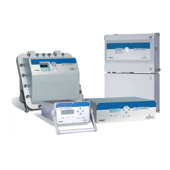
- Page 1 Instruction Manual HASX2E-IM-HS 10/2012 Gas Analyzers X-STREAM X2 Series Instruction Manual www.EmersonProcess.com...
- Page 2 • Read all instructions prior to installing, operating, and servicing the product. • If you do not understand any of the instructions, contact your Emerson Process Management (Rosemount Analytical) representative for clarification. • Follow all warnings, cautions, and instructions marked on and supplied with the product.
- Page 3 ........6 Basic procedures (e.g. calibration) ......7 Maintenance procedures ..........7 Status messages and troubleshooting .....8 Modbus parameters ...........9 Service information ............10 Block diagrams, terminals & connectors ....A Index of phrases ............IDX Emerson Process Management GmbH & Co. OHG TOC-1...
-
Page 4: Table Of Contents
2.2 Model-Specific Technical Data..........2-5 TOC-2 Emerson Process Management GmbH & Co. OHG... - Page 5 5.1 Introduction ............5-1 Emerson Process Management GmbH & Co. OHG...
- Page 6 7.4.5 Unattended Automatic Calibration........7-37 TOC-4 Emerson Process Management GmbH & Co. OHG...
- Page 7 10.3 Training .............10-2 Emerson Process Management GmbH & Co. OHG...
- Page 8 A.7.2 Field Housings............A-38 Index TOC-6 Emerson Process Management GmbH & Co. OHG...
- Page 9 Paramagnetic Oxygen Sensor - Assembly Principle ..........3-5 Fig. 3-5: Electrochemical Sensor - Internal Assembly Principle ...........3-8 Fig. 3-6: Electrochemical O Sensor - Assembly ..............3-8 Fig. 3-7: Electrochemical Reaction of Oxygen Sensor ............3-9 Emerson Process Management GmbH & Co. OHG TOC-7...
- Page 10 Fig. 4-28: Signal Cable With Double Shielding, Shieldings Connected At Alternate Ends. ..4-35 Fig. 4-29: Shield Connector Terminal With Cable ..............4-36 Fig. 4-30: Suppressor Diode for Inductive Loads..............4-37 Fig. 4-31: Driving High-Current Loads ..................4-37 TOC-8 Emerson Process Management GmbH & Co. OHG...
- Page 11 Fig. 7-18: Service Port Connector - Serial RS 232 Interface ..........7-62 Fig. 8-1: X-STREAM X2GP ....................8-19 Fig. 8-2: X-STREAM X2GK ....................8-19 Fig. 8-3: X-STREAM X2 Field Housings and X2FD - How to Open ........8-20 Fig. 8-4: XSP - Allocation of Signal Connectors..............8-21 Emerson Process Management GmbH & Co. OHG TOC-9...
- Page 12 Digital Inputs Priorities ..........7-33 TOC-10 Emerson Process Management GmbH & Co. OHG...
-
Page 13: Introduction
Indicates an operational or maintenance procedure, a process, a condition, an instruction, etc. Failure to comply may result in damage to or destruction of the instrument, or impaired performance. NOTE! Indicates an imperative operational procedure, or an important condition or instruction. Emerson Process Management GmbH & Co. OHG... -
Page 14: Terms Used In This Instruction Manual
(gas) to burn. NAMUR NAMUR is an international user association of automation technology in process industries. This organisation has issued experience re- ports and working documents, called recom- mendations (NE) and worksheets (NA). Emerson Process Management GmbH & Co. OHG... -
Page 15: Symbols Used On And Inside The Unit
Nevertheless several surfaces may remain hot for a limited time. more detailled information available: see in- struction manual before proceeding! more detailled information available: see in- struction manual before proceeding! Emerson Process Management GmbH & Co. OHG... -
Page 16: Symbols Used In This Manual
This symbol may also indicate information impor- tant for achieving accurate measurements. Emerson Process Management GmbH & Co. OHG... -
Page 17: Safety Instructions
• The emission of gases hazardous to health may even be possible when all gas connec- tions have been correctly made. Avoid exposure to the dangers of these residual risks by taking particular care when ins- talling, operating, maintaining and servicing the analyzer. Emerson Process Management GmbH & Co. OHG... -
Page 18: Authorized Personnel
X-STREAM X2 short form manual • HASICx-IM-H Infallible containment instruction manual • Separate manuals for Hazardous Area applications Contact your local service center or sales office when missing documents. SAVE ALL INSTRUCTIONS FOR FUTURE USE! Emerson Process Management GmbH & Co. OHG... -
Page 19: Installing And Connecting The Unit
Connectors may also be energised. The unit should therefore be disconnected from the power supply before any kind of maintenance, repair or calibration work requiring access to the inside of the unit. Emerson Process Management GmbH & Co. OHG... - Page 20 Do not operate without covers secure. Do not open while energized. Installation requires access to live parts which can cause death or serious injury. For safety and proper performace this instrument must be connected to a properly grounded three-wire source of power. Emerson Process Management GmbH & Co. OHG...
- Page 21 Take care the wall or stand the unit is intended to be installed at is solid and stable to support the weight! HIGH TEMPERATURES Hot parts may be exposed when working on photometers and/or heated components in the unit. Emerson Process Management GmbH & Co. OHG...
- Page 22 When operating an instrument at temperatures below 0 °C (32 °F), do NOT apply gas nor operate the internal pump before the warmup time has elapsed! Violation may result in condensation inside the gas paths or damaged pump diaphragm! S-10 Emerson Process Management GmbH & Co. OHG...
- Page 23 If this is not possible, cables must be laid in such a way as to guarantee a clearance of at least 5 mm from power cables. This clearance must be permanently secured (e.g. with cable ties) Emerson Process Management GmbH & Co. OHG S-11...
- Page 24 (CE compliance pursuant to EMC guidelines). In this case the customer or operating company functions as a maker of a system and must therefore ensure and declare compliance with EMC guidelines. S-12 Emerson Process Management GmbH & Co. OHG...
-
Page 25: Chapter 1 Technical Description
Modified resistant measuring cells are avai- measurement of non-flammable gases. lable for use with corrosive gases and/or • Pressurized enclosure conforming to gases containing solvents. ATEX directive 94/9/EC, for installation in zone 2. Emerson Process Management GmbH & Co. OHG... - Page 26 If you intend to use your tions to/from protected internal memory. analyzer for such purposes, we would draw your attention to the separate in- struction manuals supplied with analyzers for use in hazardous areas. Emerson Process Management GmbH & Co. OHG...
-
Page 27: Overview
4x20 character alphanumeric display “Measure“ key LED (red) “Enter” key LED (red) 4 keys for settings and menu navigation LED (green) Fig. 1-1: X-STREAM Front Panel (here the X-STREAM X2GP) Emerson Process Management GmbH & Co. OHG... -
Page 28: Configuration Of Gas Lines
Pipework Unless otherwise specified, the analyzers are supplied with Viton or PVDF piping (ø ® 6/4 mm or ¼ in). Other materials (e.g. stain- less steel) can be used, depending on the application. Emerson Process Management GmbH & Co. OHG... -
Page 29: Optional Components For Gas Lines
6-43). The valves are controlled by Chapter 8 “Troubleshooting”). either a software menu, optionally by digital input, or automatically during autocalibration. Depending on the model, up to two valve bocks can be fitted. Emerson Process Management GmbH & Co. OHG... - Page 30 If such sensors are installed in the unit, this is indicated in the installed options menu 6.2.3.5, page 6-43). Emerson Process Management GmbH & Co. OHG...
-
Page 31: Fig. 1-2: Optional Heated Area
(e.g. of Insulating cover Physical components (example) Heated moun- ting panel Cable support for The figure shows the heated signal wires area with the insulating cover removed. Fig. 1-2: Optional Heated Area Emerson Process Management GmbH & Co. OHG... -
Page 32: Configurations
Depending on the application and the selected analyzer options, several gas line configurati- ons are available, exemplified in the following diagram of a dual-channel analyzer: Fig. 1-3: Gas Flow Diagram: Single Channel or in Series Emerson Process Management GmbH & Co. OHG... -
Page 33: Interfaces
The NE 44 status is also indicated by the LEDs on the front panel. These LEDs remain conformant to NE 44 even when the status relays are assigned different functions by the software. Emerson Process Management GmbH & Co. OHG... -
Page 34: Optional Interfaces
RJ45 socket. This interface is also electrically isolated from the unit’s electronic components and enab- les the construction of a network of several analyzers. All supported Modbus parameters are listed in chapter 9. 1-10 Emerson Process Management GmbH & Co. OHG... - Page 35 Digital inputs can be integrated into the units The inputs are protected against excess in groups of 7 or 14 ( 1.4, page 1-12). voltages of up to approx. 40 V. An open (not wired) input has LOW potential. Emerson Process Management GmbH & Co. OHG 1-11...
-
Page 36: Comparison Of The Various X-Stream X2 Analyzer Models
Weight: ca. 11–16 kg (24–35 lb) For more detailed information: For more detailed information: section 1.5, page 1-14 section 1.6, page 1-16 : Limitations apply to selected measurement principles and ranges, Measurement specifications! 1-12 Emerson Process Management GmbH & Co. OHG... - Page 37 Size: (DxHxW): max. ca. 222x512x578 mm Weight: max. ca. 26 kg (57 lb) Weight: max. ca. 63 kg (138.5 lb) For more detailed information: For more detailed information: section 1.7, page 1-19 section 1.8, page 1-26 Emerson Process Management GmbH & Co. OHG 1-13...
-
Page 38: X-Stream X2Gk: ½19 Inch Table-Top Unit
Interface signals The number of connections varies according to the number of interfaces installed: a 25- 1-14 Emerson Process Management GmbH & Co. OHG... - Page 39 For further information, see page 1-5. which can, for example, be integrated into a measuring system in which control and ana- lysis of data is performed via interface by an external data acquisition system. Emerson Process Management GmbH & Co. OHG 1-15...
-
Page 40: Fig. 1-5: X-Stream X2Gk - Views
DC power input “Measure” key Valve block “Enter” key AC power input with integral fuses and switch 4 keys for adjustment and menu selection Carrying handle Fig. 1-5: X-STREAM X2GK - Views 1-16 Emerson Process Management GmbH & Co. OHG... -
Page 41: X-Stream X2Gp: 19 Inch Table-Top Or Rackmount Design
Service For applications where screw-type terminals Interface. are preferred for connecting signal wires, op- tional adapters are available, which are moun- ted directly onto the submin-D connectors. Emerson Process Management GmbH & Co. OHG 1-17... - Page 42 Further details about the infallible contain- ment are in the separate manual supplied with units containing such parts. 1-18 Emerson Process Management GmbH & Co. OHG...
-
Page 43: Fig. 1-6: X-Stream X2Gp - Views
Signal input/output connectors (some optional) Space for additional tube fittings Optional purge gas inlet Cover for eO or tO sensor Strain-reliefs, top view details Screw-type terminal adapters Strain-reliefs Fig. 1-6: X-STREAM X2GP - Views Emerson Process Management GmbH & Co. OHG 1-19... -
Page 44: X-Stream X2Xf: Field Housing With (Xlf) Single Or (Xxf) Dual Compartment
(Fig. inside the unit, and is designated as a Service 1-8). The front cover of the housing swings Interface. 1-20 Emerson Process Management GmbH & Co. OHG... - Page 45 Furthermore, intrinsically safe measuring cells, which prevent the ignition of gas mixtu- res in the case of a failure, can also be used. Emerson Process Management GmbH & Co. OHG 1-21...
-
Page 46: Fig. 1-7: X-Stream X2Xf Field Housings - Front Views
Take care to use anchors and bolts specified to be used for the weight of the units! Take care the wall or stand the unit is intended to be installed at is solid and stable to support the weight! 1-22 Emerson Process Management GmbH & Co. OHG... -
Page 47: Fig. 1-8: X-Stream X2Xf Field Housings - Front Panel
1.7 X-STREAM X2XF Field Housings 4x20 character alphanumeric display “Measure” key LED (red) “Enter” key LED (red) 4 keys for adjustment and menu selection LED (green) Fig. 1-8: X-STREAM X2XF Field Housings - Front Panel Emerson Process Management GmbH & Co. OHG 1-23... -
Page 48: Fig. 1-9: X-Stream Xlf - Bottom And Side View
Also only 2 brackets are at each com- 4 brackets for wall-mounting partment. Gas in- & outlets (max. 8) Cutouts, to combine 2 housings (here closed) Fig. 1-9: X-STREAM XLF - Bottom and Side View 1-24 Emerson Process Management GmbH & Co. OHG... -
Page 49: Fig. 1-10: X-Stream Xlf - Power Supply And Signal Terminals
Power line filter compartment. Cable glands Power supply terminals with integrated fuses Ethernet connector Fig. 1-10: X-STREAM XLF - Power Supply and Signal Terminals Emerson Process Management GmbH & Co. OHG 1-25... -
Page 50: Field Housing For Installation In Hazardous Areas (Ex-Zones / Divisons)
Equipped with a simplified pressurized enclos- ure, these models can be used to measure non-flammable gases in European Ex-zone 2. A protective gas (e.g. pressurized air) must be supplied when operating this model. 1-26 Emerson Process Management GmbH & Co. OHG... -
Page 51: X-Stream X2Fd: Cast Aluminum Flameproof Housing
The special conditions for installing and operating analyzers in hazardous areas are not covered by this manual! Read the separate instruction manuals shipped together with instrument intended to be installed in hazardous area! Emerson Process Management GmbH & Co. OHG 1-27... - Page 52 EMERSON service personnel or specially trained staff Gas connections Depending on the configuration of the unit (number of channels, series or parallel pi- ping), up to eight flame arresters are provi- 1-28 Emerson Process Management GmbH & Co. OHG...
-
Page 53: Fig. 1-11: X-Stream X2Fd - Front View
Take care to use anchors and bolts specified to be used for the weight of the units! Take care the wall or stand the unit is intended to be installed at is solid and stable to support the weight! Emerson Process Management GmbH & Co. OHG 1-29... -
Page 54: Fig. 1-12: X-Stream X2Fd - Front Panel
Fig. 1-12: X-STREAM X2FD - Front Panel Cable inlets for power and signal cables Gas tube fittings and purge gas outlet 4 brackets for wall mounting Fig. 1-13: X-STREAM X2FD - Bottom View 1-30 Emerson Process Management GmbH & Co. OHG... -
Page 55: Fig. 1-14: X-Stream X2Fd - Terminals
1 Terminals for signal cables (shown fully populated) 4 Power supply terminals with integrated fuses 2 Power line filter 5 Optional Ethernet connection 3 Cable inlets for power and signal cables Fig. 1-14: X-STREAM X2FD - Terminals Emerson Process Management GmbH & Co. OHG 1-31... - Page 56 Instruction Manual X-STREAM X2 HASX2E-IM-HS 10/2012 1-32 Emerson Process Management GmbH & Co. OHG...
-
Page 57: Chapter 2 Technical Data
This chapter contains all the technical details of the analyzers, divided into common and model-specific data. Common technical data page 2-2 X-STREAM X2GK page 2-5 X-STREAM X2GP page 2-11 X-STREAM X2XF (XLF, XXF) page 2-15 X-STREAM X2FD page 2-18 Emerson Process Management GmbH & Co. OHG... - Page 58 UL 61010-1, 2nd edition Europe CE, based on EN 61010-1 Electromagnetic compatitiblity Europe CE, based on EN 61326 Australia C-Tick others NAMUR Gas parameters Chapter 3 “Measuring principles” Purging options 4.3 "Gas Conditioning" Emerson Process Management GmbH & Co. OHG...
- Page 59 NAMUR NE 107 status signal “Failure” “Maintenance request” “Out of specification” “Function check” 1 of 2 concentration limits per channel, Control signals for external valve V1…V8, external sample gas valve external pump Zoom status for analog outputs Emerson Process Management GmbH & Co. OHG...
-
Page 60: Common Technical Data
“Failure” “Maintenance request” “Out of specification” “Function check” 1 of 2 concentration limits per channel, Control signals for external valve V1…V8, external sample gas valve external pump Zoom status display for analog outputs Emerson Process Management GmbH & Co. OHG... -
Page 61: Model-Specific Technical Data
X-STREAM X2 HASX2E-IM-HS 10/2012 2.2.1 Model-Specific Technical Data: X-STREAM X2GK 2.2 Model-Specific Technical Data 2.2.1 X-STREAM X2GK: ½19 Inch Table-Top Unit All dimensions in mm [inches in brackets] Fig. 2-1: X-STREAM X2GK - Dimensions Emerson Process Management GmbH & Co. OHG... -
Page 62: Fig. 2-2: X-Stream X2Gk - Rear Panel And Handle Variations
Frame and handle detail Portable standard digital Ethernet AC supply valve block with handle Note! All shown variable options are interchangable! Fig. 2-2: X-STREAM X2GK - Rear Panel and Handle Variations Emerson Process Management GmbH & Co. OHG... - Page 63 As standard, signal cables are connected using Submin-D plugs or sockets on the unit’s rear panel (except Ethernet: RJ45 socket) ( Fig. 2-2) Detailed terminal configuration 4.4.1 Installation, page 4-7. : Limitations apply to selected measurement principles and ranges, Measurement specifications! Emerson Process Management GmbH & Co. OHG...
- Page 64 Resets after cooling. Weight approx. 2.5 kg (4.8 lb) Certification Safety EN 60950, UL1950, CSA22.2 NO 950-95 EN 50081-1 (emitted interference) EN 50082-2 (interference resistance), et al. Emerson Process Management GmbH & Co. OHG...
-
Page 65: Fig. 2-3: Ups 01 T Power Supply Unit
Pin 2: + 24 V Pin 3: 0 V (⊥) shield: housing flange Pin configuration for 24 V DC output socket Dimensions (approx. values in [mm]) Fig. 2-3: UPS 01 T Power Supply Unit Emerson Process Management GmbH & Co. OHG... -
Page 66: Fig. 2-4: 10 A Table-Top Psu
85–132 / 176–264 V , 47–63 Hz Nominal input current < 6 A (input voltage set to 115V) < 2,8 A (input voltage set to 230V) Connection via rubber connector (IEC connector) with fuse holder ( Fig. 2-4). 2-10 Emerson Process Management GmbH & Co. OHG... - Page 67 60° C (140 °F) Certification (for internal power supply module only) Safety EN 60950, EN 50178, UL1950, CUL/CSA-22.2 No 950-M90 EN 50081-1, class B (emitted interference) EN 50082-2, class A (interf. resistance), et al. Emerson Process Management GmbH & Co. OHG 2-11...
-
Page 68: X-Stream X2Gp: 19 Inch Table-Top And Rack-Mount Models
X: Height of rear panel cover for tO2 cell: 10 mm [0.39] Strain relief eO2 cell: 36 mm [1.42] bracket, detail (model with clamping adapt- ers) Fig. 2-5: X-STREAM X2GP - Dimensions 2-12 Emerson Process Management GmbH & Co. OHG... - Page 69 (IEC connector) with power switch at rear of unit ( figs. 2-5 & 2-6). Power input fuses The IEC connector incorporates holders for two fuses. Data for fuse links: AC 230 V / T 4 A / 5x20 mm Emerson Process Management GmbH & Co. OHG 2-13...
-
Page 70: Fig. 2-6: X-Stream X2Gp - Power Supply And Signal Connections
X-STREAM X2GP - Power Supply and Signal Connections Strain relief with cable shield grounding clamps (quantity varies depending on installed options) Terminal adapters Terminal adapters (detail) Fig. 2-7: X-STREAM X2GP - Signal Connections With Screw-Type Terminal Adapters (top View) 2-14 Emerson Process Management GmbH & Co. OHG... -
Page 71: X-Stream X2Xf: Single (Xlf) Or Dual (Xxf) Compartment Field Housing
X-STREAM X2XF: Single (XLF) or Dual (XXF) Compartment Field Housing Gas fittings Cable glands Connector for potential equalization All dimensions in mm [inches in bra- ckets] Fig. 2-8: X-STREAM XLF - Dimensions Emerson Process Management GmbH & Co. OHG 2-15... -
Page 72: Fig. 2-9: X-Stream Xxf - Dimensions
X-STREAM X2 HASX2E-IM-HS 10/2012 2.2.3 Model-Specific Technical Data: X-STREAM X2XF Field Housings All dimensions in mm [inches in brackets] Gas fittings Connector for potential equalization Cable glands Fig. 2-9: X-STREAM XXF - Dimensions 2-16 Emerson Process Management GmbH & Co. OHG... - Page 73 Fuse holders are integrated within power supply terminals Data for fuse links: AC 230 V / T 6.3 A / 5x20 mm : Limitations apply to selected measurement principles and ranges, Measurement specifications! Emerson Process Management GmbH & Co. OHG 2-17...
-
Page 74: Fig. 2-10: X-Stream X2Xf Field Housings - Power Supply Terminals / Fuse Holders
Analog & digital I/O terminal strips Depending on the actual analyzer configuration Max. 4 signal cables entries not all shown terminals may be installed! Fig. 2-11: X-STREAM X2XF Field Housings - Signal Terminals 2-18 Emerson Process Management GmbH & Co. OHG... -
Page 75: X-Stream X2Fd: Flameproof Housing
Gas connections: quantity: max. 8 specification: flame arresters w. fittings connections: 6/4 mm or ⁄ “, stainless steel : Limitations apply to selected measurement principles and ranges, Measurement specifications! Emerson Process Management GmbH & Co. OHG 2-19... -
Page 76: Fig. 2-13: X-Stream X2Fd - Power Supply Terminals / Fuse Holders
AC 230 V / T 4 A / 5x20 mm Power terminals with integrated fuse holders Protective earth terminal (PE) Power cable entry EMI power supply filter Fig. 2-13: X-STREAM X2FD - Power Supply Terminals / Fuse Holders 2-20 Emerson Process Management GmbH & Co. OHG... -
Page 77: Fig. 2-14: X-Stream X2Fd - Signal Terminals
Detailed terminal configuration separate model X-STREAM X2FD instruction manual ad- dendum. Note! Depending on the actual analyzer configuration not all shown terminals may be installed! Fig. 2-14: X-STREAM X2FD - Signal Terminals Emerson Process Management GmbH & Co. OHG 2-21... -
Page 78: Information On Name Plate
6 Channel 4: Gas and full scale ranges (here:O , 5 to 25 %) 7 Manufacturer´s address 8 Certification marks (XEGK, XEGP: on a separate label) 9 Electrical data (XEGK, XEGP: on rear panel) Fig. 2-15: Analyzer Name Plate (examples) 2-22 Emerson Process Management GmbH & Co. OHG... -
Page 79: Chapter 3 Measuring Principles
The assembly of a NDIR and NDUV channel modulated with 4 and 5 times the basic revo- is shown in Fig. 3-3. For NDIR a broad- lution frequency. As a result, the proof peak Emerson Process Management GmbH & Co. OHG... -
Page 80: Fig. 3-1: Intrinzx Signal Forms
Fig. 3-1: IntrinzX signal forms plications: • One bench enables measurements of low & high ranges • Low & high concentration in raw and clean gases Emerson Process Management GmbH & Co. OHG... -
Page 81: Ndir Detector
Gas flows back from the (now) hotter compensation chamber into the absorption chamber. The Absorption chamber Window Fill nozzle Compensation chamber Connecting channel with micro flow detector Fig. 3-2: Gas detector design principle Emerson Process Management GmbH & Co. OHG... -
Page 82: Technical Implementation
9 Temperature sensor 4 Filter cell 10 Filter for pyro detector assembly 5 UV detector 11 Chopper 6 Gas detector 12 Chopper electronics 13 IR source 14 EDL Fig. 3-3: Photometer assembly principle Emerson Process Management GmbH & Co. OHG... -
Page 83: Oxygen Measurement
5 Loop So the current compensating the torque 11 Gas outlet affec-ting the dumbbell is a direct measure for the oxygen concentration within the sample Fig. 3-4: Paramagnetic oxygen sensor - gas. Assembly principle Emerson Process Management GmbH & Co. OHG... -
Page 84: Tab. 3-1: Paramagnetic Sensor - Cross Interferences (Examples)
Hydrogen +0.26 Vinyl chloride -0.77 Hydrogen bromide -0.76 Water -0.03 Xenon -1.05 Note! This data is based on a temperature of 60 °C (140 °F). Tab. 3-1: Paramagnetic sensor - cross interferences (examples) Emerson Process Management GmbH & Co. OHG... -
Page 85: Tab. 3-2: Solvent Resistant Paramagnetic Sensor - Approved Solvents
For the solvent resistant version of this cell, the ‘O’ ring made of viton is replaced by a Tab. 3-2: Solvent resistant paramagnetic sensor - approved solvents chemraz model. ® Emerson Process Management GmbH & Co. OHG... -
Page 86: Electrochemical Measurement
7 Titanum wire into holder 8 O-Ring 9 Pressure compensating volumes 10 Lid 11 Electrical connections 12 Lids 13 Current collector Fig. 3-6: Electrochemical O Sensor - assembly Fig. 3-5: Electrochemical Sensor Internal Assembly Principle Emerson Process Management GmbH & Co. OHG... -
Page 87: Fig. 3-7: Electrochemical Reaction Of Oxygen Sensor
In this case the sensor must be halves lifetime). replaced to ensure accurate measurements Chapter 7 "Maintenance"). Increases or decreases in atmospheric pres- sure have the same effect as increasing or decreasing oxygen concentrations. Emerson Process Management GmbH & Co. OHG... -
Page 88: Fig. 3.8 Cover For Eo2 Sensor Block At Rear Panel
Note for X2GP analyzers! If the X2GP analyzer features a thermostate control, the eO2 sensor block is installed at the X2GP rear panel. Cover Fig. 3.8 Cover for eO2 sensor block at rear panel 3-10 Emerson Process Management GmbH & Co. OHG... -
Page 89: Electrochemical Trace Oxygen Measurement
O + O → 4OH sult in a damaged sensor! in total: 2P b + O → 2P bO Prolonged exposure of the sensor to air can cause extended start up time, reduction of Emerson Process Management GmbH & Co. OHG 3-11... -
Page 90: Fig. 3.10 Cover For To2 Sensor Block At Rear Panel
Note for X2GP analyzers! If the X2GP analyzer features a thermostate control, the tO2 sensor block is installed at the X2GP rear panel. Cover Fig. 3.10 Cover for tO2 sensor block at rear panel 3-12 Emerson Process Management GmbH & Co. OHG... -
Page 91: Thermal Conductivity Measurement
2 sensors are located in the sample gas stream (R ) and Fig. 3-11: Wheatstone Bridge in a reference gas stream (R Fig. 3-11. Emerson Process Management GmbH & Co. OHG 3-13... -
Page 92: Technical Implementation
3 PT 100 sensors 4 Metal block 4 Metal block 5 Heater for thermostatting 5 Lid Fig. 3-13: TC cell, sectional view Fig. 3-12: TC cell, exterior view , thermal isolation removed 3-14 Emerson Process Management GmbH & Co. OHG... -
Page 93: Trace Moisture Measurement
If the dew point remains constant and temperature increases, relative humidity will decrease. Emerson Process Management GmbH & Co. OHG 3-15... -
Page 94: Special Operating Conditions
10.8 3306 14.1 3856 18.3 4487 23.5 5208 30.2 6030 38.5 6964 48.9 8025 61.8 9226 77.6 10 583 97.1 12 113 Tab. 3-6: Dew Points and Water Content (at 1013 hPa) 3-16 Emerson Process Management GmbH & Co. OHG... -
Page 95: Accompanying Gases
– Methanol no limit Methylethyl glycol no limit no limit Natural gas no limit no limit Nitric acid Nitrogen dioxide no limit Nitrous oxide no limit Tab. 3-7: Limitations on Gases Emerson Process Management GmbH & Co. OHG 3-17... - Page 96 Consult with EMERSON for extremely sour natural gas, >1 % H Consider sacrificial gold filter to remove mercury vapour – Consult with EMERSON. Consult with EMERSON - for impedance type sensors, recommended concentration limit of Methanol <10% of moisture concentration to be measured to ensure negligible interference effects.
-
Page 97: Measurement Specifications
In total, more than 60 gases are detectable, so the following table gives an overview only. Consult with Emerson for gases / configurations not listed. Not all data is applicable to all analyzer variations. The sample gas(es) and measuring ranges for your specific analyzer are given by the order acknowledgement and on the analyzer's name plate label. -
Page 98: Tab. 3-9: Ir, Uv, Vis, Tcd - Measurement Performance Specifications
All performance data is verified during the manufacturing process for each unit by the following tests: • Linearization and sensitivity test • Long term drift stability test • Climate chamber test • Cross interference test (if applicable) 3-20 Emerson Process Management GmbH & Co. OHG... -
Page 99: Tab. 3-10: Oxygen - Standard Measurement Performance Specifications
A remedy for this issue is to purge the housing with gas not containing the component of interest. Emerson Process Management GmbH & Co. OHG 3-21... -
Page 100: Tab. 3-11: Trace Moisture - Standard Measurement Performance Specifications
Limited to atmospheric if internal sample pump From gas analyzer inlet at gas flow of 1.0 l/min Special conditions apply to model X2FD Tab. 3-12: Special Performance Specifications for Gas Purity Measurements 3-22 Emerson Process Management GmbH & Co. OHG... -
Page 101: Chapter 4 Installation
Trace oxygen DC power cable • infallible containment instruction manual cell (X2GK, option) (if applicable) Fig. 4-1: X-STREAM X2 Analyzers - scope of supply Emerson Process Management GmbH & Co. OHG... -
Page 102: Introduction
(e.g. housing. Submin-d plugs and sockets must European EMC guidelines). be screwed to the analyzer. Emerson Process Management GmbH & Co. OHG... -
Page 103: Gas Conditioning
The X-STREAM field housings can optionally be fitted with heated piping to enable the use of gases with a maximum dew point of 25 °C (77 °F). Emerson Process Management GmbH & Co. OHG... - Page 104 Measuring Principles“ within this manual. analyzer components, if due to Perform a calibration each time a leak released into the analyzer the source of this gas (e. g. enclosure! bottle) has changed! Emerson Process Management GmbH & Co. OHG...
-
Page 105: Gas Connections
The sensor must be installed before analyzer startup, according the instructions shipped with the sensor! Do not use plastic tubing for trace oxygen measurements as it can permeate oxygen from the ambient air and cause higher than expected oxygen readings. Emerson Process Management GmbH & Co. OHG... -
Page 106: Fig. 4-2: Labelling Of Gas Connectors (Example)
Exhaust Analyzer Exhaust Pressure control valve Flow sensor Filter Sample gas pump Fig. 4-3: Installation in bypass mode Emerson Process Management GmbH & Co. OHG... -
Page 107: Electrical Connections
Any break in the earth wire inside or outside the unit may cause exposure to the risk of electrocution and is therefore prohibited. Emerson Process Management GmbH & Co. OHG... -
Page 108: Analyzer Specific Instructions For Installation
Even if you do not install your X-STREAM X2FD in an EX zone, please install the unit according to the instructions in the separate manual. Installation instructions: X-STREAM X2GK page 4-8 X-STREAM X2GP page 4-14 X-STREAM X2XF Field housings page 4-22 Notes for wiring signal inputs and outputs page 4-33 Emerson Process Management GmbH & Co. OHG... -
Page 109: X-Stream X2Gk
Six screws at the front panel enable to install X2GK models into a rack. The external PSU is optionally available for rack mounting, too. Fig. 4-4: X-STREAM X2GK - front panel Emerson Process Management GmbH & Co. OHG... -
Page 110: Fig. 4-5: X-Stream X2Gk - Rear Panel
Gas connections: Quantity: max. 8 of which optional 1 or 2 as purge gas connections Material: PVDF 6/4 mm optional Stainless steel 6/4 mm or ⁄ ", others on request 4-10 Emerson Process Management GmbH & Co. OHG... -
Page 111: Fig. 4-6: Socket X1 - Pin Configuration
Output3 (Off spec) NO Output4 (Function check) COM Output3 (Off spec) COM Note! Configuration of relay contacts as per standard factory setting (NAMUR status signals) Fig. 4-6: Socket X1 - Pin configuration Emerson Process Management GmbH & Co. OHG 4-11... -
Page 112: Fig. 4-7: Plug X2 - Modbus Interface
D0(-) TXD0(-) not used Fig. 4-7: Plug X2 - Modbus interface Notes! Consider the installation notes in section 4.5. X-STREAM analyzers are classified as DTE (Data Terminal Equipment). 4-12 Emerson Process Management GmbH & Co. OHG... -
Page 113: Fig. 4-8: Socket X4 - Pin Configuration
Output 13, NC Output 8, NC Output 13, NO 22, are on the second socket Output 8, NO Output 13, COM (X4.2), if installed. Output 8, COM Fig. 4-8: Socket X4 - Pin configuration Emerson Process Management GmbH & Co. OHG 4-13... -
Page 114: Fig. 4-9: Power In Connectors
2.2.1.1, page 2-8ff. AC power is supplied to the unit by means of a three-pin IEC connector on the rear panel of the instrument. AC supply Fig. 4-9: Power In Connectors 4-14 Emerson Process Management GmbH & Co. OHG... -
Page 115: X-Stream X2Gp
(Fig. 4-12). Screw holes for rack mounting (7.5 x 10.5 mm) Fig. 4-10: X-STREAM X2GP - front view Emerson Process Management GmbH & Co. OHG 4-15... -
Page 116: Fig. 4-11: X-Stream X2Gp - Rear Panel, Model With Signal Plugs And Sockets
Gas inlets and outlets Quantity: max. 8 (plus. 1 purge gas inlet (optional)) Specification: 6/4 mm PVDF optional 6/4 mm or ⁄ ", stainless steel, others on request 4-16 Emerson Process Management GmbH & Co. OHG... -
Page 117: Fig. 4-12: X-Stream X2Gp - Rear Panel, With Terminal Adapters And Brackets
Instruction Manual X-STREAM X2 HASX2E-IM-HS 10/2012 4.6.2 Installation - X-STREAM X2GP Fig. 4-12: X-STREAM X2GP - Rear panel, with terminal adapters and brackets for rack mounting Emerson Process Management GmbH & Co. OHG 4-17... - Page 118 Output3 (Off spec) NO Output4 (Function check) COM Output3 (Off spec) COM Note! Configuration of relay contacts as per standard factory setting (NAMUR status signals) Fig. 4-13: Socket X1 - Analog & Digital Outputs 1-4 4-18 Emerson Process Management GmbH & Co. OHG...
-
Page 119: Fig. 4-14: Plug X2 - Modbus Interface
Fig. 4-15, page 4-20). Then a flat flexible cable attached to the ter- minal adapter is used for connecting to the illustrated 9-pole plug. Emerson Process Management GmbH & Co. OHG 4-19... -
Page 120: Fig. 4-15: Configuration Of Xsta Terminal Adapter
2 Connection for flat cable to plug X2 (cable not illustrated) P4.12 D0(-) TXD0(-) not used 3 Screw-type terminals Note! Consider the installation notes in section 4.5. Fig. 4-15: Configuration of XSTA terminal adapter 4-20 Emerson Process Management GmbH & Co. OHG... -
Page 121: Fig. 4-16: Sockets X4.1 And X4.2 - Pin Configuration
Output 8, NC Output 13, NO 23, are on the second socket Output 8, NO Output 13, COM (X4.2), if installed. Output 8, COM Fig. 4-16: Sockets X4.1 and X4.2 - Pin configuration Emerson Process Management GmbH & Co. OHG 4-21... -
Page 122: Fig. 4-17: Configuration Of Xstd Terminal Adapter
P2.12 Output 13, COM 1 Connector for socket X4.1 / X4.2 (on reverse side) 2 Screw-type terminals Note! Consider the installation notes in section 4.5. Fig. 4-17: Configuration of XSTD terminal adapter 4-22 Emerson Process Management GmbH & Co. OHG... -
Page 123: X-Stream X2Xf Field Housings (Single Xlf; Dual Xxf)
Take care to use anchors and bolts specified to be used for the weight of the instruments! Assure that the wall/device for installation is sufficiently attached and stable to carry the instrument! Emerson Process Management GmbH & Co. OHG 4-23... -
Page 124: Fig. 4-19: X-Stream Xxf
Take care to reserve space at the right side of the instru- ment for laying the cables! Gas fittings Connector for potential equalization Cable glands All dimensions in mm [inches in brackets] Fig. 4-19: X-STREAM XXF 4-24 Emerson Process Management GmbH & Co. OHG... - Page 125 3 Power connections with integrated fuses 7 Plugs for openings to connect housings 4 Gland for power cable 8 Ethernet connector (optional) Fig. 4-20: X-STREAM X2XF Field Housings - Arrangement of Terminals, Cable Glands and Gas Fittings Emerson Process Management GmbH & Co. OHG 4-25...
- Page 126 Feed cable through dome nut and clam- ping insert Fold braided shield over clamping insert Make sure that brai- ded shield overlaps the O-ring by ⁄ “ (2 mm) 4-26 Emerson Process Management GmbH & Co. OHG...
- Page 127 Verify the power cord is layed with a distance of at least 1 cm (0.4 in) to any signal cable to ensure proper insulation from signal circuits! Emerson Process Management GmbH & Co. OHG 4-27...
- Page 128 Serial Interface Relay Outputs Analog Outputs Configuration of relay output termi- nals as per standard factory setting (NAMUR status signals) Fig. 4-21: Terminal block X1 - Analog signals and relay outputs 1-4 4-28 Emerson Process Management GmbH & Co. OHG...
-
Page 129: Fig. 4-22: Terminal Block X1 - Modbus Interface
P4.11 RXD0(-) ked on a label nearby the terminals not used not used P4.12 D0(-) TXD0(-) not used (see sample above) Fig. 4-22: Terminal block X1 - Modbus interface Emerson Process Management GmbH & Co. OHG 4-29... -
Page 130: Fig. 4-23: X-Stream X2Xf Field Housings - Ethernet Connector
Please note that although the Modbus termi- nals ( previous page) are still installed, they are not connected! Pin 1 Pin 8 Pin no. Signal other used Fig. 4-23: X-STREAM X2XF Field Housings - Ethernet connector 4-30 Emerson Process Management GmbH & Co. OHG... -
Page 131: Fig. 4-24: Terminal Blocks For Digital Inputs And Outputs
Inputs 8-14 and outputs 14-23, if available, are on the second adapter. Digital outputs Digital inputs Fig. 4-24: Terminal blocks for digital inputs and outputs Emerson Process Management GmbH & Co. OHG 4-31... -
Page 132: Fig. 4-25: Power Supply Connections
Finally, tighten the outer dome nut to secure the power cable. Power supply Live L cable gland Neutral N Earth PE Fig. 4-25: Power supply connections 4-32 Emerson Process Management GmbH & Co. OHG... - Page 133 For this reason we recom- mend to carry out a leak test, as it is described within Chapter 7 "Maintenance and other Procedures". Emerson Process Management GmbH & Co. OHG 4-33...
-
Page 134: Notes On Wiring Signal Inputs And Outputs
• We recommend using only shielded signal cables. The shielding must be connected at both ends to the housing (Fig. 4-26). Fig. 4-26: Shielded signal cable, shielding connected at both ends. 4-34 Emerson Process Management GmbH & Co. OHG... -
Page 135: Fig. 4-27: Shielded Signal Cable, Shielding Connected At One End
This is advan- tageous when both units are supplied from different grids (e.g. when installed in different buildings). Fig. 4-28: Signal cable with double shielding, shieldings connected at alternate ends. Emerson Process Management GmbH & Co. OHG 4-35... -
Page 136: Fig. 4-29: Shield Connector Terminal With Cable
Ø 1.5 - 6.5 mm: part # ETC02019 Ø 5 - 11 mm: part # ETC02020 Ø 10 - 17 mm: part # ETC02021 Ø 16 - 24 mm: part # ETC02022 4-36 Emerson Process Management GmbH & Co. OHG... -
Page 137: Wiring Inductive Loads
(Fig. 4-30). Last Compatible filter components for standard valves are available on request. External relay Analyzer output Fig. 4-31: Driving high-current loads Fig. 4-30: Suppressor diode for inductive loads. Emerson Process Management GmbH & Co. OHG 4-37... -
Page 138: Driving Multiple Loads
4-33). Interference is further reduced if a twisted multi-core cable is used. Fig. 4-32: Loads in series Lay cables to the loads together as far as possible (using twisted-pair cables if possible) Fig. 4-33: Loads in parallel 4-38 Emerson Process Management GmbH & Co. OHG... -
Page 139: Chapter 5 Startup
When operating an instrument at temperatures below 0 °C (32 °F), do NOT apply gas nor operate the internal pump before the warmup time has elapsed! Violation may result in condensation inside the gas paths or damaged pump diaphragm! Emerson Process Management GmbH & Co. OHG... -
Page 140: Front Panel Elements
(currently available: English, French, German, Italian, Portuguese and Spanish in various combinations). Fig. 5-1: X-STREAM Front Panel Emerson Process Management GmbH & Co. OHG... -
Page 141: Display
A flashing red LED in the middle indicates “Maintenance request”, “Function check” or “Off-spec operation”. The third, green LED indicates the power supply status: on: power supply OK off: power supply interrupted Emerson Process Management GmbH & Co. OHG... -
Page 142: Keys
UP / DOWN keys: Mode Function Leaves the measurement dis- Measuring play Selects menu line Goes to previous/next page, Browsing when currently in a line begin- ning with / Editing Changes current parameter Emerson Process Management GmbH & Co. OHG... - Page 143 showing in first line RIGHT key: Mode Function Measuring Leaves the measurement display Browsing Accesses submenu (..) Goes to next page, when showing in fourth line Editing Moves cursor 1 space Emerson Process Management GmbH & Co. OHG...
-
Page 144: Symbols Used
Adv. Calibration.. background are optional or Apply gas.. context-dependent, and are not always displayed Access levels: Access level 1 (user) Access level 2 (expert) Access level 3 (administrator) Access level 4 (service level) Emerson Process Management GmbH & Co. OHG... -
Page 145: Software
If a selected parameter has been changed, If the cursor is in the first line, pressing the the “function check” status is set, with the key will move it to the last line. following consequences: Emerson Process Management GmbH & Co. OHG... - Page 146 • It is not possible to select the minus sign or decimal point as the last character. • It is not possible to select the decimal point in integer values. Emerson Process Management GmbH & Co. OHG...
-
Page 147: Access Levels
In this chapter, the descriptions of the indi- deactivated), all lower levels will also be au- vidual menus also indicate which level the tomatically unlocked. menus are in. These assignments cannot be changed. Emerson Process Management GmbH & Co. OHG... -
Page 148: Special Messages
Confirms that a procedure (e.g. calibration) valid limits. The display indicates what limits has been aborted. apply. Pressing 8 returns the display to the previous screen to allow a valid setting to be entered. 5-10 Emerson Process Management GmbH & Co. OHG... -
Page 149: Powering Up
Line 4 is also used to display plain text status information (errors, maintenance requests, function checks or off-spec performance). If such messages are active, line 4 alternates between the messages and the parameter selected for line 4. Emerson Process Management GmbH & Co. OHG 5-11... -
Page 150: Selecting The Language
ENTER will set this language and the display is updated accordingly. If the selected language is not the intended one, the previous three steps can be repeated until the intended language is set. 5-12 Emerson Process Management GmbH & Co. OHG... -
Page 151: Checking The Settings
3 out of below list of available languages. Language Currently available (may be extended by future software versions.): Language: EN: English, FR: French, DE: German, IT: Italian, ES: Spanish, PT: Portuguese Emerson Process Management GmbH & Co. OHG 5-13... -
Page 152: Installedoptions
Pressure: Internal performance of the unit. Analog outputs This initial access to this menu More.. is intended to gain information on the configuration of the unit. Page 2 5-14 Emerson Process Management GmbH & Co. OHG... - Page 153 Baud rate: 19200 protocol to be used for data transfer. Parity: Pressing the LEFT key twice will return you to the SETUP menu. Emerson Process Management GmbH & Co. OHG 5-15...
-
Page 154: Configuring The Display
Set temperature unit Temperature Options available: °C, °F Unit: °C Set number of decimal places for temperature DecimalPlaces: display: 0 to 4 Temp-1 63.7 °C Current temperature; here: sensor 1. 5-16 Emerson Process Management GmbH & Co. OHG... -
Page 155: Calibration Setup
If the concentration varies by more than 10% of the range from the value set, the calibration is aborted. Emerson Process Management GmbH & Co. OHG 5-17... - Page 156 Valve assignment.. tup. Interval time.. If any of these parameters need to be changed, section 7.3 at page 7-3 for Page 2 more information. 5-18 Emerson Process Management GmbH & Co. OHG...
- Page 157 The factory setting is 0 seconds. and any value between 0 and 28 seconds can be set. In multi-channel units, the value for each channel must be entered separately. Emerson Process Management GmbH & Co. OHG 5-19...
-
Page 158: Setting The Analog Outputs
4 mA is sent. This allows the detection of a severed cable. This (life zero) mode is activated by setting the “SignalRange” parameter to 4-20 mA. 5-20 Emerson Process Management GmbH & Co. OHG... -
Page 159: Tab. 5-1: Analog Output Signals: Settings And Operational Modes
(20.01 ... 21.5 mA)** Note! The application of values marked * or ** depends on the setting of "SignalRange" Analog outputs menu, page 6-31). Tab. 5-1: Analog Output Signals: Settings and Operational Modes Emerson Process Management GmbH & Co. OHG 5-21... - Page 160 Output1.. output parameters to be set. The number of Output2.. lines displayed will depend on the number of Output3.. available anaogue outputs. All these subme- Output4.. nus are identical: Page 2 5-22 Emerson Process Management GmbH & Co. OHG...
- Page 161 (C1 to C4). If one of these options Zoom-C1, Zoom-C2, Zoom-C3, Zoom-C4 is selected, the “Zoom..” line appears in the menu (see above), which allows a zoom to be set. Emerson Process Management GmbH & Co. OHG 5-23...
- Page 162 This function allows a part of the signal range, specified by “LowScale” and “HighScale”, to be “magnified” on the analog output. Unlike the scaling function, here the output is swit- ched automatically, the moment the switching point concentration is reached. 5-24 Emerson Process Management GmbH & Co. OHG...
- Page 163 1 and 99 % of the range previously set in the “LowScale” and “HighScale” functions. Additionally, the “Position” parameter allows the X-STREAM analyzer to zoom either the Emerson Process Management GmbH & Co. OHG 5-25...
- Page 164 Switch point (“Zoom” parameter applied range centration centration from HighScale ) 0 ... 20 mA 2 mA 0 mA Concentration 4 ... 20 mA 5,6 mA 4 mA 5-26 Emerson Process Management GmbH & Co. OHG...
- Page 165 Parameter "LowScale" Scaling different 0 2500 settings, 4000 5000 where tables are NOT Parameter "HighScale" applicable lower than "MinRange" Parameter "HighScale" 5100 higher than "MinRange" Tab. 5-2: Analog Outputs - Scaling (examples) Emerson Process Management GmbH & Co. OHG 5-27...
-
Page 166: Setting Concentration Alarms
Should the measured concentration go bey- ond one of the limits, a message is displayed in the fourth line of the measurement display and the corresponding digital output is acti- vated if programmed to do so. 5-28 Emerson Process Management GmbH & Co. OHG... -
Page 167: Tab. 5-3: Influence Of "Spanrange" Parameter On Concentration Alarm Limits
10 % 100 ppm -100 ppm 1100 ppm Example 4 (see text) 220 % 120 % 1200 ppm -1200 ppm 2200 ppm Tab. 5-3: Influence of “SpanRange” Parameter on Concentration Alarm Limits Emerson Process Management GmbH & Co. OHG 5-29... - Page 168 Window mode: An alarm is triggered, if the concentration drops below or exceeds the limits of a concentration window, . • High pre-alarm and main alarm: A pre- alarm and a main alarm are set for rising concentrations. 5-30 Emerson Process Management GmbH & Co. OHG...
-
Page 169: Fig. 5-2: Limits Defining A Window For Valid Concentrations
Status message on front panel If an alarm is active, a corresponding mes- sage is displayed in line 4 of the measurement Fig. 5-2: Limits Defining a Window for display. valid Concentrations Emerson Process Management GmbH & Co. OHG 5-31... -
Page 170: Fig. 5-3: High Pre-Alarm And Main Alarm
Level 2-Function: High FS Status message on front panel If an alarm is active, a corresponding mes- sage is displayed in line 4 of the measurement Fig. 5-3: High Pre-Alarm and Main Alarm display. 5-32 Emerson Process Management GmbH & Co. OHG... -
Page 171: Fig. 5-4: Low Pre-Alarm And Main Alarm
Level 2-Function: Low FS Status message on front panel If an alarm is active, a corresponding mes- sage is displayed in line 4 of the measurement Fig. 5-4: Low Pre-Alarm and Main Alarm display. Emerson Process Management GmbH & Co. OHG 5-33... -
Page 172: Backing Up The Settings
Page 1 Press the DOWN key to reach page 2. FactData > CfgData.. Now select the “CfgData > UserData” line and CfgData > UserData.. press ENTER. UserData > CfgData.. Page 2 5-34 Emerson Process Management GmbH & Co. OHG... - Page 173 For more detailed descriptions of all the ope- rations in this menu: 7.6, page 7-51. You have now completed checking the analyzer setup: Press the MEASURE key to return to the measurement display. Emerson Process Management GmbH & Co. OHG 5-35...
- Page 174 Instruction Manual X-STREAM X2 HASX2E-IM-HS 10/2012 5-36 Emerson Process Management GmbH & Co. OHG...
-
Page 175: Chapter 6 User Interface And Software Menus
While all the software menues are described in this chapter, chapters 5 and 7 explain by use of examples how to navigate through the menus to perform certain basic setup opera- tions or other functions. Emerson Process Management GmbH & Co. OHG... -
Page 176: Symbols Used
Apply gas.. pendent on context, and so may not always be displayed. Menu access: Level 1 (User) Level 2 (Expert) Level 3 (Administrator) Level 4 (Service level) Emerson Process Management GmbH & Co. OHG... -
Page 177: Menu System
Notes! This figure applies to software revision 1.x and later. Numbers are page numbers of this manual, where the associated menu is explained. Fig. 6-1: X-STREAM Software menu structure Emerson Process Management GmbH & Co. OHG... -
Page 178: Startup
The following submenus are available from Measurement Display here: Control menu 6.2.2, page 6-5 Control.. Setup.. Setup menu 6.2.3, page 6-14 Status.. Info.. Status menu 6.2.4, page 6-50 MAIN Menu Info menu 6.2.5, page 6-61 Emerson Process Management GmbH & Co. OHG... - Page 179 6-39) or when no internal pump is available. Zoom submenu 6.2.2.6, page 6-13 Note! The zoom function for at least 1 analog output must be activated for this line to appear ( 6.2.3.4.1, page 6-31). Emerson Process Management GmbH & Co. OHG...
- Page 180 Current measured gas concentration. Multi-channel unit: Note! Press the key to enter the SELECT COM- For further details on calibration procedures, PONENT menu to change the settings for a chapter 7 Maintenance. different channel. Emerson Process Management GmbH & Co. OHG...
- Page 181 Current measured gas concentration. Multi-channel unit: Note! Press the key to enter the SELECT COM- For further details on calibration procedures, PONENT menu to change the settings for a chapter 7 Maintenance. different channel. Emerson Process Management GmbH & Co. OHG...
- Page 182 Unless altered by the user, UserData settings are the same as the factory settings. Note 2! Once the reset procedure is started, a mes- sage is displayed indicating how to abort the procedure. Emerson Process Management GmbH & Co. OHG...
- Page 183 The first line indicates the currently used gas. Gasflow Spangas This line shows the concentration currently CO.1 13.304 ppm measured. Procedure None Time Indicates which procedure is active (None, Purging, Zeroing, Spaning). Time remaining for completion of active pro- cedure. Emerson Process Management GmbH & Co. OHG...
- Page 184 4th line will allow the operator to start a zero and a span calibration with a single keypress. Note! For further details on calibration procedures, chapter 7 Maintenance. 6-10 Emerson Process Management GmbH & Co. OHG...
- Page 185 (with the exception of Time None, which closes all valves). Multi-channel unit: Press the key to enter the SELECT COMPONENT menu to change the settings for a different channel. Emerson Process Management GmbH & Co. OHG 6-11...
- Page 186 Acknowledgements All status messages are acknowledged and reset here: simlpy press the 8 key, to ack- Status! nowledge messages. A short confirmation is displayed after this procedure. -COMMAND EXECUTED- 6-12 Emerson Process Management GmbH & Co. OHG...
- Page 187 These settings merely switch the zoom func- tion for each channel on or off. To edit the zoom function settings (e.g. zoom factor, etc.), use the corresponding menu for analog output settings ( 6.2.3.4.1.2.1, page 6-36). Emerson Process Management GmbH & Co. OHG 6-13...
- Page 188 In/Output setup 6.2.3.4, page 6-30 Installed options 6.2.3.5, page 6-43 Communication setup Installed options. 6.2.3.6, page 6-45 Communication.. Alarms.. Alarms setup Save-Load.. 6.2.3.7, Seite 6-46 Page 2 Save-Load 6.2.3.8, Seite 6-48 6-14 Emerson Process Management GmbH & Co. OHG...
- Page 189 Press-1 ... Press-4, Line 4: Comp-4 Flow-1 ... Flow-4 Page 2 Blank (nothing) Note! X-STREAM currently only supports one pres- sure sensor. The values Press-1...Press-4 therefore all relate to the same sensor. Emerson Process Management GmbH & Co. OHG 6-15...
- Page 190 X-STREAM currently only supports one pres- sure sensor. The values Press-1...Press-4 therefore all relate to the same sensor. Note! If a 2 measurement display page has been configured, use the LEFT/RIGHT keys to switch between both pages. 6-16 Emerson Process Management GmbH & Co. OHG...
- Page 191 DE: German IT: Italian ES: Spanish PT: Portuguese PL: Polish Note! Each analyzer is shipped with 3 out of above listed available languages. This list may be extended by future software versions.: Emerson Process Management GmbH & Co. OHG 6-17...
- Page 192 6.2.2, pg. 6-5), sets all active locks. Code 1: 00000001 Code 2: 00000002 Code 3: 00000003 Defines access codes for the corresponding levels. Page 2 The illustration shows the factory settings. 6-18 Emerson Process Management GmbH & Co. OHG...
- Page 193 Texts for tags and units, and values for factor PONENT menu to change the settings for a and offset are not checked for plausibility. Any different channel. arbitrary value can be set.. Emerson Process Management GmbH & Co. OHG 6-19...
- Page 194 Set pressure value Available options: Pressure Pa, hPa, mbar, Bar, psi Unit: DecimalPlaces: Set number of places after decimal point for Pressure 998.1 hPa pressure value: 0 to 4 Current presssure value 6-20 Emerson Process Management GmbH & Co. OHG...
- Page 195 Gasflow Available options: l/h, l/min, mlmin Unit: DecimalPlaces: Set number of places after decimal point for Flow-1 63.7 l/h gas flow value: 0 to 4 Current gas flow, here: Sensor 1 value Emerson Process Management GmbH & Co. OHG 6-21...
- Page 196 For further details on calibration procedures, chapter 7 Maintenance. Possible values: 0 .. 600 seconds 6-22 Emerson Process Management GmbH & Co. OHG...
- Page 197 "valves" in the INSTALLED OPTIONS menu is set to other than none. Assign valves 6.2.3.2.2, page 6-26 Valve assignment.. Interval time.. Set interval time for calibration 6.2.3.2.3, page 6-26 Page 2 Emerson Process Management GmbH & Co. OHG 6-23...
- Page 198 Multi-channel unit: Press the key to enter the SELECT COM- PONENT menu to change the settings for a different channel. 6-24 Emerson Process Management GmbH & Co. OHG...
- Page 199 • Combinations in which one valve has the ency using such combinations. same function for several channels "7.3 Calibration Procedures" at page 7-5). Emerson Process Management GmbH & Co. OHG 6-25...
- Page 200 6.2.3.2.3.1, page 6-27 Note! This line appears if at least one interval time has been set. Note! For further details on calibration procedures, chapter 7 Maintenance. 6-26 Emerson Process Management GmbH & Co. OHG...
- Page 201 Note! In case there is an interval time specified for one procedure only (ZeroAll or ZSCalAll; 6.2.3.2.3, page 6-26), the related lines for the other procedure will be hidden in this menu!. Emerson Process Management GmbH & Co. OHG 6-27...
- Page 202 Pressure: 1014.0 hPa As the pressure value is used for pressure Damping.. compensation, it should, when set to Manu- al, be regularly updated to ensure accurate results. Setup signal damping 6.2.3.3.1, page 6-29 6-28 Emerson Process Management GmbH & Co. OHG...
- Page 203 The analyzer’s total delay time (t time) is the sum of the signal damping time and the physical time lag caused e.g. by the properties of the gas flow and the sensors. Emerson Process Management GmbH & Co. OHG 6-29...
- Page 204 6-43) IntSHS menu 6.2.3.4.4, page 6-39 Note! This menu line appears only if the parameter in the INSTALLED OPTIONS - VALVES menu is set to Internal or Int+Ext ( 6.2.3.5, page 6-43 6-30 Emerson Process Management GmbH & Co. OHG...
- Page 205 Note! This behaviour may be problematic if, for ex- ample, the instrument is connected to a data acquisition system. Emerson Process Management GmbH & Co. OHG 6-31...
-
Page 206: Tab. 6-1: Analog Output Signals - Settings And Operational Modes
20.5 mA* 4-20 mAH similar Live-Zero above 4 ... 20 mA > 21.7 mA 0 mA (2.2 ...3.9 mA)** (20.01 ... 21.5 mA)** Tab. 6-1: Analog output signals - settings and operational modes 6-32 Emerson Process Management GmbH & Co. OHG... - Page 207 System failures thus cannot be detected by am external data acqui- sition system. NE 43 contains recommendations for setting analog outputs in order to avoid these situa- Emerson Process Management GmbH & Co. OHG 6-33...
- Page 208 (20 mA). This submenu sets the zoom function for the analog output; 6.2.3.4.1.2.1, page 6-36 Note! The last line only appears when "signal" is set to a zoom value (e.g. Zoom-C1). 6-34 Emerson Process Management GmbH & Co. OHG...
- Page 209 If "signal" was set to 20mA select the 4 line to trim (finetune) the analog output to exactly provide 20 mA. Accepted values: -1000 ... +1000 (corresponding to appr. -1 ... +1 mA) Emerson Process Management GmbH & Co. OHG 6-35...
- Page 210 Available options: LowScale, HighScale Current zoom function status. Available options: On, Off Note! Further details on the function and setting up of the zoom function can be found in Chapter 5 Startup. 6-36 Emerson Process Management GmbH & Co. OHG...
- Page 211 Page 3 Output13: Lim2Cmp1 Further pages are indicated by a down arrow ) only when a second extension card (out- puts 14 - 22) is installed. Page 4 Emerson Process Management GmbH & Co. OHG 6-37...
-
Page 212: Tab. 6-2: Options For Digital Outputs
Component (channel) 3 analog signal is zoomed Zoom4 Component (channel) 4 analog signal is zoomed FlowAlm Alarm by flow sensor FLimAlm1 Alarm by flow monitor 1 FLimAlm2 Alarm by flow monitor 2 Tab. 6-2: Options for Digital Outputs 6-38 Emerson Process Management GmbH & Co. OHG... - Page 213 Page 2 Input8: Input9: Sample Inputs 8 - 14 are available on the second Input10: Pump extension card. Input11: ZeroAll Page 3 Input12: SpanAll Input13: Zoom1 Input14: Zoom2 Page 4 Emerson Process Management GmbH & Co. OHG 6-39...
-
Page 214: Tab. 6-3: Options For Digital Inputs
Enables connection and use of an external digital gas flow FlowAlm alarm Tab. 6-3: Options for Digital Inputs Chapter 7 includes detailed descriptions of the configuration and execution of calibra- tions with valves. 6-40 Emerson Process Management GmbH & Co. OHG... - Page 215 Pump1: Pump installed pumps can be set. Pump2: Note Depending on the model, up to 2 pumps may be installed. Page 3 For an overview of all available options: next page. Emerson Process Management GmbH & Co. OHG 6-41...
-
Page 216: Tab. 6-4: Parameter Intshs Options
“Gas1” to “Gas8”. Double assignments are possible, but only meaningful if the unit is configured accordin- gly. Chapter 7 includes detailed descriptions of the configuration and execution of calibra- tions with valves. 6-42 Emerson Process Management GmbH & Co. OHG... - Page 217 Internal: Internal pressure sensor installed. External: Pressure sent via network (e.g. Page 2 DeltaV) Indicates how many analog outputs are in- stalled. Accepted values: 1 ... 4 More sensors 6.2.3.5.1 page 6-44). Emerson Process Management GmbH & Co. OHG 6-43...
- Page 218 Available options: None, Flow-1, Flow-2 Multi-channel unit: Press the key to enter the SELECT COM- PONENT menu to select a different channel. 6-44 Emerson Process Management GmbH & Co. OHG...
- Page 219 AB234CDE56 None, Even, Odd Note! To view first 2 lines, set "Interface" to other Page 2 than Ether MAC ID of the Ethernet port (visible only if "Interface" is set to Ether) Emerson Process Management GmbH & Co. OHG 6-45...
- Page 220 Off, Low, High, Off FS, Low FS, High FS is taken from the corresponding line in the Chapter 5 includes more details about DISPLAY SETUP menu ( 6.2.3.1.3, page these options and alarm settings) 6-19). 6-46 Emerson Process Management GmbH & Co. OHG...
- Page 221 Relay is de-energized if flow is below given limit. Multi-channel unit: Press the key to enter the SELECT COM- PONENT menu to change the settings for a different channel. Emerson Process Management GmbH & Co. OHG 6-47...
- Page 222 This line initiates the procedure for an online comparison of the current configuration data with the data stored via the service port. The current configuration is not overwritten. Downloaded data are deleted on completion of this procedure. 6-48 Emerson Process Management GmbH & Co. OHG...
- Page 223 If an error occurs, the user data are loaded into RAM, overwri- ting the CfgData configuration. This ensures that the instrument is always ready for use. Chapter 7 includes further details of the Save-Load functions. Emerson Process Management GmbH & Co. OHG 6-49...
- Page 224 6.2.4.6, page 6-58 Page 2 Alarm status 6.2.4.7, page 6-60 Zoom1 Indicates whether zoom is active for the ana- Zoom2 log outputs. ( 6.2.3.4.1.2.1, page 6-36) Zoom3 Zoom4 Page 3 6-50 Emerson Process Management GmbH & Co. OHG...
- Page 225 Select the component in the SELECT COM- PONENT menu. ADC-Error Chopper Detector Source Page 2 Multi-channel unit: Press the key to enter the SELECT COM- PONENT menu to select a different channel. Emerson Process Management GmbH & Co. OHG 6-51...
- Page 226 PONENT menu. ZCalTolChk SCalTolCh ZCalRefused SCalRefused Page 2 FlowMonAlm Page 3 Multi-channel unit: Press the key to enter the SELECT COM- PONENT menu to select a different channel. 6-52 Emerson Process Management GmbH & Co. OHG...
- Page 227 The corresponding relay is also activated, if configured for NAMUR error messages. Calibration SvcPort > Cf (e.g.: a calibration is currently in progress) NotSampleGas Warm-up Page 1 LocalAccess Simulation Page 2 Emerson Process Management GmbH & Co. OHG 6-53...
- Page 228 Select the component in the SELECT COM- PONENT menu. TempRange RangeOverflo TempSensor Multi-channel unit: Press the key to enter the SELECT COM- PONENT menu to select a different channel. Page 2 6-54 Emerson Process Management GmbH & Co. OHG...
- Page 229 AutoCal in.. Purging: purging gas lines Page 1 The third line indicates the time remaining for the currently active procedure. This submenu displays information about the next autocalibration ( 6.2.4.5.1, page 6-57) Emerson Process Management GmbH & Co. OHG 6-55...
- Page 230 Page 2 Multi-channel unit: Press the key to enter the SELECT COM- PONENT menu to select a different channel. Note! For more detailed information about calibrati- on status, Chapter 7 Maintenance. 6-56 Emerson Process Management GmbH & Co. OHG...
- Page 231 & span calibration. Note! In case there is an interval specified for one procedure only (ZeroAll or ZSCalAll; 6.2.3.2.3, page 6-26), the related lines for the other procedure will be hidden!. Emerson Process Management GmbH & Co. OHG 6-57...
- Page 232 Displays the current pressure, either from Pressure 1014 hPa an internal or external sensor or manually entered. 6.2.3.5, page 6-43 for more information on how pressure is measured. Page 2 6-58 Emerson Process Management GmbH & Co. OHG...
- Page 233 Source current values are shown only Multi-channel unit: if this limit is not yet reached. Press the key to enter the SELECT COM- PONENT menu to select a different channel. Emerson Process Management GmbH & Co. OHG 6-59...
- Page 234 (e.g.. CO.1 Alarm Level1). Multi-channel unit: Press the key to enter the SELECT COM- PONENT menu to open the same menu for a different channel. 6-60 Emerson Process Management GmbH & Co. OHG...
- Page 235 This line only appears if a pump is available! Page 2 Factory settings 6.2.5.3, page 6-64 Europe.. Addresses for customer services: select a line North America.. to obtain contact information for the region. Latin America.. Asia-Pacific.. Page 3 Emerson Process Management GmbH & Co. OHG 6-61...
- Page 236 Displays the maximum permitted span gas factor for the upper range value ( chap- ter 7, Calibration procedures). Multi-channel unit: Press the key to enter the SELECT COM- PONENT menu to select a different channel. 6-62 Emerson Process Management GmbH & Co. OHG...
- Page 237 Page 2 6.2.5.2.1 below 6.2.5.2.1 Installed options, more information Info.. Installed Options.. More.. Multi-channel unit: Select another component in the SELECT COMPONENT menu to see the options for this channel. FlowSensor TempSensor Temp-1 Emerson Process Management GmbH & Co. OHG 6-63...
- Page 238 For this reason, access to this level is protected with a level 4 code and granted only to spe- cially trained personnel. The code for access level 4 must be entered to gain access to this menu. 6-64 Emerson Process Management GmbH & Co. OHG...
-
Page 239: Chapter 7 Maintenance And Other Procedures
Perform a leak test 7.3, page 7-4 Perform a calibration 7.4, page 7-5 Replacing Worn Out sensors 7.5, page 7-43 Clean the instrument´s outside 7.6, page 7-54 Backup / restore configuration data sets 7.7, page 7-55 Emerson Process Management GmbH & Co. OHG... -
Page 240: General Maintenance Information
Once a year Flame arrestors Corrosion, damages, firmly seated Corrosion, damages on enclosure and Field housings (IP 66 / NEMA 4X) gaskets Field housings stopping plugs Firmly seated Field housings cable glands Firmly seated Emerson Process Management GmbH & Co. OHG... - Page 241 Depending on output signal (see details later in this sec- Electrochemical oxygen cell tion) Filter, internal Once a year, at least when contaminated Filter, external Several times a year, depending on process conditions Emerson Process Management GmbH & Co. OHG...
-
Page 242: Performing A Leak Test
Max. pressure 7.25 psig must not change over a time period of (500 mbar)! approx. 5 minutes! Multi channel instruments: Analyzers with parallel tubing require separate leak tests for each gas path ! Emerson Process Management GmbH & Co. OHG... -
Page 243: Calibration Procedures
It is the operators responsibility to not perform a span calibration without a preceding zero calibration! Advanced calibration Advanced calibration is a more comfortable variation of manual calibration, providing ONE KEY calibrations supported by internal and/ Emerson Process Management GmbH & Co. OHG... - Page 244 1 l/min), and utilizing the correct gas fitting. Ensure the warm-up time after switching on has elapsed! Warm-up time depends on installed measuring system and configuration, measurement specifications in chapter 3! Emerson Process Management GmbH & Co. OHG...
- Page 245 Multi-channel unit: Press the key to enter the SELECT COM- PONENT menu to change the settings for a different channel. When done, press the key to return to the CALIBRATION menu. Emerson Process Management GmbH & Co. OHG...
- Page 246 In addition: If, for example, a calibration was the tolerance check is enabled somewhere aborted because of a tolerance check, the in the future! maintenance request is active. If the operator Emerson Process Management GmbH & Co. OHG...
- Page 247 Hold on cal: ons only ( 7.3.1.1.4, page 7-14). Purge time: 15 s If you do not intend to carry out valve sup- ported calibrations, continue with 7.3.2, page 7-15. Emerson Process Management GmbH & Co. OHG...
-
Page 248: Fig. 7-2: Calibration Improvement By Variable Valve Assignments
Zero spanning with fixed assignment ch1 & improvement Zero spanning with & & in time variable assignment timeline Fig. 7-2: Calibration Improvement by Variable Valve Assignments 7-10 Emerson Process Management GmbH & Co. OHG... - Page 249 COM-Interf: stalled, valve assignment has to be done Pump: utilizing both, the INTSHS ( 7.3.1.1.1 Flow monitor: page 7-10) and the DIGITAL OUTPUTS menu 7.3.1.1.2 page 7-12). Emerson Process Management GmbH & Co. OHG 7-11...
- Page 250 The number of available gas connections Gas7: depends on the analyzer model and varies Gas8: from 4 to 8. If already factory setup, changing the confi- Page 2 guration could result in inproper operation! 7-12 Emerson Process Management GmbH & Co. OHG...
-
Page 251: Fig. 7-3: Internal Valves Assignments
Internal Valves Assignments The next step is to assign the internal valves to the channels. If there are no external valves to be controlled by your analyzer, continue with 7.3.1.1.3 page 7-13. Emerson Process Management GmbH & Co. OHG 7-13... - Page 252 Note! Depending on the analyzer model, 1 or 2 Digital I/O extension cards can be installed. The next step is to assign the valves to the channels: Continue with 7.3.1.1.3 page 7-13. 7-14 Emerson Process Management GmbH & Co. OHG...
- Page 253 Entries in this lines are not checked to be pro- PONENT menu to change the settings for a per: The user has to ensure not to configure different channel. a valve that has not been installed! Emerson Process Management GmbH & Co. OHG 7-15...
- Page 254 Note! Regardless of how many valves are installed, only one single purge time can be specified! Enter the longest time applicable to any of the installed valves! 7-16 Emerson Process Management GmbH & Co. OHG...
- Page 255 7-21 ADV.CALIBRATION - ZSCALALL! Remote calibration n.a. (via Modbus or Dig IN) recommended all channels page 7-32 Unattended calibration n.a. (via interval time) required all channels page 7-37 Emerson Process Management GmbH & Co. OHG 7-17...
- Page 256 ZeroGas 0.000 ppm Line 3 shows the calibration gas setup CO2.1 0.200 ppm (here: required zero gas concentration is 0.000 ppm), while line 4 shows the currently measured gas concentration. 7-18 Emerson Process Management GmbH & Co. OHG...
- Page 257 START calibration! Line 3 shows the calibration gas setup (here: SpanGas 20.000 ppm required span gas concentration is 20 ppm), CO2.1 16.200 ppm while line 4 shows the currently measured gas concentration. Emerson Process Management GmbH & Co. OHG 7-19...
- Page 258 HOME key to return to the measurement screen to finish with manual calibration pro- cedures. 7-20 Emerson Process Management GmbH & Co. OHG...
- Page 259 For a description of how to perform all channel zero calibrations 7.4.3.1, page 7-22 all channel span calibrations 7.4.3.2, page 7-25 all channel zero & span calibrations 7.4.3.3, page 7-28 Emerson Process Management GmbH & Co. OHG 7-21...
- Page 260 To start a ZERO calibration for ALL channels Cancel calibration! select the second line. ZeroAll! Note! SpanAll! ZeroSpanAll! Single channel analyzers show the same menu, with the restriction, that the term "ALL" relates to the single channel only! 7-22 Emerson Process Management GmbH & Co. OHG...
-
Page 261: Fig. 7-4: Zero All Calibration Procedure Flow Chart
1 is this channel already zeroed? Fig. 7-4: Zero All Calibration Procedure Flow Chart Emerson Process Management GmbH & Co. OHG 7-23... - Page 262 0 seconds and the gas flow is sample. Now press either the LEFT key to return to the advanced calibration menu to select another calibration procedure or the HOME key to return to the measuring screen. 7-24 Emerson Process Management GmbH & Co. OHG...
- Page 263 To start a SPAN calibration for ALL channels Cancel calibration! select the third line. ZeroAll! Note! SpanAll! ZeroSpanAll! Single channel analyzers show the same menu, with the restriction, that the term "ALL" relates to the single channel only! Emerson Process Management GmbH & Co. OHG 7-25...
-
Page 264: Fig. 7-5: Span All Calibration Procedure Flow Diagram
1 is this channel already spanned? Fig. 7-5: Span All Calibration Procedure Flow Diagram 7-26 Emerson Process Management GmbH & Co. OHG... - Page 265 0 seconds and the gas flow is sample. Now press either the LEFT key to return to the advanced calibration menu to select another calibration procedure or the HOME key to return to the measuring screen. Emerson Process Management GmbH & Co. OHG 7-27...
- Page 266 To start a ZERO & SPAN calibration for ALL Cancel calibration! channels select the last line. ZeroAll! Note! SpanAll! ZeroSpanAll! Single channel analyzers show the same menu, with the restriction, that the term "ALL" relates to the single channel only! 7-28 Emerson Process Management GmbH & Co. OHG...
-
Page 267: Fig. 7-6: Zero Span All Calibration Procedure Flow Diagram
1 by 1 is this is this channel channel already already zeroed? spanned? Fig. 7-6: Zero Span All Calibration Procedure Flow Diagram Emerson Process Management GmbH & Co. OHG 7-29... - Page 268 (zero gas). Once all channels are zero calibrated, auto- matically a span calibrate all channels proce- dure is started: 7-30 Emerson Process Management GmbH & Co. OHG...
- Page 269 The span calibration procedure has finished when the last time interval shows remaining 0 seconds and the gas flow is sample. Now press the HOME key to return to the measuring screen. Emerson Process Management GmbH & Co. OHG 7-31...
- Page 270 For detailled descriptions on how to perform calibrations initialized via digital inputs 7.4.4.1, page 7-30 calibrations initialized via Modbus, without valves 7.4.4.2, page 7-32 calibrations initialized via Modbus, with valves 7.4.4.3, page 7-33 7-32 Emerson Process Management GmbH & Co. OHG...
-
Page 271: Tab. 7-1: Digital Inputs Priorities
If ALL valves are closed, the pump is work as an inhibit signal for future calibra- always switched off automatically, regard- tion signals. less of how it is controlled. Emerson Process Management GmbH & Co. OHG 7-33... -
Page 272: Fig. 7-7: Digital Inputs - Initializing Calibrations
Example 2: Signal C initializes a SpanAll calibration. Signal F is applied during the ongoing procedure and cancels it after the minimum 2 seconds duration. Fig. 7-7: Digital Inputs - Initializing Calibrations 7-34 Emerson Process Management GmbH & Co. OHG... - Page 273 If applicable, he also has to take care to not activate a span calibration without a preceding zero calibration. For detailled instructions about manual cali- bration 7.3.2, page 7-15. Emerson Process Management GmbH & Co. OHG 7-35...
- Page 274 Zero and span calibrate all channels. The analyzer controls the gas flow, if appli- cable optimizes the sequence of multiple calibrations and takes care to not activate a span calibration without a preceding zero calibration. 7-36 Emerson Process Management GmbH & Co. OHG...
- Page 275 4) (multi channel instruments only): Every time an unattended calibration is started, it is carried out for all channels! Emerson Process Management GmbH & Co. OHG 7-37...
-
Page 276: Fig. 7-8: Graphical Explanation Of Interval Time Settings
T2 Span calibrations, preceded by zero ZeroAll: T1 calibrations (time interval T2), and ZSCalAll: T2 additional zero calibrations (time interval T1) Fig. 7-8: Graphical Explanation of Interval Time Settings 7-38 Emerson Process Management GmbH & Co. OHG... - Page 277 ZSCalAll calibrations are now activated 1:00 a.m. every day, 9:55 a.m. every day with the first procedure to be carried out early (first procedure carried out the next day). the next day. Emerson Process Management GmbH & Co. OHG 7-39...
-
Page 278: Resetting A Calibration
CONTROL.. menu. Enter the last line (APPLY GAS..) Zero calibration.. Span calibration.. Adv. calibration.. Apply gas.. Multi-channel unit: Select the component to be verified in the SELECT COMPONENT menu. 7-40 Emerson Process Management GmbH & Co. OHG... -
Page 279: Cancelling An Ongoing Calibration
Cancelling during postpurge does not influ- ence the procedure because the new data has already been calculated and stored, and the (post-)purge time cannot be shortened (except by changing the related setup menu parameter). Emerson Process Management GmbH & Co. OHG 7-41... - Page 280 CO2.1 0.000 ppm supported calibration was cancelled: The Procedure Purging moment, the sample valve was opened, a Time 10 s postpurge procedure was started. Press the LEFT key to exit these screens. 7-42 Emerson Process Management GmbH & Co. OHG...
- Page 281 (e.g. instruments with earth connectors, heating installations). This should be done periodically when working at open instruments (especially after leaving the service site, because e.g. walking on low conducting floors might cause additional ESD). Emerson Process Management GmbH & Co. OHG 7-43...
-
Page 282: Replacing Worn Out Sensors
• remove the 4 screws for the cover, (2 screws on each side of the instrument • push the cover towards the rear and re- move it. Fig. 7-10: X-STREAM X2GK 7-44 Emerson Process Management GmbH & Co. OHG... -
Page 283: Fig. 7-11: X-Stream X2 Field Housings And X2Fd - How To Open
Consider that enclosure gaskets may be frozen if the instrument is installed outdoors. Carefully open the enclosure at temperatures below -10 °C to not damage the gaskets. Damaged gaskets void the ingress protection, possibly causing property damage, personal injury or death. Emerson Process Management GmbH & Co. OHG 7-45... - Page 284 Replacing Worn Out Sensors Separate sections describe the replacement of the various sensors: Electrochemical oxygen sensor 7.5.3, page 7-46 Trace oxygen sensor (tO 7.5.4, page 7-53 Trace moisture sensor 7.5.4, page 7-54 7-46 Emerson Process Management GmbH & Co. OHG...
-
Page 285: Replacing The Electrochemical Oxygen Sensor
If the electrolyte leaks due to sensor damage, put the sensor in a plastic bag so that the solution will not be smeared on other places and return the sensor to Emerson Process Management or an industrial waste management contractor. - Page 286 Do not disassemble or repair the sensor. Removing a sensor part or remodeling the sensor will damage the sensor or leak the electrolyte and restoration to the original condition may not be possible. 7-48 Emerson Process Management GmbH & Co. OHG...
- Page 287 1 digital volt meter (measuring range ) for less than 1 h (e.g. for analyzer zero- 0…2 V dc minimum) with suitable cables ing purpose) has no influence on measuring and probes. characteristics. Emerson Process Management GmbH & Co. OHG 7-49...
-
Page 288: Fig. 7-12: Location Of The Eo2 Sensor Unit
1 eO2 sensor Unit 2 Cover for rear panel installation Fig. 7-12: Location of the EO2 Sensor Unit If your analyzer features the eO2 sensor at the rear panel, continue with page 7-51. 7-50 Emerson Process Management GmbH & Co. OHG... -
Page 289: Fig. 7-13: Sensor Unit Design
3 Holder 7 Screws Now re-assemble the sensor unit in reverse 4 Base Plate 8 Clip order, but do not yet install it into the analyzer as it requires a signal adjustment. Emerson Process Management GmbH & Co. OHG 7-51... -
Page 290: Fig. 7-14: Sensor At Rear Panel
Once the output signal has been adjusted Strip P3 for sensor connection for a specific sensor, further changing the potentiometer settings will cause incorrect measuring results! Fig. 7-15: OXS Board, Top View 7-52 Emerson Process Management GmbH & Co. OHG... - Page 291 To ensure proper disposal, send back the old sensor to the EMERSON Process Manage- ment factory (or to your local sales office) or to an industrial waste management contractor for waste disposal. Emerson Process Management GmbH & Co. OHG 7-53...
-
Page 292: Replacing The Trace Oxygen Sensor
A new sensor will be provided together with detailled installation and handling instructions. Consider all information given by the replacement instructions to avoid damaging the sensor, and to achieve best possible life time! 7-54 Emerson Process Management GmbH & Co. OHG... -
Page 293: Replacing The Trace Moisture Sensor
30 mm Sensor block Connectors: 1 sensor signal plug 2 power to sensor 3 signal to analyzer For details see appendix! Fig. 7-16: Trace Moisture Sensor Assembly Separated Emerson Process Management GmbH & Co. OHG 7-55... -
Page 294: Cleaning The Instrument´s Outside
Moisten the lint-free cloth with a mixture of • Clean the analyzer housing outside with 3 parts of water and 1 part of the general the moistened cloth. purpose detergent. • If need be dry the housing after cleaning. 7-56 Emerson Process Management GmbH & Co. OHG... -
Page 295: Save / Restore Configuration Data Sets
So, as CfgData is overwritten by UserData in case of a checksum failure, it is recommended to store the CfgData once the instrument is setup to the operator‘s needs, to ensure, the analyzer setup is not lost. Emerson Process Management GmbH & Co. OHG 7-57... -
Page 296: Fig. 7-17: Relationship Of Supported Data Sets And Where To Find Further Information
(CfgData --> UserData, on user request 7.6.1, page 7-53) (UserData --> CfgData, 7.6.2, page 7-54) UserData configuration saved to FRAM Fig. 7-17: Relationship of Supported Data Sets and Where to Find Further Information 7-58 Emerson Process Management GmbH & Co. OHG... -
Page 297: Save Cfgdata To Userdata
Any further changes affecting the instrument's setup update the CfgData only, as long as not manually saved to the UserData set. When the procedure has finished, the COM- MAND EXECUTED screen shows up. -COMMAND EXECUTED- Emerson Process Management GmbH & Co. OHG 7-59... -
Page 298: Restore Userdata To Cfgdata
MAND EXECUTED screen shows up for 2 seconds, followed by... ... the previous menu page. After a few se- FactData > CfgData.. conds the analyzer automatically starts to CfgData > UserData.. reboot. UserData > CfgData.. 7-60 Emerson Process Management GmbH & Co. OHG... -
Page 299: Copy Factdata To Cfgdata
MAND EXECUTED screen shows up for 2 seconds, followed by... ... the previous menu page. After a few se- FactData > CfgData.. conds the analyzer automatically starts to CfgData > UserData.. reboot. UserData > CfgData.. Emerson Process Management GmbH & Co. OHG 7-61... -
Page 300: Save / Restore Cfgdata To External Device
The fixed (not operator editable) settings for the interface are Baudrate 19200 Startbit Parity Even Stopbit MODB mode 32 Bit ID number MODB mode may be changed via related Modbus register 7-62 Emerson Process Management GmbH & Co. OHG... - Page 301 - PLEASE WAIT - (and possibly changed by operator) analyzer setup on an external device for future use. Procedure <--> When the procedure has finished, the COM- -COMMAND EXECUTED- MAND EXECUTED screen shows up. Emerson Process Management GmbH & Co. OHG 7-63...
- Page 302 CfgData. SvcPort > CfgData.. Finally a status screen shows up, followed by Verify! a COMMAND EXECUTED screen or an error message, if the data does not match. 7-64 Emerson Process Management GmbH & Co. OHG...
- Page 303 MAND EXECUTED screen shows up for 2 -COMMAND EXECUTED- seconds, followed by…. Save-Load … the previous menu page. After a few se- CfgData > SvcPort! conds the analyzer automatically starts to SvcPort > CfgData.. reboot. Verify! Emerson Process Management GmbH & Co. OHG 7-65...
- Page 304 Instruction Manual X-STREAM X2 HASX2E-IM-HS 10/2012 7-66 Emerson Process Management GmbH & Co. OHG...
-
Page 305: Chapter 8 Troubleshooting
8.2 Problems Indicated by Status Messages Analyzer Related Messages page 8-3 Channel Related Messages page 8-6 8.3 Problems NOT Indicated by Status Messages page 8-11 8.4 Extended Troubleshooting on Components page 8-17 Emerson Process Management GmbH & Co. OHG... -
Page 306: Solving Problems Indicated By Status Messages
(e.g. during calibration). If solving a reported problem requires working inside an open instrument, take care of the safety instructions given at the beginning of this manual! Emerson Process Management GmbH & Co. OHG... - Page 307 Explanation: inside or outside the instru- The internal pressure ment If applicable check internal control detected a pump function pressure problem Emerson Process Management GmbH & Co. OHG...
-
Page 308: Analyzer Related Messages
XSP board SensCmdFail Failure Bandwidth, currently available Acknowledge the message. If for data exchange with XSP Explanation: recurring, call for service. board, too small Sending a command to XSP board failed Emerson Process Management GmbH & Co. OHG... - Page 309 SVC port in use Unlinear Off-spec Instrument has been set to Switch off diagnostic mode Explanation: "unlinear mode" by service (Modbus command) This message does not personnel (see "simulation") appear during operation modes! Emerson Process Management GmbH & Co. OHG...
-
Page 310: Channel Related Messages (Preceded By Channel Tag, E.g. Co2.1)
Chopper is not working properly Detector Failure Either output signal too small Check output signal or replace or distorted, or preamp is Explanation: component defective Preamp is not working properly Emerson Process Management GmbH & Co. OHG... - Page 311 Disable tolerance check before from setpoint) (first calibration after installa- restarting the calibration tion) ZCalRefused Check request Wrong DSP (sensor) configu- Explanation: Call for service ration This message does not appear during normal operation modes! Emerson Process Management GmbH & Co. OHG...
- Page 312 Explanation: Concentration alarm level 1 is activated (exceeded) Alarm Level2 Adjust the gas concentration Alarm level 2 was exceeded to be within the set limits Explanation: Concentration alarm level 2 is activated (exceeded) Emerson Process Management GmbH & Co. OHG...
- Page 313 Function check shed Explanation: Zero calibration ongoing for Ongoing zero calibration the channel identified by the Note! Cancel calibration In the status menu this message shows up in the "Calibration" line without channel tag! Emerson Process Management GmbH & Co. OHG...
- Page 314 Instruction Manual X-STREAM X2 HASX2E-IM-HS 10/2012 8.2.2 Channel Related Messages 8-10 Emerson Process Management GmbH & Co. OHG...
- Page 315 (XLF; XXF) or downwards (X2FD). To do so loosen the four nuts fixing the front panel to the door and swivel the front panel using the remaining srews as hinges. Emerson Process Management GmbH & Co. OHG 8-11...
- Page 316 Digital outputs not working XPSA: If red LED "TIMEOUT" properly glows - check connection to Outputs 1 - 4 affected XPSA: LED "TIMEOUT" dark - check power connection to XPSA (2-pole cable br/wht) 8-12 Emerson Process Management GmbH & Co. OHG...
-
Page 317: Solving Problems Not Indicated By Status Messages
- check power connection to XPSA (2-pole cable br/wht) Valves connected to digital See "Digital outputs not wor- outputs king properly" External valves not working properly Valves not connected to digital Check external valve control- outputs Emerson Process Management GmbH & Co. OHG 8-13... - Page 318 Exchange both source in case fective of dual channel analyzer / replace source if need be (see service manual) Check measuring point Analog preamplifier of af- fected channel defective 8-4-2-1-6, page 8-19) 8-14 Emerson Process Management GmbH & Co. OHG...
- Page 319 Pump rate too low model with higher pump rate too long (operate in bypass mode, fig. 4-2, page 4-4) Check gas path and sample Gas path(s) polluted handling system for pollution Clean gas path Emerson Process Management GmbH & Co. OHG 8-15...
- Page 320 / defective Replace solenoid valves For valve control via serial interface or digital inputs: Any valve activated? Check gas path and sample Gas path(s) polluted handling system for pollution Clean gas path 8-16 Emerson Process Management GmbH & Co. OHG...
-
Page 321: Troubleshooting On Components
8-36 ELECTRICAL SHOCK HAZARD Working at opened and powered instruments means working near live parts and is subject to instructed and trained personnel only! Take care to observe all applicable safety instructions! Emerson Process Management GmbH & Co. OHG 8-17... - Page 322 (e.g. instruments with earth connectors, heating installations). This should be done periodically when working at open instruments (especially after leaving the service site, because e.g. walking on low conducting floors might cause additional ESD). 8-18 Emerson Process Management GmbH & Co. OHG...
- Page 323 • remove the 4 screws for the cover, (2 screws on each side of the instrument • push the cover towards the rear and re- move it. Fig. 8-2: X-STREAM X2GK Emerson Process Management GmbH & Co. OHG 8-19...
-
Page 324: Fig. 8-3: X-Stream X2 Field Housings And X2Fd - How To Open
Consider that enclosure gaskets may be frozen if the instrument is installed outdoors. Carefully open the enclosure at temperatures below -10 °C to not damage the gaskets. Damaged gaskets void the ingress protection, possibly causing property damage, personal injury or death. 8-20 Emerson Process Management GmbH & Co. OHG... -
Page 325: Signal Connectors On Xsp Board
Instruction Manual X-STREAM X2 HASX2E-IM-HS 10/2012 Troubleshooting on Components 8.4.2 Signal Connectors On XSP Board Fig. 8-4: XSP - Allocation of signal connectors Emerson Process Management GmbH & Co. OHG 8-21... -
Page 326: Sample Pump: Replacement Of Diaphragm
This instruction explains the procedure to replace the diaphragms of sample gas pumps (PN 42716569) used in the X-STREAM series gas analyzers. To do so you need to dismantle the pump from your analyzer. 8-22 Emerson Process Management GmbH & Co. OHG... - Page 327 Troubleshooting on Components Required parts for the spare parts kit for the pump (PN 0375946). Step 1: If applicable: Remove the screws S1 on both sides of the pump. Take off the cover. Emerson Process Management GmbH & Co. OHG 8-23...
- Page 328 Instruction Manual X-STREAM X2 HASX2E-IM-HS 10/2012 Troubleshooting on Components Step 2: Remove the screws S2 and screw S3. Step 3: Take out the pump assy. 8-24 Emerson Process Management GmbH & Co. OHG...
- Page 329 Instruction Manual X-STREAM X2 HASX2E-IM-HS 10/2012 Troubleshooting on Components Step 4: Mark the pump assy. before di- sassembly. Step 5: Remove the white block. Emerson Process Management GmbH & Co. OHG 8-25...
- Page 330 Instruction Manual X-STREAM X2 HASX2E-IM-HS 10/2012 Troubleshooting on Components Step 6: Remove the teflon gasket. Step 7: Remove the remaining two pump parts. Clean the white plate for the gas in- and outlet. 8-26 Emerson Process Management GmbH & Co. OHG...
- Page 331 Instruction Manual X-STREAM X2 HASX2E-IM-HS 10/2012 Troubleshooting on Components Clamp Step 8: Disassemble the lower block and the clamp. Loosen the screw S4 and the nut N1. Emerson Process Management GmbH & Co. OHG 8-27...
- Page 332 Remove the two washers on the diaphragm. Step 10: Replace the old with the new dia- phragm and assemble the was- hers and the clamp in reverse order (step 9 and 8). 8-28 Emerson Process Management GmbH & Co. OHG...
- Page 333 Instruction Manual X-STREAM X2 HASX2E-IM-HS 10/2012 Troubleshooting on Components Step 11: Remove the locking springs on both sides of the white block and take out the old diaphragms on both sides. Emerson Process Management GmbH & Co. OHG 8-29...
- Page 334 1. Put the two upper plates under the clamp ( steps 6 & 7 for reference). 2. Put the white block and the new teflon gasket between the lower block and the in-outlet pla- 8-30 Emerson Process Management GmbH & Co. OHG...
- Page 335 Step 14: Assemble the pump assy in re- verse order. Put it in the pump housing and fix it with the screws S2. Fix the clamp with screw S3 and the black buffer. Emerson Process Management GmbH & Co. OHG 8-31...
- Page 336 Troubleshooting on Components Step 15: If applicable: Install the cover and fix it with screws S1 at both sides. Finally re-install the pump into your analy- zer, to complete the replace-ment of pump diaphragm. 8-32 Emerson Process Management GmbH & Co. OHG...
-
Page 337: Paramagnetic Oxygen Cell: Adjustment Of Physical Zero
In this case skip step 2 and continue with step 3. Step 2: Open the cell cover by loosening the screw S1 at the top. Emerson Process Management GmbH & Co. OHG 8-33... - Page 338 If the cell itself does not provide a cover, close the instrument while checking the cell! You might have to re-adjust the zero point several times until it remains at the expected value. 8-34 Emerson Process Management GmbH & Co. OHG...
- Page 339 Instruction Manual X-STREAM X2 HASX2E-IM-HS 10/2012 Troubleshooting on Components Step 6: Fix the closed cell´s cover with screw S1. This completes the zero point adjustment procedure. Emerson Process Management GmbH & Co. OHG 8-35...
-
Page 340: Thermal Conductivity Cell: Adjustment Of Output Signal
To adjust the zero signal of this measuring cell A digital voltmeter (DVM) is required to you need to have access to both sides of the measure and adjust several voltages! related electronics board WAP 100. 8-36 Emerson Process Management GmbH & Co. OHG... - Page 341 LB4 2-5 closed LB21 1-4 closed LB20 open Step 2: Switch on the analyzer. The onboard LED will light up red and green. When the warmup time has elapsed, the LED flashes green. Emerson Process Management GmbH & Co. OHG 8-37...
- Page 342 3V and 5V. Only if the WAP 100 board has been replaced, it is necessary to adjust the voltage with potentio- meter R60. 8-38 Emerson Process Management GmbH & Co. OHG...
- Page 343 Proper configuration is a result of "try and error"! Change resistor and/or position until the voltage is 0 V ± 500 mV. Finally solder in the resistor between P11/ P17. Emerson Process Management GmbH & Co. OHG 8-39...
- Page 344 Now once more check the zero point: Apply zero gas to the analyzer. Do not disconnect the DVM: The voltage should be 0 V ± 500 mV. If it does not, repeat from step 3! 8-40 Emerson Process Management GmbH & Co. OHG...
- Page 345 Check the full scale signal (10V at P4.5) with span gas and per- form a span calibration. This step completes the adjustment of output procedure. Emerson Process Management GmbH & Co. OHG 8-41...
- Page 346 Instruction Manual X-STREAM X2 HASX2E-IM-HS 10/2012 8-42 Emerson Process Management GmbH & Co. OHG...
-
Page 347: Chapter 9 Modbus Functions
DHCP servers: The mo- ethernet port. ment, the powered instrument is connected Download the configuration utility software for the installed XPort AR from: http://www.lantronix.com/support/downloads.html Emerson Process Management GmbH & Co. OHG... -
Page 348: Supported Functions
(R/W) access of each parameter. All parameters with read/write access and tag names beginning with "Service." require entering the service level access code into the register 3008 for parameter "Service.RemoteSecurity" to enable write access. Emerson Process Management GmbH & Co. OHG... - Page 349 2003 2003 Boolean Zero calibration comp3 (1=start) Control.Calibration.Zero_4 2004 2004 Boolean Zero calibration comp4 (1=start) Control.Calibration.Zero_All 2005 2005 Boolean Zero calibration all (1=start) Control.Calibration.ZeroSpan_All 2011 2011 Boolean Zero + span calibration all (1=start) Emerson Process Management GmbH & Co. OHG...
- Page 350 Info.InstalledOptions.TempSensorAssigned2 3278 3278 Word (0=None, etc.) temp sensor assigned to comp3 Info.InstalledOptions.TempSensorAssigned3 3279 3279 Word (0=None, etc.) temp sensor assigned to comp4 Info.InstalledOptions.TempSensorAssigned4 3280 3280 Word (0=None, etc.) Emerson Process Management GmbH & Co. OHG...
- Page 351 Service.AnalogOut.AOutAdjustStart1 3305 3305 Short log output1 offset value for fine adjustment of ana- Service.AnalogOut.AOutAdjustStart2 3306 3306 Short log output2 offset value for fine adjustment of ana- Service.AnalogOut.AOutAdjustStart3 3307 3307 Short log output3 Emerson Process Management GmbH & Co. OHG...
- Page 352 3230 3230 3231… 3231… Service.General.ChannelId4 String channel identification text of comp4 3240 3240 3186… 3186… code for getting LOI access to Emerson Service.General.EmersonAccCode String 3189 3189 areas mode for getting LOI access to Emer- Service.General.EmersonAccMode 3190 3190 Word son areas Service.General.NumberChannels...
- Page 353 % of range for Service.Measurement.MaxConcePercent4 3014 3014 Word cal gases and conc limits 6001… Service.Measurement.PV1 9001 Float Concentration of component1 (in ppm) 6002 6003… Service.Measurement.PV2 9002 Float Concentration of component2 (in ppm) 6004 Emerson Process Management GmbH & Co. OHG...
- Page 354 °C for temperature check Service.TempControl.TempHighLimit1 3117 3117 Word of comp1 high limit in °C for temperature check Service.TempControl.TempHighLimit2 3118 3118 Word of comp2 high limit in °C for temperature check Service.TempControl.TempHighLimit3 3119 3119 Word of comp3 Emerson Process Management GmbH & Co. OHG...
- Page 355 6163… Setup.Alarms.Limit1Level2 9082 Float comp2 alarm level (ppm) for limit1 6164 6165… Setup.Alarms.Limit1Level3 9083 Float comp3 alarm level (ppm) for limit1 6166 6167… Setup.Alarms.Limit1Level4 9084 Float comp4 alarm level (ppm) for limit1 6168 Emerson Process Management GmbH & Co. OHG...
- Page 356 Setup.Calibration.FlushingPeriod 3041 3041 Word supply hold analog outputs and alarms during Setup.Calibration.HoldStatus 3042 3042 Word non sample gas flowing restore span calibration parameters Setup.Calibration.RestoreCalibSpan1 2017 2017 Boolean from user memory for comp1 9-10 Emerson Process Management GmbH & Co. OHG...
- Page 357 6106 calibration adjusts to 6107… value for comp4 (in ppm) which a zero Setup.Calibration.ZeroGasValue4 9054 Float 6108 calibration adjusts to 32bit regs format (0=Daniel, 1=Modi- Setup.Communication.SIntModbusFt32 3026 3026 Word con, 2=Modicon swap) Emerson Process Management GmbH & Co. OHG 9-11...
- Page 358 Setup.Display.Component.PVAunitOffset3 9073 Float 6146 PrimVariableUnit3 6147… offset to convert ppm into displayed Setup.Display.Component.PVAunitOffset4 9074 Float 6148 PrimVariableUnit4 LOI‘s 3rd language (according ISO Setup.Display.Lang3Name 3165 3165 String 639-1) 9-12 Emerson Process Management GmbH & Co. OHG...
- Page 359 (0=??, 1=??) decimal point position for pressure Setup.Display.SecVars.PresDecimalPoint 3140 3140 Word displays unit to display pressures (0=Pa,1=hPa, Setup.Display.SecVars.PressUnit 3139 3139 Word 2=mbar,3=Bar,4=psig) decimal point position for temperature Setup.Display.SecVars.TempDecimalPoint 3130 3130 Word displays Emerson Process Management GmbH & Co. OHG 9-13...
- Page 360 1=DigInput, 2=Auto) ZoomControl of AOut2 (0=Manual, Setup.In/Outputs.AnalogOut.ZoomControl2 3266 3266 Word 1=DigInput, 2=Auto) ZoomControl of AOut3 (0=Manual, Setup.In/Outputs.AnalogOut.ZoomControl3 3267 3267 Word 1=DigInput, 2=Auto) ZoomControl of AOut4 (0=Manual, Setup.In/Outputs.AnalogOut.ZoomControl4 3268 3268 Word 1=DigInput, 2=Auto) 9-14 Emerson Process Management GmbH & Co. OHG...
- Page 361 Output4 of DIO- Setup.In/Outputs.DigitalInOut.DIO1Out.Out4 3064 3064 Word board#1 signal assigned to Output5 of DIO- Setup.In/Outputs.DigitalInOut.DIO1Out.Out5 3065 3065 Word board#1 signal assigned to Output6 of DIO- Setup.In/Outputs.DigitalInOut.DIO1Out.Out6 3066 3066 Word board#1 Emerson Process Management GmbH & Co. OHG 9-15...
- Page 362 Output9 of DIO- Setup.In/Outputs.DigitalInOut.DIO2Out.Out9 3079 3079 Word board#2 Setup.In/Outputs.DigitalInOut.PSAOut. 3047 3047 Word signal assigned to relais1 of PSA-board Relais1 Setup.In/Outputs.DigitalInOut.PSAOut. 3048 3048 Word signal assigned to relais2 of PSA-board Relais2 9-16 Emerson Process Management GmbH & Co. OHG...
- Page 363 Status.Calibration.AutoZeroStartHours 3096 3096 Word zero calibration minute part for next start of automatic Status.Calibration.AutoZeroStartMinutes 3097 3097 Word zero calibration hour part for next start of automatic Status.Calibration.AutoZSpanStartHours 3099 3099 Word zero&span calibrations Emerson Process Management GmbH & Co. OHG 9-17...
- Page 364 Status.DIO.OutputState1 4006 4006 Word Output state of a XDIO Card #1 Status.DIO.OutputState2 4007 4007 Word Output state of a XDIO Card #2 Status.DIO.PSAOutputState 4002 4002 Word DOut state of a PSA Card 9-18 Emerson Process Management GmbH & Co. OHG...
- Page 365 9025 Float raw ADC of reference side component3 6050 6051… Status.Meas.RawRefConce4 9026 Float raw ADC of reference side component4 6052 6037… Status.Meas.SourceCurrent1 9019 Float source current of component 1 in mA 6038 Emerson Process Management GmbH & Co. OHG 9-19...
- Page 366 Concentration of comp3 (in unit of Status.PV3_Dis 9107 Float 6214 display) 6007… Status.PV4 9004 Float Concentration of component4 (in ppm) 6008 6215… Concentration of comp4 (in unit of Status.PV4_Dis 9108 Float 6216 display) 9-20 Emerson Process Management GmbH & Co. OHG...
- Page 367 Status.ZoomState1 3257 3257 Word med) ZoomStatus AOut2 (0=Normal, 1=Zoo- Status.ZoomState2 3258 3258 Word med) ZoomStatus AOut3 (0=Normal, 1=Zoo- Status.ZoomState3 3259 3259 Word med) ZoomStatus AOut4 (0=Normal, 1=Zoo- Status.ZoomState4 3260 3260 Word med) Emerson Process Management GmbH & Co. OHG 9-21...
-
Page 368: List Of Parameters And Registers - Sorted By Daniel Registers
2030 Control.ApplyGas.SpanValve2 Boolean 0=open sample valve, 1=open span valve comp2 2031 2031 Control.ApplyGas.SpanValve3 Boolean 0=open sample valve, 1=open span valve comp3 2032 2032 Control.ApplyGas.SpanValve4 Boolean 0=open sample valve, 1=open span valve comp4 9-22 Emerson Process Management GmbH & Co. OHG... - Page 369 AOut2 (0=std,1=AdjStart,2=AdjEnd, 3=Rng- 3018 3018 Word SignalAssign2 Setup.In/Outputs.AnalogOut.AOut- asgn AOut3 (0=std,1=AdjStart,2=AdjEnd, 3=Rng- 3019 3019 Word SignalAssign3 Setup.In/Outputs.AnalogOut.AOut- asgn AOut4 (0=std,1=AdjStart,2=AdjEnd, 3=Rng- 3020 3020 Word SignalAssign4 check deviation tolerance (0=Off,1=On/ 3021 3021 Setup.Calibration.ToleranceCheck Word AutoClear,2=On) Emerson Process Management GmbH & Co. OHG 9-23...
- Page 370 Setup.Calibration.Valves.SpanVal- 3039 3039 Word assigns span gas of comp4 to valves veAssign4 3041 3041 Setup.Calibration.FlushingPeriod Word purge delay time (in secs) for gas supply 9-24 Emerson Process Management GmbH & Co. OHG...
- Page 371 3061 3061 Word signal assigned to Output1 of DIO-board#1 DIO1Out.Out1 Setup.In/Outputs.DigitalInOut. 3062 3062 Word signal assigned to Output2 of DIO-board#1 DIO1Out.Out2 Setup.In/Outputs.DigitalInOut. 3063 3063 Word signal assigned to Output3 of DIO-board#1 DIO1Out.Out3 Emerson Process Management GmbH & Co. OHG 9-25...
- Page 372 3084 3084 Word signal assigned to Input4 of DIO-board#1 DIO1In.Input4 Setup.In/Outputs.DigitalInOut. 3085 3085 Word signal assigned to Input5 of DIO-board#1 DIO1In.Input5 Setup.In/Outputs.DigitalInOut. 3086 3086 Word signal assigned to Input6 of DIO-board#1 DIO1In.Input6 9-26 Emerson Process Management GmbH & Co. OHG...
- Page 373 Setup.Alarms.Limit1AlarmTyp1 Word 4=loFS 5=hiFS alarm type limit1 comp2: 0=off 1=lo 2=hi 3=offFS 3102 3102 Setup.Alarms.Limit1AlarmTyp2 Word 4=loFS 5=hiFS alarm type limit1 comp3: 0=off 1=lo 2=hi 3=offFS 3103 3103 Setup.Alarms.Limit1AlarmTyp3 Word 4=loFS 5=hiFS Emerson Process Management GmbH & Co. OHG 9-27...
- Page 374 3125… 3125… Setup.Display.Component.PrimVa- String unit displayed for comp1 3127 3127 riableUnit1 Setup.Display.Component.Decimal- 3128 3128 Word decimal points displayed for component1 Point1 3129 3129 Setup.Display.SecVars.TempUnit Word unit to display temperatures (0=°C, 1=°F) 9-28 Emerson Process Management GmbH & Co. OHG...
- Page 375 1st measurement 3166 3166 Word MeasLine1 display(0..n) Setup.Display.MeasureLines. signal assigned to line2 of 1st measurement 3167 3167 Word MeasLine2 display(0..n) Setup.Display.MeasureLines. signal assigned to line3 of 1st measurement 3168 3168 Word MeasLine3 display(0..n) Emerson Process Management GmbH & Co. OHG 9-29...
- Page 376 (0=allowed,1=code 3185 3185 Word cialAccMode ,2=prohibited) 3186… 3186… Service.General.EmersonAccCode String code for getting LOI access to Emerson areas 3189 3189 3190 3190 Service.General.EmersonAccMode Word mode for getting LOI access to Emerson areas bitfield for enabling simulation of single compon- 3191 3191 Service.Measurement.Simulation...
- Page 377 ZoomControl of AOut1 (0=Manual, 1=DigInput, 3265 3265 Word Control1 2=Auto) Setup.In/Outputs.AnalogOut.Zoom- ZoomControl of AOut2 (0=Manual, 1=DigInput, 3266 3266 Word Control2 2=Auto) Setup.In/Outputs.AnalogOut.Zoom- ZoomControl of AOut3 (0=Manual, 1=DigInput, 3267 3267 Word Control3 2=Auto) Emerson Process Management GmbH & Co. OHG 9-31...
- Page 378 (0=None, etc.) sorAssigned3 Info.InstalledOptions.TempSenso- 3280 3280 Word temp sensor assigned to comp4 (0=None, etc.) rAssigned4 Service.InstalledOptions.TempSen- 3280 3280 Word temp sensor assigned to comp4 (0=None, etc.) sorAssigned4 9-32 Emerson Process Management GmbH & Co. OHG...
- Page 379 4003 4003 Status.Calibration.CalValveState Word b2=V1, b3=V2 0=None 1=valve 2=purge 3=Zstart 4=Sstart 4004 4004 Status.Calibration.CalibrationState Word 5=Zwait 6=Swait 7=cance second decrementer for calibration and/or purging 4005 4005 Status.Calibration.CalibrationCount Word procedures Emerson Process Management GmbH & Co. OHG 9-33...
- Page 380 5027… Service.Status.NAMUR.FctCheck- 8014 DWord Bitmask that disables NAMUR FctCheck sources 5028 Mask 6001… 9001 Service.Measurement.PV1 Float Concentration of component1 (in ppm) 6002 6001… 9001 Status.PV1 Float Concentration of component1 (in ppm) 6002 9-34 Emerson Process Management GmbH & Co. OHG...
- Page 381 6033… 9017 Status.Meas.TempSensor3 Float calculated temperature 3 in °C 6034 6035… 9018 Status.Meas.TempSensor4 Float calculated temperature 4 in °C 6036 6037… 9019 Status.Meas.SourceCurrent1 Float source current of component 1 in mA 6038 Emerson Process Management GmbH & Co. OHG 9-35...
- Page 382 6067… Service.Measurement.StartO- 9034 Float start of range of component4 6068 fRange4 6069… 9035 Info.EndOfRange1 Float end of range of component1 6070 6069… Service.Measurement.En- 9035 Float end of range of component1 6070 dOfRange1 9-36 Emerson Process Management GmbH & Co. OHG...
- Page 383 6095… Setup.In/Outputs.AnalogOut.AOu- level (ppm) where analoge output scaling ends for 9048 Float 6096 tEndRange2 comp2 6097… Setup.In/Outputs.AnalogOut.AOu- level (ppm) where analoge output scaling ends for 9049 Float 6098 tEndRange3 comp3 Emerson Process Management GmbH & Co. OHG 9-37...
- Page 384 Float 6144 tOffset2 bleUnit2 6145… Setup.Display.Component.PVAuni- offset to convert ppm into displayed PrimVaria- 9073 Float 6146 tOffset3 bleUnit3 6147… Setup.Display.Component.PVAuni- offset to convert ppm into displayed PrimVaria- 9074 Float 6148 tOffset4 bleUnit4 9-38 Emerson Process Management GmbH & Co. OHG...
- Page 385 2 in °C 6188 6189… 9095 Status.Temperature3 Float calculated temperature 3 in °C 6190 6191… 9096 Status.Temperature4 Float calculated temperature 4 in °C 6192 6193… 9097 Status.Flow1 Float flow component1 in l/min 6194 Emerson Process Management GmbH & Co. OHG 9-39...
- Page 386 Concentration of comp2 (in unit of display) 6212 6213… 9107 Status.PV3_Dis Float Concentration of comp3 (in unit of display) 6214 6215… 9108 Status.PV4_Dis Float Concentration of comp4 (in unit of display) 6216 9-40 Emerson Process Management GmbH & Co. OHG...
-
Page 387: Chapter 10 Service Information
For equipment no longer under warranty, the equipment will be repaired at the factory and e. Complete shipping instructions for the returned as directed by the purchase order return of the equipment. and shipping instructions. Emerson Process Management GmbH & Co. OHG 10-1... -
Page 388: Customer Service
In Asia Pacific: In Asia Pacific: Emerson Process Management Emerson Process Management Asia Pacific Pte Limited Asia Pacific Pte Limited 1 Pandan Crescent 1 Pandan Crescent Singapore 128461 Singapore 128461 T +65-6-777-8211 T +65-6-777-8211 10-2 Emerson Process Management GmbH & Co. OHG... - Page 389 X-STREAM fieldhousings, intended for outside and wall mounted use, weigh between 26 kg (57 lb) and 63 kg (139 lb), depending on version and options installed. Two people and/or lifting equipment is required to lift and carry these units. Emerson Process Management GmbH & Co. OHG 11-1...
- Page 390 Declaration of Decontamination to a waste disposal contractor. This contractor then has to disassemble the instrument, recycle and dispose of in compliance with all applicable waste treatment regulations. 11-2 Emerson Process Management GmbH & Co. OHG...
- Page 391 A.3, page A-14 Block diagram A.4, page A-21 Water Vapor: Conversion of Dewpoint, Vol.-% and g/Nm³ A.5, page A-31 Declaration of Deontamination A.6, page A-33 Assignment of Terminals and Sockets A.7, page A-35 Emerson Process Management GmbH & Co. OHG...
- Page 392 Instruction Manual X-STREAM X2 HASX2E-IM-HS 10/2012 Modbus Specification A.1 Modbus Specification Emerson Process Management GmbH & Co. OHG...
- Page 393 Instruction Manual X-STREAM X2 HASX2E-IM-HS 10/2012 Modbus Specification Emerson Process Management GmbH & Co. OHG...
- Page 394 Instruction Manual X-STREAM X2 HASX2E-IM-HS 10/2012 Modbus Specification Emerson Process Management GmbH & Co. OHG...
- Page 395 Instruction Manual X-STREAM X2 HASX2E-IM-HS 10/2012 Modbus Specification Emerson Process Management GmbH & Co. OHG...
- Page 396 Instruction Manual X-STREAM X2 HASX2E-IM-HS 10/2012 Modbus Specification Emerson Process Management GmbH & Co. OHG...
- Page 397 Instruction Manual X-STREAM X2 HASX2E-IM-HS 10/2012 Modbus Specification Emerson Process Management GmbH & Co. OHG...
- Page 398 Instruction Manual X-STREAM X2 HASX2E-IM-HS 10/2012 Modbus Specification Emerson Process Management GmbH & Co. OHG...
- Page 399 Instruction Manual X-STREAM X2 HASX2E-IM-HS 10/2012 Modbus Specification Emerson Process Management GmbH & Co. OHG...
- Page 400 Instruction Manual X-STREAM X2 HASX2E-IM-HS 10/2012 Modbus Specification A-10 Emerson Process Management GmbH & Co. OHG...
- Page 401 Instruction Manual X-STREAM X2 HASX2E-IM-HS 10/2012 Modbus Specification Emerson Process Management GmbH & Co. OHG A-11...
- Page 402 Instruction Manual X-STREAM X2 HASX2E-IM-HS 10/2012 A.2 EC Declaration of Conformity A.2 EC Declaration of Conformity 2004/108/EC A-12 Emerson Process Management GmbH & Co. OHG...
- Page 403 Instruction Manual X-STREAM X2 HASX2E-IM-HS 10/2012 A.2 EC Declaration of Conformity Emerson Process Management GmbH & Co. OHG A-13...
- Page 404 • X-STREAM Gas Analyzer Core (XCA) Table Top or Rack Mount with appliance inlet for indoor use and no display (optional with field wiring terminals for indoor use); DQD 507 Rev. 2009-09-01 Page: 1 A-14 Emerson Process Management GmbH & Co. OHG...
- Page 405 Gas analyzer, Model: X-Stream, rated 100-240Vac, 50/60 Hz, 2–1 A. Class I, Pollution Degree II; Type 4 & IP66 Ambient Temperature Range: -30°C to +50°C Maximum internal case pressure = 110kpa DQD 507 Rev. 2009-09-01 Page: 2 Emerson Process Management GmbH & Co. OHG A-15...
- Page 406 Class I, Zone 1, AEx d IIB+H2, T3 and/or Class I, Division 2, Groups B, C, and D, T3 Gas analyzer , Model: X-Stream, rated 100-240Vac, 50/60 Hz, 3 - 1.5A, Class I, Pollution Degree II; Ambient Temperature Range: -30°C to +50°C DQD 507 Rev. 2009-09-01 Page: 3 A-16 Emerson Process Management GmbH & Co. OHG...
- Page 407 = Gas Path Sensors: 0, 1, 2, 3, 4, 5, 6, 7 or 8 t = Gas Path Tubing: A, B, C, D, E, F, G, H or I DQD 507 Rev. 2009-09-01 Page: 4 Emerson Process Management GmbH & Co. OHG A-17...
- Page 408 = Bench 4 – Special Linearization or Calibration: 0, 1, 2, 3, 4, 5, A, B, C or D l = Enclosure: 1, 2, 3 or 4 m = Hazardous Area Options and Special Approvals: B or D B = CSA Certification DQD 507 Rev. 2009-09-01 Page: 5 A-18 Emerson Process Management GmbH & Co. OHG...
- Page 409 Laboratory Use, Part 1: General Requirements UL Std No. 61010-1, 2nd Edition - Safety Requirements for Electrical Equipment for Measurement, Control, and Laboratory Use, Part 1: General Requirements DQD 507 Rev. 2009-09-01 Page: 6 Emerson Process Management GmbH & Co. OHG A-19...
- Page 410 UL 50 11th Edition - Enclosures for Electrical Equipment ANSI/ISA 12.12.01-2011 - Non-Incendive Electrical Equipment for Use in Class I and II, Division 2 and Class III, Divisions 1 and 2 Hazardous (Classified) Locations DQD 507 Rev. 2009-09-01 Page: 7 A-20 Emerson Process Management GmbH & Co. OHG...
- Page 411 Instruction Manual X-STREAM X2 HASX2E-IM-HS 10/2012 A.4 Block Diagram A.4 Block diagram Emerson Process Management GmbH & Co. OHG A-21...
- Page 412 Instruction Manual X-STREAM X2 HASX2E-IM-HS 10/2012 A.4 Block Diagram A-22 Emerson Process Management GmbH & Co. OHG...
- Page 413 Instruction Manual X-STREAM X2 HASX2E-IM-HS 10/2012 A.4 Block Diagram Emerson Process Management GmbH & Co. OHG A-23...
- Page 414 Instruction Manual X-STREAM X2 HASX2E-IM-HS 10/2012 A.4 Block Diagram A-24 Emerson Process Management GmbH & Co. OHG...
- Page 415 Instruction Manual X-STREAM X2 HASX2E-IM-HS 10/2012 A.4 Block Diagram Emerson Process Management GmbH & Co. OHG A-25...
- Page 416 Instruction Manual X-STREAM X2 HASX2E-IM-HS 10/2012 A.4 Block Diagram A-26 Emerson Process Management GmbH & Co. OHG...
- Page 417 Instruction Manual X-STREAM X2 HASX2E-IM-HS 10/2012 A.4 Block Diagram Emerson Process Management GmbH & Co. OHG A-27...
- Page 418 Instruction Manual X-STREAM X2 HASX2E-IM-HS 10/2012 A.4 Block Diagram A-28 Emerson Process Management GmbH & Co. OHG...
- Page 419 Instruction Manual X-STREAM X2 HASX2E-IM-HS 10/2012 A.4 Block Diagram Emerson Process Management GmbH & Co. OHG A-29...
- Page 420 Instruction Manual X-STREAM X2 HASX2E-IM-HS 10/2012 A.4 Block Diagram A-30 Emerson Process Management GmbH & Co. OHG...
- Page 421 Instruction Manual X-STREAM X2 HASX2E-IM-HS 10/2012 A.4 Block Diagram Emerson Process Management GmbH & Co. OHG A-31...
- Page 422 Instruction Manual X-STREAM X2 HASX2E-IM-HS 10/2012 A.4 Block Diagram A-32 Emerson Process Management GmbH & Co. OHG...
- Page 423 Instruction Manual X-STREAM X2 HASX2E-IM-HS 10/2012 A.4 Block Diagram Emerson Process Management GmbH & Co. OHG A-33...
- Page 424 194,0 69,18 1805,00 89,6 4,69 39,67 Note! 91,4 4,97 42,09 Standard conditions: 273 K (0 °C) and 1013 hPa. 93,2 5,25 44,64 Water concentration calculated at dry standard conditions. 95,0 5,55 47,35 A-34 Emerson Process Management GmbH & Co. OHG...
- Page 425 A.6 Declaration of Decontamination A.6 Declaration of Decontamination Because of legal regulations and for the safety of Emerson Process Management employees and operating equipment, we need this "Declaration of Decontamination", signed by an authorized person, prior to processing your order. Ensure to include it with the shipping documents, or (re- commended) attach it to the outside of the packaging.
- Page 426 Instruction Manual X-STREAM X2 HASX2E-IM-HS 10/2012 A-36 Emerson Process Management GmbH & Co. OHG...
- Page 427 Output 13, COM (X4.2), if installed. Output 8, COM Socket X4 - Digital I/O Ethernet connector (Assignment of screw terminals adaptor: see XSTD on next page) DC 24 V Input (X2GK) for Modbus Emerson Process Management GmbH & Co. OHG A-37...
- Page 428 P4.12 D0(-) TXD0(-) not used not used Fieldhousing Flameproof (cast) housing Service Port Connector - Ethernet connector Signal Terminals Strips Serial RS 232 interface Power terminals for Modbus A-38 Emerson Process Management GmbH & Co. OHG...
- Page 429 Flow Sensor 1-5, 4-6 Valve Assignment 5-18 Front Panel 1-3, 1-30, 5-2 Verifying a Calibration 7-40 LED 7-8 Zero Calibration 3-22 Function Check see Software: Menus: Status Menu; CfgData See also Configuration Data Sets Emerson Process Management GmbH & Co. OHG...
- Page 430 Modicon Registers See Modbus Interval Time See Calibration: Automatic Calibration NAMUR 4-11, 4-18 Keys 5-4 NE 43 5-21 NE 44 1-3, 1-9 NE 107 1-3 Leak Test 7-4 Status 4-11, 4-18 LEDs 5-3 Emerson Process Management GmbH & Co. OHG...
- Page 431 Advanced Calibration Menu 6-10 Reference, Open 4-4 Alarm Setup Menu 6-46 Replacing Worn Out Sensors 7-43 Alarm Status Menu 6-60 Return of Material 10-1 Analog Outputs Menu 6-31 AutoCal in Menu 6-27 Calibration Gases Menu 6-24 Emerson Process Management GmbH & Co. OHG...
- Page 432 Status See also Software: Menus: Status Menu X2XF 1-13, 1-20 Status LED 5-3 XLF 4-23 SvcPort See Configuration Data Sets XXF 4-23 Symbols S-3–S-4 XLFN 1-26 XLFS 1-26 XLFZ 1-26 Technical Data 2-1 Emerson Process Management GmbH & Co. OHG...
- Page 433 XXFN 1-26 XXFS 1-26 XXFZ 1-26 X-STREAM XCA 1-18 X-STREAM XCC 1-15 Zero Calibration Menu See also Software: Menus Zoom 6-5, 6-13, 6-34 See also Setup: Analog Outputs Zoom Menu See also Zoom Emerson Process Management GmbH & Co. OHG...
- Page 434 Instruction Manual X-STREAM X2 HASX2E-IM-HS 10/2012 Index Emerson Process Management GmbH & Co. OHG...
- Page 436 The Emerson logo is a trademark and service mark of Emerson Electric Co. Rosemount Analytical is a mark of one of the Emerson Process Management family of companies. All other marks are the property of their respective owners.
Need help?
Do you have a question about the Rosemount Analytical X-STREAM X2 Series and is the answer not in the manual?
Questions and answers