
Related Manuals for Emerson Rosemount Analytical X-STREAM Enhanced Series


Summary of Contents for Emerson Rosemount Analytical X-STREAM Enhanced Series
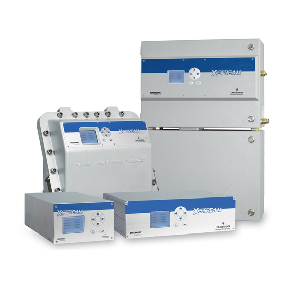
- Page 1 Short Form Manual HASXEE-SFM-HS 05/2017 Gas Analyzers X-STREAM Enhanced Series Short Form Manual www.EmersonProcess.com...
- Page 2 • Read all instructions prior to installing, operating, and servicing the product. • If you do not understand any of the instructions, contact your Emerson Process Management (Rosemount Analytical) representative for clarification. • Follow all warnings, cautions, and instructions marked on and supplied with the product.
-
Page 3: Table Of Contents
2.7.1 Electrical Shielding of Cables ......... . .2-24 Emerson Process Management GmbH & Co. OHG... - Page 4 A.2.2 Field Housings............A-18 TOC-2 Emerson Process Management GmbH & Co. OHG...
- Page 5 Web Browser Measurements Screen ........3-29 Emerson Process Management GmbH & Co. OHG...
- Page 6 Tab. 3-1: Analog Output Signals ..........3-20 Tab. 3-2: Analog Output Signals Settings and Operational Modes ....3-22 TOC-4 Emerson Process Management GmbH & Co. OHG...
-
Page 7: Introduction
HIGHLIGHTS AN OPERATION OR MAINTENANCE PROCEDURE, PRACTICE, CONDITION, STATEMENT, ETC. If not strictly observed, could result in damage to or destruction of equipment, or loss of effectiveness. NOTE! Highlights an essential operating procedure, condition or statement. Emerson Process Management GmbH & Co. OHG... -
Page 8: Terms Used In This Instruction Manual
(gas) to burn. NAMUR NAMUR is an international user association of automation technology in process industries. This organisation has issued experience re- ports and working documents, called recom- mendations (NE) and worksheets (NA). Emerson Process Management GmbH & Co. OHG... -
Page 9: Symbols Used On And Inside The Equipment
Nevertheless several surfaces may remain hot for a limited time. more detailled information available: see in- struction manual before proceeding! more detailled information available: see in- struction manual before proceeding! Emerson Process Management GmbH & Co. OHG... -
Page 10: Symbols Used In This Manual
This symbol may also indicate information import- ant for achieving accurate measurements. Emerson Process Management GmbH & Co. OHG... -
Page 11: Safety Instructions
The following additional instruction manuals are available or referenced within this manual: HASXEE-IM-HS X-STREAM Enhanced Series instruction manual HASICx-IM-H Infallible containment instruction manual Contact your local service center or sales office when missing documents. SAVE ALL INSTRUCTIONS FOR FUTURE USE! Emerson Process Management GmbH & Co. OHG... -
Page 12: Authorized Personnel
• At the end of lifetime, the instrument must be disposed in compliance with the wast regulations. The disposal specialist then has to disassemble the instrument and dispose the battery in compliance with the regulations. Emerson Process Management GmbH & Co. OHG... -
Page 13: Installing And Connecting This Analyzer
Connectors may also be energised. The unit should therefore be disconnected from the power supply before any kind of maintenance, repair or calibration work requiring access to the inside of the unit. Emerson Process Management GmbH & Co. OHG... - Page 14 Connect the exhaust pipe to a suitable flue and inspect the pipes regularly for leaks. All connections must be airtight to avoid leaks; X-STREAM Enhanced series instruction manual on how performing a leak test. Emerson Process Management GmbH & Co. OHG...
- Page 15 NOT apply gas nor operate the internal pump before the warmup time has elapsed! Violation may result in condensation inside the gas paths or damaged pump diaphragm! HIGH TEMPERATURES Hot parts may be exposed when working on photometers and/or heated components in the unit. Emerson Process Management GmbH & Co. OHG...
- Page 16 RECOMMEND implementing one or more additional safety measures: • purging the unit with inert gas • stainless steel internal pipes • flame arrestors on gas inlets and outlets • infallible measuring cells. S-10 Emerson Process Management GmbH & Co. OHG...
- Page 17 If this is not possible, cables must be laid in such a way as to guarantee a clearance of at least 5 mm from power cables. This clearance must be permanently secured (e.g. with cable ties). Emerson Process Management GmbH & Co. OHG S-11...
- Page 18 (CE compliance pursuant to EMC guidelines). In this case the customer or operating company functions as a system builder and must therefore ensure and declare compliance with EMC guidelines. S-12 Emerson Process Management GmbH & Co. OHG...
-
Page 19: Chapter 1 Technical Description
(hazardous areas) without additional safety features. This instruction manual does NOT describe the special conditions necessary to operate gas analyzers in hazardous areas. Please refer to the separate instruction manual, supplied with units for use in hazardous areas. Emerson Process Management GmbH & Co. OHG... -
Page 20: Overview
By default any analyzer is configured with English and Ger- man language sets, while a third can option- ally be added. Currently available: French, Italian, Portuguese and Spanish. Emerson Process Management GmbH & Co. OHG... -
Page 21: Interfaces
• additional relay outputs • digital inputs • Modbus Ethernet • Modbus serial Depending on the unit configuration, the in- terfaces are accessible via either SubminD connectors or screw terminals. Emerson Process Management GmbH & Co. OHG... -
Page 22: Comparison Of The Various X-Stream Analyzer Model
Size (DxHxW): max. ca. 411x133x482 mm Weight: ca. 8–12 kg (17.6 - 26.5 lb) Weight: ca. 11 - 16 kg (24.3 - 35.3 lb) : Limitations apply to selected measurement principles and ranges, Measurement specifications! Emerson Process Management GmbH & Co. OHG... - Page 23 Weight: max. ca. 25 (45) kg / 55.1 (99.2) lb Weight: max. ca. 63 kg (138.9 lb) This model is not covered by this manual! See the separate X-STREAM Ex d manual for hazardous area applications! Emerson Process Management GmbH & Co. OHG...
-
Page 24: X-Stream Xegk: ½ 19 Inch Table-Top Unit
Any free tube fittings can be used for purging the device to minimize interference from the ambi- ent atmosphere, or when measuring corrosive and/or flammable gases. Emerson Process Management GmbH & Co. OHG... -
Page 25: Fig. 1-2: X-Stream Xegk
Gas fittings and valve block AC power input with switch and fuses home Standard gas in- and outlets enter 4 keys for adjustment and menu selection Carrying handle Signal connectors (some optional) Fig. 1-2: X-STREAM XEGK Emerson Process Management GmbH & Co. OHG... -
Page 26: X-Stream Xegp: 19 Inch Table-Top Or Rackmount Design
8 threaded connectors mounted on the rear panel. The configuration of the connectors is indicated on an adhesive label located near the connectors. Emerson Process Management GmbH & Co. OHG... -
Page 27: Fig. 1-3: X-Stream Xegp - Details
Space for additional fittings Signal input/output connectors (some optional) Optional purge gas inlet Cover for eO or tO sensor Strain-reliefs, top view details Screw-type terminal adapters Strain-reliefs Fig. 1-3: X-STREAM XEGP - Details Emerson Process Management GmbH & Co. OHG... -
Page 28: X-Stream Xexf: Field Housing With Single (Xef) Or Dual (Xdf) Compartment
Mains power is supplied via screw-type termi- nals with integrated fuse holders at the right side of the housing, near the front. The wide range power supply unit mounted internally enables the analyzers to be used worldwide. 1-10 Emerson Process Management GmbH & Co. OHG... -
Page 29: Fig. 1-4: X-Stream Xef / Xdf- Front Views
Take care to use anchors and bolts specified to be used for the weight of the units! Take care the wall or stand the unit is intended to be installed at is solid and stable to support the weight! Emerson Process Management GmbH & Co. OHG 1-11... -
Page 30: Fig. 1-5: X-Stream Xef - Side And Bottom View
Cable glands Power supply terminals with integrated fuses Ethernet Service Port and USB connection Ethernet network conncetion (shown with front panel removed) Fig. 1-6: X-STREAM XEF - Power Supply and Signal Terminals 1-12 Emerson Process Management GmbH & Co. OHG... -
Page 31: Xexf Field Housings For Installation In Hazardous Areas (Ex-Zones)
European Ex-zone 2 for measuring non-flam- mable gases. No further measures, such as a supply of protective gas, are necessary. Please contact your local EMERSON Process Management office if you require analyzers for use in hazardous areas. Emerson Process Management GmbH & Co. OHG 1-13... -
Page 32: Measurement Specifications
In total, more than 60 gases are detectable, so the following table gives an overview only. Consult with Emerson for gases / configurations not listed. Not all data is applicable to all analyzer variations. The sample gas(es) and measuring ranges for your specific analyzer are given by the order acknowledgement and on the analyzer's name plate label. -
Page 33: Tab. 1-2: Ir, Uv, Vis, Tcd - Standard And Enhanced Measurement Performance
If installed in series to another measurement system, e. g. IR channel Special conditions apply to model XEFD Note! Do not calibrate, see special calibration notes in the measurement description! Tab. 1-3: Trace Moisture - Standard Measurement Performance Specifications Emerson Process Management GmbH & Co. OHG 1-15... -
Page 34: Tab. 1-4: Oxygen - Standard And Enhanced Measurement Performance Specifications
Related to full scale Note! These sensors require oxygen and moisture to work properly within given specifications! Take care of the separate documentation accompanying the sensors! Tab. 1-5: H S - Standard Measurement Performance Specifications 1-16 Emerson Process Management GmbH & Co. OHG... - Page 35 A remedy for this issue is to purge the housing with gas not containing the component of interest. Emerson Process Management GmbH & Co. OHG 1-17...
-
Page 36: Tab. 1-7: Special Performance Specifications For Gas Purity Measurements
All performance data are verified during the manufacturing process for each unit by the following tests: • Linearization and sensitivity test • Long term drift stability test • Climate chamber test • Cross interference test (if applicable) 1-18 Emerson Process Management GmbH & Co. OHG... -
Page 37: Chapter 2 Installation
USB stick (if applicable) supply with DC • infallible containment instruction man- incl. instructions power cable ual (if applicable to your instrument) (XEGK, option) Fig. 2-1: X-STREAM XE Analyzers - Scope of Supply Emerson Process Management GmbH & Co. OHG... -
Page 38: Introduction
The customer must ensure that the shielding formity when this is legally required (e.g. is correctly connected to the signal cable plug European EMC guidelines). housing. Submin-d plugs and sockets must be screwed to the analyzer. Emerson Process Management GmbH & Co. OHG... -
Page 39: Technical Data
Electrical safety CSA-C/US, based on CAN/CSA-C22.2 No. CAN / USA 61010-1-04 / UL 61010-1, 2nd edition CE, based on EN 61010-1 Europe Electromagnetic compatibility Europe CE, based on EN 61326 Australia C-Tick others NAMUR Emerson Process Management GmbH & Co. OHG... -
Page 40: Specific Technical Data
AC 230 V AC 230 V AC 230 V AC 230 V Power input fuses T 3.15 A T 4 A T 4 A T 6.3 A 5x20 mm 5x20 mm 5x20 mm 5x20 mm Emerson Process Management GmbH & Co. OHG... -
Page 41: Gas Conditioning
EXPLOSION HAZARD Do not supply gases harmful to explosion protection safety components like flame arrestors, cable glands or analyzer enclosure! Violation may result in explosion! Emerson Process Management GmbH & Co. OHG... - Page 42 Measure- analyzer components, if due to ment Specifications“ within this manual. a leak released into the analyzer Perform a calibration each time enclosure! the source of this gas (e. g. bottle) has changed! Emerson Process Management GmbH & Co. OHG...
-
Page 43: Gas Connections
The sensor must be installed before analyzer startup, according the instructions shipped with the sensor! Do not use plastic tubing for trace oxygen measurements as it can permeate oxygen from the ambient air and cause higher than expected oxygen readings. Emerson Process Management GmbH & Co. OHG... -
Page 44: Fig. 2-3: Installation In Bypass Mode
Exhaust Analyzer Exhaust Pressure control valve Flow sensor Filter Sample gas pump Fig. 2-3: Installation in Bypass Mode Emerson Process Management GmbH & Co. OHG... -
Page 45: Electrical Connections
Any break in the earth wire inside or outside the unit may cause exposure to the risk of electrocution and is therefore prohibited. Emerson Process Management GmbH & Co. OHG... - Page 46 The sensor must be installed before analyzer startup, according the instructions shipped with the sensor! Installation instructions: X-STREAM XEGK & XEGP page 2-11 X-STREAM XEXF field housings page 2-16 Notes for wiring signal inputs and outputs page 2-24 2-10 Emerson Process Management GmbH & Co. OHG...
-
Page 47: X-Stream Xegk, X-Stream Xegp
Support the instrument, when installed into a rack! Disregarding may cause per- sonal injury and damaged equipment. Alternative DC Power inlet and separate fuse Fig. 2-4: X-STREAM XEGK - Rear Panel Emerson Process Management GmbH & Co. OHG 2-11... -
Page 48: Fig. 2-5: X-Stream Xegp - Rear View
…, In4, Out4 or 1, 2, … 7, 8) .This avoids confusion in case the analyzer ever has to be discon- nected. XEGK XEGP Gas connections max number max for purging (incl. / separate) 2 incl. 1 incl. & 1 separate material PVDF; stainless steel (opt.) sizes 6/4 mm; ⁄ " 2-12 Emerson Process Management GmbH & Co. OHG... -
Page 49: Fig. 2-6: X-Stream Xegp - Dimensions
Support the instrument, when rack mounting! Disregarding may cause per- sonal injury and damaged equipment. Strain relief bracket, detail (model with clamping adapters) Fig. 2-6: X-STREAM XEGP - Dimensions Emerson Process Management GmbH & Co. OHG 2-13... - Page 50 Note! Configuration of relay contacts as per standard factory setting (NAMUR status signals). NAMUR status signals are automatically configured Fail Safe! Fig. 2-7: Socket X1 - Analog Outputs & Digital Outputs 1-4 2-14 Emerson Process Management GmbH & Co. OHG...
-
Page 51: Fig. 2-8: Power Supply Connectors
Note the configuration of the connector´s pins. Details of any PSUs supplied with the unit are given by the X-STREAM Enhanced Series instruction manual. DC connector XEGK Fig. 2-8: Power Supply Connectors Emerson Process Management GmbH & Co. OHG 2-15... -
Page 52: X-Stream Xexf
Take care to use anchors and bolts specified to be used for the weight of the instruments! Assure that the wall / device for installation is sufficiently attached and stable to carry the instrument! 2-16 Emerson Process Management GmbH & Co. OHG... -
Page 53: Fig. 2-10: X-Stream Xdf - Dimensions For Installation
Gas fittings Connector for potential equalization Cable glands All dimensions in mm [inches in brackets] Fig. 2-10: X-STREAM XDF - Dimensions for Installation Emerson Process Management GmbH & Co. OHG 2-17... -
Page 54: Fig. 2-11: X-Stream Xexf Field Housings - Arrangement Of Terminals, Cable Glands And
8 Ethernet Service Port and USB connection (optional) 4 Glands for power cable 9 Ethernet network connection 5 Glands for signal cables Fig. 2-11: X-STREAM XEXF Field Housings - Arrangement of Terminals, Cable Glands and Gas Connectors 2-18 Emerson Process Management GmbH & Co. OHG... - Page 55 Feed cable through dome nut and clamp- ing insert. Fold braided shield over clamping insert. Make sure that braid- ed shield overlaps the O-ring by 2 mm ( ⁄ “). Emerson Process Management GmbH & Co. OHG 2-19...
- Page 56 Characteristics of terminals: 0.14…1.5 mm (AWG 26…AWG 16), Accepted wire gauge: end sleeves not required Skinning length: 5 mm (0.2") Thread: Min. tightening torque: 0.25 Nm (2.21 in.lb) 2-20 Emerson Process Management GmbH & Co. OHG...
-
Page 57: Fig. 2-12: Terminal Block X1 - Analog Signals And Relay Outputs 1-4 (Xsta)
(NAMUR status signals). NAMUR status signals are automatically configured Fail Safe! Serial Interface Relay Outputs Analog Outputs Fig. 2-12: Terminal Block X1 - Analog Signals and Relay Outputs 1-4 (XSTA) Emerson Process Management GmbH & Co. OHG 2-21... -
Page 58: Fig. 2-13: Power Supply Connections
Finally, tighten the outer dome nut to secure the power cable. Power supply Live L cable gland Neutral N Earth PE Fig. 2-13: Power Supply Connections 2-22 Emerson Process Management GmbH & Co. OHG... - Page 59 Ensure the earthing conductor (protective earth; PE) is connected! When all connections are correctly made and checked, • close the front panel and secure with the fasteners. Emerson Process Management GmbH & Co. OHG 2-23...
-
Page 60: Notes On Wiring Signal Inputs And Outputs
TN-C or TN-C-S systems are described to prevent interference currents between con- here. Fitters familiar with EMC problems must nected enclosures. decide which method should be applied. Fig. 2-15: Shielded Signal Cable, Shielding Connected At One end. 2-24 Emerson Process Management GmbH & Co. OHG... -
Page 61: Fig. 2-16: Signal Cable With Double Shielding, Shieldings Connected At Alternate Ends
Ø 1.5 - 6.5 mm: part # ETC02019 described in seciton 2.6. Ø 5 - 11 mm: part # ETC02020 Ø 10 - 17 mm: part # ETC02021 Ø 16 - 24 mm: part # ETC02022 Emerson Process Management GmbH & Co. OHG 2-25... -
Page 62: Wiring Inductive Loads
(Fig. 2-18). Last Compatible filter components for standard valves are available on request. External relay Analyzer output Fig. 2-19: Driving High-Current Loads Fig. 2-18: Suppressor Diode for Inductive Loads. 2-26 Emerson Process Management GmbH & Co. OHG... -
Page 63: Driving Multiple Loads
(Fig. 2-21). Interference is further re- Lay cables to the loads duced if a twisted multi-core cable is together as far as possible (using twisted-pair cables used. if possible) Fig. 2-21: Loads in Parallel Emerson Process Management GmbH & Co. OHG 2-27... - Page 64 Short Form Manual X-STREAM XE HASXEE-SFM-HS 05/2017 2-28 Emerson Process Management GmbH & Co. OHG...
-
Page 65: Chapter 3 Startup
When operating an instrument at temperatures below 0 °C (32 °F), do NOT apply gas nor operate the internal pump before the warmup time has elapsed! Violation may result in condensation inside the gas paths or damaged pump diaphragm! Emerson Process Management GmbH & Co. OHG... -
Page 66: Performing A Leak Test
(500 hPa)! must not change over a time period of Multi channel instruments: approx. 5 minutes! Analyzers with parallel tubing require separate leak tests for each gas path ! Emerson Process Management GmbH & Co. OHG... -
Page 67: Symbols And Typographical Conventions
(here: key) enter enter Access levels: Access level 1 (user) Access level 2 (expert) Access level 3 (administrator) Access level 4 (service level) Screen shot (here: MAIN MENU) Control.. Setup.. Status.. Info.. Service.. Emerson Process Management GmbH & Co. OHG... -
Page 68: Front Panel Elements
Clear text messages appear in the bottom During an active webserver session, the line, replaced by current analyzer date & heart symbol is replaced by a network sym- time if no messages are to be displayed. bol: Emerson Process Management GmbH & Co. OHG... -
Page 69: Keys
Editing Abort entry keys: down Mode Function Measuring Enter main menu Highlight next menu line Open the previous/next page, Browsing when currently a line beginning with / is highlighted Editing Change current parameter Emerson Process Management GmbH & Co. OHG... - Page 70 Measuring Enter main menu or open 2 measurement display page (if configured) Browsing Open submenu (..) Go to next menu page, when shows in last menu line Editing Move cursor 1 char to the right Emerson Process Management GmbH & Co. OHG...
-
Page 71: Software
The optional unit can only be changed utilizing a setup menu. Variables shown without a co- lon cannot be edited, they are for information only. Emerson Process Management GmbH & Co. OHG... - Page 72 Node30: sor is located. To show the previous page (indicator • place the cursor in the first accessible line and press • press , irrespective of where the cursor left is located. Emerson Process Management GmbH & Co. OHG...
- Page 73 This menu does not show on single-channel units. Within menu descriptions, the following points out, that for multi-channel instruments a selec- tion is required: Multi-channel unit: In SELECT COMPONENT select the chan- nel to be ... Emerson Process Management GmbH & Co. OHG...
-
Page 74: Access Levels & Codes
Access code Status • to select a different digit, left right 00000001 • to submit the code 00000002 enter 00000003 • to exit the edit mode and return to home the previous display. 3-10 Emerson Process Management GmbH & Co. OHG... -
Page 75: Special Messages
Line 4: measured value of channel 4 Function Executing Note! If less than four channels are installed in the Press to return unit, only the measureands for these channels are available for selection. Emerson Process Management GmbH & Co. OHG 3-11... -
Page 76: Measurement Display
There are also functions, that do activate a 2 lines display with additional sec- relay, but are not shown on the display. In ondary parameter line such cases, check the STATUS menu for more information. MEASUREMENT DISPLAY 3-12 Emerson Process Management GmbH & Co. OHG... -
Page 77: Language Settings
• sets this language and the display is enter updated accordingly. • If the selected language is not the intended, repeate the last three steps until the in- tended language is set. Emerson Process Management GmbH & Co. OHG 3-13... -
Page 78: Checking The Settings
Display entering a code. Contrast.. Language: English Phrase Version 1_6_0 Set the preferred language for the software. Measurements.. Measurement Display.. Menu Access.. Auto Home: 10 Min 3-14 Emerson Process Management GmbH & Co. OHG... -
Page 79: Installed Options
(channel) to enter the second menu page. Licenses „Licenses..“ opens another menu where you Key 1: can check or enter license codes to unlock Key 2: optional software features. Key 3: Package None Trial Days Emerson Process Management GmbH & Co. OHG 3-15... -
Page 80: Configuring The Display
Line 4: (Ch1 ... Ch4) are used. Line 5: Note! Notice the headlines of the menus showing a "1": This indicates that you can setup more than 1 measurement display page. 3-16 Emerson Process Management GmbH & Co. OHG... -
Page 81: Calibration Setup
(e.g. span gas calibration using zero gas), which would result in an incorrectly config- ured unit. Emerson Process Management GmbH & Co. OHG 3-17... - Page 82 If no pressure sensor is installed, enter the current ambient pressure here and adjust it, when significant changes take place: this improves the accuracy of the instrument. Pressure compensation Manual Pressure: 1013 hPa Pressure 1013 hPa Pressure Status Good 3-18 Emerson Process Management GmbH & Co. OHG...
-
Page 83: Setting The Analog Outputs
The following options Low Scale: 0.00 High Scale: 100.00 (partly dependent on the number of mea- AutoScale: suring channels and sensors installed) are FailMode: Live available: 0/4 mA: 0.00 20 mA: 100.00 Hold: Emerson Process Management GmbH & Co. OHG 3-19... -
Page 84: Tab. 3-1: Analog Output Signals
[channel] independent (Calc C is the result sensor assigned to the given component of calculator C). (Press2 is the pressure value of the sensor assigned to component 2). Tab. 3-1: Analog Output Signals 3-20 Emerson Process Management GmbH & Co. OHG... - Page 85 Factory setting is "Outrange:" 4-20 mA and Note! "FailMode:" LOW - 10%, unless ordered The related outputs signals can be finetuned otherwise. on a second menu page, if "FailMode" is set to other than Track ( next section). Emerson Process Management GmbH & Co. OHG 3-21...
-
Page 86: Tab. 3-2: Analog Output Signals Settings And Operational Modes
The application of values marked * or ** depends on the setting of "Cut Mode" (for more information Chapter 6 of the X-STREAM Enhanced Series instruction manual). Tab. 3-2: Analog Output Signals Settings and Operational Modes 3-22 Emerson Process Management GmbH & Co. OHG... - Page 87 Note! This behaviour may be undesireable if e.g. the unit is connected to a data acquisition system. Emerson Process Management GmbH & Co. OHG 3-23...
-
Page 88: Setting Concentration Alarms
Note! A hysteresis avoids oscillating alarms in HiHi and LoLo designate pre-alarms, case the concentration is fluctuating around Hi and Lo designate main alarms. a threshold. Fig. 3-3: Arrangement of Concentration Thresholds 3-24 Emerson Process Management GmbH & Co. OHG... -
Page 89: Backup The Settings
• make a local backup to a protected memory Local Backup.. Factory Defaults.. area USB Backup.. • restore the factory default settings, or • make a backup to an external USB device. USB Firmware Update.. Emerson Process Management GmbH & Co. OHG 3-25... - Page 90 Enhanced Series instruction manual for a ensure proper measuring results. comprehensive description of calibration procedures. Chapter 4 for information on how to perform a manual calibration. If your instru- 3-26 Emerson Process Management GmbH & Co. OHG...
-
Page 91: Web Browser
Time 10/01/10 14:00 Connect your computer to the network, open a web browser and enter the instrument´s IP address. If everything is configured properly, the analyzer's logon screen shows up ( 3-32). Emerson Process Management GmbH & Co. OHG 3-27... -
Page 92: Connection To Single Computer
• Click "Close" in "LAN connection properties". On your computer open a web browser and enter the instrument´s IP address. If every- thing is configured properly, the analyzer's logon screen shows up ( next page ). 3-28 Emerson Process Management GmbH & Co. OHG... -
Page 93: Fig. 3-5: Web Browser Logon Screen
Click on the left most icon (question mark) in the status bar, to receive comprehensive on- line help on the X-STREAM XE web browser interface. Fig. 3-6: Web Browser Measurements Screen Emerson Process Management GmbH & Co. OHG 3-29... - Page 94 Short Form Manual X-STREAM XE HASXEE-SFM-HS 05/2017 3-30 Emerson Process Management GmbH & Co. OHG...
-
Page 95: Chapter 4 Maintenance
If the oxygen concentration is known, ambi- est is specified as set point and during zero ent air may be used for an oxygen channel calibration, the actual value is assigned this span calibration. concentration. Emerson Process Management GmbH & Co. OHG... - Page 96 (recommended: approx. 1 l/min and maximum pressure 1500 hPa), and utilizing the correct gas fitting. Ensure the warm-up time after switching on has elapsed! Warm-up time depends on installed measuring system and configuration, mea- surement specifications in section 1.6! Emerson Process Management GmbH & Co. OHG...
-
Page 97: Preparing Calibrations
AfterCalCheck: aborted.This prevents calibration from being performed when the incorrect gas is supplied (e.g. span gas calibration using zero gas), which would result in an incorrectly config- ured unit. Emerson Process Management GmbH & Co. OHG... - Page 98 Proper values for atmospheric pressure are Pressure compensation required for pressure compensation of mea- surement values! Manual Pressure: 1013 hPa With manual entry, update this value regularly Pressure 1013 hPa to achieve proper measurements. Pressure Status Good Emerson Process Management GmbH & Co. OHG...
-
Page 99: Manual Zero Calibration
( sect. 3.4). Ensure the warm-up time after switching on has elapsed! Warm-up time is 15 to 50 minutes depending on installed measu- ring system and configuration! Emerson Process Management GmbH & Co. OHG... - Page 100 SELECT COMPONENT (multi channel ana- lyzer only), to perform a zero calibration for another channel, to CONTROL, where you may start a span calibration. The procedure and screens look similiar to those of a zero calibration: Emerson Process Management GmbH & Co. OHG...
-
Page 101: Manual Span Calibration
SELECT COMPONENT (multi channel Flow 0.00 l/min Status.. analyzer only), to perform a span calibration Results.. for another channel, Restore! press to return to the MEASUREMENT home SCREEN, to finish with manual calibration procedures. Emerson Process Management GmbH & Co. OHG... -
Page 102: Chapter 5 Dismounting And Disposal
Field housings, intended for outside and wall mounted use, weigh between 26 kg (57 lb) and 63 kg (139 lb), depending on version and options installed. Two people and/or lifting equipment is required to lift and carry these units. Emerson Process Management GmbH & Co. OHG... - Page 103 Declaration of Decontamination to a waste disposal contractor. This contractor then has to disassemble the instrument, recycle and also dispose of the contained battery in compliance with all applicable waste treatment regulations. Emerson Process Management GmbH & Co. OHG...
-
Page 104: Appendix
Short Form Manual X-STREAM XE HASXEE-SFM-HS 05/2017 Appendix The contents of this chapter Block diagram page A-2 Assignment of Terminals and Sockets page A-17 Emerson Process Management GmbH & Co. OHG... - Page 105 Short Form Manual X-STREAM XE HASXEE-SFM-HS 05/2017 A.1 Block Diagram A.1 Block Diagram Emerson Process Management GmbH & Co. OHG...
- Page 106 Short Form Manual X-STREAM XE HASXEE-SFM-HS 05/2017 A.1 Block Diagram Emerson Process Management GmbH & Co. OHG...
- Page 107 Short Form Manual X-STREAM XE HASXEE-SFM-HS 05/2017 A.1 Block Diagram Emerson Process Management GmbH & Co. OHG...
- Page 108 Short Form Manual X-STREAM XE HASXEE-SFM-HS 05/2017 A.1 Block Diagram Emerson Process Management GmbH & Co. OHG...
- Page 109 Short Form Manual X-STREAM XE HASXEE-SFM-HS 05/2017 A.1 Block Diagram Emerson Process Management GmbH & Co. OHG...
- Page 110 Short Form Manual X-STREAM XE HASXEE-SFM-HS 05/2017 A.1 Block Diagram Emerson Process Management GmbH & Co. OHG...
- Page 111 Short Form Manual X-STREAM XE HASXEE-SFM-HS 05/2017 A.1 Block Diagram Emerson Process Management GmbH & Co. OHG...
- Page 112 Short Form Manual X-STREAM XE HASXEE-SFM-HS 05/2017 A.1 Block Diagram Emerson Process Management GmbH & Co. OHG...
- Page 113 Short Form Manual X-STREAM XE HASXEE-SFM-HS 05/2017 A.1 Block Diagram A-10 Emerson Process Management GmbH & Co. OHG...
- Page 114 Short Form Manual X-STREAM XE HASXEE-SFM-HS 05/2017 A.1 Block Diagram Emerson Process Management GmbH & Co. OHG A-11...
- Page 115 Short Form Manual X-STREAM XE HASXEE-SFM-HS 05/2017 A.1 Block Diagram A-12 Emerson Process Management GmbH & Co. OHG...
- Page 116 Short Form Manual X-STREAM XE HASXEE-SFM-HS 05/2017 A.1 Block Diagram Emerson Process Management GmbH & Co. OHG A-13...
- Page 117 Short Form Manual X-STREAM XE HASXEE-SFM-HS 05/2017 A.1 Block Diagram A-14 Emerson Process Management GmbH & Co. OHG...
- Page 118 Short Form Manual X-STREAM XE HASXEE-SFM-HS 05/2017 A.1 Block Diagram Emerson Process Management GmbH & Co. OHG A-15...
- Page 119 Short Form Manual X-STREAM XE HASXEE-SFM-HS 05/2017 A.1 Block Diagram A-16 Emerson Process Management GmbH & Co. OHG...
-
Page 120: Tabletop & Rack Mount Analyzers
Socket X4 - Digital I/O Connector X5 - Analog inputs Ethernet connector (Assignment of screw terminals adaptor: see XSTD on next page) (Assignment of screw terminals adaptor: see XSTI on next page) for Modbus Emerson Process Management GmbH & Co. OHG A-17... -
Page 121: Field Housings
Power cord P4.12 D0(-) TXD0(-) not used not used entry Service Port Connector - Ethernet connector Power terminals Signal Terminals Strips Serial RS 232 interface for Modbus A-18 Emerson Process Management GmbH & Co. OHG... - Page 122 Short Form Manual X-STREAM XE HASXEE-SFM-HS 05/2017...
- Page 123 ©2016 Emerson Process Management. All rights reserved. The Emerson logo is a trademark and service mark of Emerson Electric Co. Rosemount Analytical is a mark of one of the Emerson Process Management family of companies. All other marks are the property of their respective owners.
Need help?
Do you have a question about the Rosemount Analytical X-STREAM Enhanced Series and is the answer not in the manual?
Questions and answers