Table of Contents
Advertisement
Quick Links
Download this manual
See also:
User Manual
Advertisement
Table of Contents
Troubleshooting

Related Manuals for Emerson Rosemount TCL


Summary of Contents for Emerson Rosemount TCL
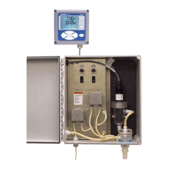
- Page 1 Manual LIQ-MAN-TCL-1056, Rev E July 2017 ™ Rosemount Total Chlorine System with Rosemount 1056 Transmitter...
- Page 2 Essential instructions Read this page before proceeding! Rosemount designs, manufactures, and tests its products to meet many national and international standards. Because these instruments are sophisticated technical products, you must properly install, use, and maintain them to ensure they continue to operate within their normal specifications.
- Page 3 Date Notes 07/07 This is the initial release of the product manual. This manual has been reformatted to reflect the Emerson documentation style and updated to reflect any change in the prod- uct offering. 11/07 Page 3 additions to Section 1.2, page 5 changes to the Analyzer (option selection) table,...
-
Page 5: Table Of Contents
Contents Contents Chapter 1 Description and specifications ..................1 Features ............................1 Specifications ..........................2 Ordering information and accessories ..................5 Chapter 2 Principles of operation ....................9 Chapter 3 Installation ........................11 Unpacking and inspection ......................11 Installation ..........................11 3.2.1 General information ....................11 3.2.2 Install the transmitter ....................11 3.2.3... - Page 6 Reagent ........................74 10.3.2 Sample and reagent tubing ..................75 10.3.3 Replacing sample tubing ..................... 76 10.3.4 Peristaltic pump tubing ....................77 10.3.5 Replacing the air pump ....................80 10.3.6 Replacing the air pump diaphragm and check valves ...........82 Rosemount TCL...
- Page 7 Contents Chapter 11 Troubleshooting ......................85 11.1 Overview ........................... 85 11.2 Using the diagnostic feature ...................... 85 11.3 Troubleshooting when a Fault message is showing ..............86 11.3.1 Main Board CPU, Main Board Factory Data, and Main Board User Data errors ....86 11.3.2 Hardware Error ......................
- Page 8 Contents Rosemount TCL...
-
Page 9: Description And Specifications
Description and specifications Description and specifications Features Rosemount TCL Sample Conditioning System The sample conditioning system permits a single sensor to measure total chlorine in water. The sample conditioning system continuously injects a solution of acetic acid (vinegar) and potassium iodide into the sample. The acid lowers the pH to between 3.5 and 4.5 and allows total chlorine in the sample to quantitatively react with the potassium iodide to produce iodine. -
Page 10: Specifications
Inlet pressure <100 psig (791 kPa abs) Flow At least 0.25 gph (15 mL/min) Temperature 0 to 50 °C (32 to122 °F) Total alkalinity <300 mg/L as CaCO . For samples containing <50 mg/L alkalinity, consult the factory. Rosemount TCL... - Page 11 Description and specifications Table 1-1: Sample Conditioning System (continued) Physical characteristics Specifications Sample conditioning system Reagent Potassium iodide in vinegar Reagent usage 5 gallons last approximately 60 days. Reagent pump Fixed speed peristaltic pump, about 0.2 mL/min Sample pump Fixed speed peristaltic pump, about 11 mL/min Table 1-2: Rosemount 1056 Transmitter Physical characteristics...
- Page 12 0 to 50 °C (32 to 122 °F) Electrolyte capacity Approximately 25 mL Electrolyte life Approximately 4 months Weight/shipping weight 1 lb/3 lb (0.5 kg/1.5 kg) (1) Noryl is a registered trademark of General Electric. (2) Viton is a registered trademark of DuPont Performance Elastomers. Rosemount TCL...
-
Page 13: Ordering Information And Accessories
Reagent kits must be ordered separately. Reagent kits for 0-5 ppm and 0-10 ppm chlorine are available. For higher ranges, consult the factory. Table 1-5. Table 1-5: Rosemount TCL Total Chlorine System Ordering Information Model Sensor type Total Chlorine System Power input... - Page 14 Description and specifications Table 1-5: Rosemount TCL Total Chlorine System Ordering Information (continued) Rosemount 1056-03-24-38-DP, alarm relays, Profibus DP Sensor No selection - no sensor Rosemount 499ACL-02-54 Total Chlorine Sensor with standard cable Rosemount 499ACL-02-54-60 Total Chlorine Sensor with optimum EMI/RFI ca-...
- Page 15 Description and specifications Table 1-6: Sample Conditioning System Accessories (continued) Part number Description 24165-01 Acetic acid, 2 x 2.5 gal (9.5 L) bottles/case, with 50 g po- tassium iodide (0-10 ppm total chlorine) Table 1-7: Rosemount 1056 and 56 Transmitters Accessories Part number Description 23554-00...
- Page 16 Description and specifications Rosemount TCL...
-
Page 17: Principles Of Operation
Principles of operation Principles of operation Total chlorine by definition is the iodine produced in a sample when it is treated with potassium iodide at a pH between 3.5 and 4.5. Typically, acetic acid (or vinegar) is used to adjust the pH. The total chlorine system consists of a sample conditioning system, which injects the reagent into the sample, and a sensor and transmitter, which measure the amount of iodine produced. - Page 18 Principles of operation Rosemount TCL...
-
Page 19: Chapter 3 Installation
Installation Installation Unpacking and inspection Complete the following steps when you unpack your instrument. Inspect the shipping containers. If there is damage, contact the shipper immediately for instructions. If there is no apparent damage, unpack the containers. Ensure that all items shown on the packing list are present. If items are missing, notify Rosemount immediately. - Page 20 Installation Type of mounting Figure Wall or pipe Figure 3-2 Figure 3-1: Panel Mounting Dimensions Rosemount TCL...
-
Page 21: Install The Sample Conditioning Enclosure
Installation Figure 3-2: Pipe and Wall Mounting Dimensions (Mounting bracket PN 23820-00) Section 4.1 for more information about the conduit openings. Section 4.2 for wiring instructions. 3.2.3 Install the sample conditioning enclosure Follow the steps below to install the sample conditioning enclosure. Instruction Manual... - Page 22 Installation Refer to Figure 3-3, Figure 3-4, and Figure 3-5 for installation details. Figure 3-3: Installing the Sample Conditioning Enclosure Rosemount TCL...
- Page 23 Installation Figure 3-4: TCL Case Dimensions Figure 3-5: Reagent Tubing Assembly Instruction Manual...
-
Page 24: Install The Sensor
Slip the nut over the end of the sensor. Thread the adapter onto the sensor. Hand-tighten only. If you are using a VP cable, connect the cable to the sensor. The connector and receptacle are keyed to ensure proper mating. Rosemount TCL... - Page 25 Installation Once the key has slid into place, tighten the connection by turning the knurled ring clockwise. Remove the protective cap from the end of the sensor. Insert the sensor in the flow cell. Hand tighten the nut. Instruction Manual...
- Page 26 Installation Rosemount TCL...
-
Page 27: Chapter 4 Wiring
Wiring Wiring Prepare transmitter conduit openings The transmitter enclosure has six conduit openings. Four conduit openings are fitted with conduit plugs. Conduit openings accept 1/2 in. conduit fittings or PG 13.5 cable glands. To keep the case watertight, block unused openings with NEMA 4X or IP65 conduit plugs. Note Use watertight fittings and hubs that comply with the requirements of UL514B. -
Page 28: Make Power, Alarm, Output, And Sensor Connections In The Transmitter
4.3.1 Power Wire AC mains power supply to the power supply board, which is mounted vertically on the left hand side of the transmitter enclosure. The power connector is at the top of the board. Rosemount TCL... -
Page 29: Analog Output Wiring
Wiring Procedure Unplug the connector from the board and wire the power cable to it. Lead connections are marked on the connector. (L is live or hot; N is neutral; the ground connection has the standard symbol.) AC power wiring should be 14 gauge or greater. Run the power wiring through the conduit opening nearest the power terminal. -
Page 30: Alarm Wiring
Keep alarm relay wiring separate from signal wiring. Do not run signal and power or relay wiring in the same conduit or close together in a cable tray. Sensor wiring If it is necessary to replace the sensor cable, refer to the instructions below. Shut off power to the transmitter. Rosemount TCL... - Page 31 Wiring Locate the chlorine signal board. Slot 1 (left) Slot 2 (center) Slot 3 (right) communication input 1 (chlorine) input 2 (optional) Insert the sensor cable through the conduit opening nearest the chlorine board. Slide the board forward to gain access to the wires and terminal screws. Connect the sensor to the chlorine board.
-
Page 32: Apply Power To The Transmitter And Complete Quick Start
The next step is to configure sensor 1. Sensor 1 is the total chlorine sensor. The screen has two control boxes. a. For measurement, choose Total chlorine. b. Choose the desired units, mg/L or ppm. Choose Total Chlorine for sensor 1 (S1). Choose the desired units for chlorine. Rosemount TCL... - Page 33 Wiring Choose the desired temperature units. The main display appears. The outputs and alarms (if an alarm board is present) are assigned to default values. To change outputs, alarms, and other settings, go to the main menu and choose Program. Follow the prompts. A menu tree is on the following page.
- Page 34 Wiring Rosemount TCL...
-
Page 35: Chapter 5 Startup
Startup Startup Complete Chapter 4 before starting this section. Prepare the reagent Complete the following steps to prepare the potassium iodide reagent. WARNING! HAZARDOUS SUBSTANCE The reagent contains potassium iodide dissolved in distilled vinegar or 5% acetic acid. Avoid contact with skin and eyes. Wash thoroughly after using. Important Do not prepare the solution until ready to use. -
Page 36: Zero The Sensor
Adjust the sample flow until a slow stream of liquid is running down the inside tube of the sampling cup. Begin operation and calibrate the sensor Complete the following steps to start operating the Rosemount TCL and calibrate the 499ACL-02 Sensor. Turn on the reagent and sample pump switches. -
Page 37: Display And Operation
Display and operation Display and operation Display The transmitter has a six line display. Figure 6-1. The display can be customized to meet your requirements. Refer to Section 6.6. Figure 6-1: Main Display When the transmitter is being programmed or calibrated, the display changes to a screen similar to the one shown in Figure 6-2. -
Page 38: Keypad
Display and operation Figure 6-3: Arrow Bar The arrow bar shows whether additional items in a list are available. Keypad Local communication with the transmitter is through the membrane keypad. Figure 6-4 Figure 6-5 explain the operation of the keys. Rosemount TCL... - Page 39 Display and operation Figure 6-4: Transmitter Keypad Four navigation keys move the cursor around the screen. The position of the cursor is shown in reverse video. The navigation keys are used to increase or decrease the value of a numeral. Press ENTER to select an item and store numbers and settings.
-
Page 40: Programming The Transmitter - Tutorial
When you have reached the bottom, the arrow will point up. Move the cursor back to Outputs and press ENTER. The Outputs screen appears. The cursor is on Range. Output range is used to assign values to the low and high current outputs. Rosemount TCL... - Page 41 Display and operation Press ENTER. The Output Range screen appears. The screen shows the present values assigned to output 1 (O1) and output 2 (O2). The screen also shows which sensors the outputs are assigned to. S1 is sensor 1, and S2 is sensor 2. S2 appears only if you have a dual input Rosemount 1056 transmitter.
-
Page 42: Security
If the entry is correct, the main Menu screen appears. The user has access to the sub- menus the code entitles him to. If the entry is wrong, the Invalid code screen appears. 6.4.2 Assigning security codes Section 7.7. 6.4.3 Bypassing security codes Call the factory. Rosemount TCL... -
Page 43: Using Hold
Display and operation Using hold 6.5.1 Purpose To prevent unwanted alarms and improper operation of control systems or dosing pumps, place the alarms and outputs assigned to the sensor in hold before removing it for maintenance. During hold, outputs assigned to the sensor remain at the last value, and alarms assigned to the sensor remain in their present state. -
Page 44: Configuring The Main Display
Main Format lets you configure the second line in the main display as well as the four smaller items at the bottom of the display. Move the cursor to the desired place in the screen and press ENTER. Rosemount TCL... - Page 45 Display and operation Scroll through the list of items and select the parameter you wish to be displayed. Once you are done making changes, press EXIT twice to return to the display menu. Press MENU and then EXIT to return to the main display. The following abbreviations are used in the quadrant display.
- Page 46 Display and operation Rosemount TCL...
-
Page 47: Programming The Transmitter
Programming the transmitter Programming the transmitter General This section describes how to make the following program settings using the local keypad. Configure and assign values to the analog current outputs. Configure and assign values to the alarm relays (if the alarm board is installed). Choose the type of chlorine measurement being made. - Page 48 2. Temperature compensation automatic or manual automatic Security code 1. Calibrate/Hold 000 to 999 2. Program/Display 000 to 999 Calibration - Analog Outputs 1. 4mA 0.000 to 22.000 mA 4.000 mA 2. 20 mA 0.000 to 22.000 mA 20.000 mA Rosemount TCL...
-
Page 49: Configuring, Ranging, And Simulating Outputs
Programming the transmitter Configuring, ranging, and simulating outputs 7.3.1 Purpose This section describes how to configure, range, and simulate the two analog current outputs. Important Configure the outputs first. Configuring an output means a. Assigning a sensor and measurement (chlorine or temperature) to an output. b. -
Page 50: Procedure - Configure Outputs
Complete the following steps to configure the analog current outputs. Press MENU. The main Menu screen appears. Move the cursor to Program and press ENTER. The cursor is on Outputs. Press ENTER. Choose Configure. Choose Output 1 or Output 2. Rosemount TCL... -
Page 51: Procedure - Ranging Outputs
Programming the transmitter The screen shows the present configuration. There are six items: Assign (S1 is sensor 1, S2 is sensor 2), Range, Scale, Dampening, Fault Mode, and Fault Value. To display the fifth and sixth items, scroll to the bottom of the screen and continue scrolling. To make a change, move the cursor to the desired line and press ENTER. -
Page 52: Procedure - Simulating Outputs
To return to the main display, press MENU and then EXIT. 7.3.5 Procedure - simulating outputs Complete the following steps to simulate an output by making the transmitter generate an output current equal to the value you enter. Press MENU. Rosemount TCL... - Page 53 Programming the transmitter The main Menu screen appears. Move the cursor to Program and press ENTER. The cursor is on Outputs. Press ENTER. Choose Simulate. Choose Output 1 or Output 2. Enter the desired simulated output current. Instruction Manual...
-
Page 54: Configuring Alarms And Assigning Setpoints
If an alarm was programmed as a fault alarm, the alarm activates. At the same time, a fault message appears in the main display. Alarm logic, Figure 7-1 Figure 7-2. setpoints, and deadbands Rosemount TCL... - Page 55 Programming the transmitter Figure 7-1: High Alarm Logic The alarm activates when the chlorine concentration exceeds the high setpoint. The alarm remains activated until the reading drops below the value determined by the deadband. Figure 7-2: Low Alarm Logic The alarm activates when the chlorine concentration drops below the low setpoint. The alarm remains activated until the reading increases above the value determined by the deadband.
-
Page 56: Procedure - Configuring Alarms And Assigning Setpoints
7.4.3 Procedure - configuring alarms and assigning setpoints Complete the following steps to configure the alarms and assign setpoints. Press MENU. The main Menu screen appears. Move the cursor to Program and press ENTER. Choose Alarms. Rosemount TCL... - Page 57 Programming the transmitter Choose Configure/Setpoint. Choose Alarm 1, Alarm 2, Alarm 3, or Alarm 4. The screens summarizes the present configuration and setpoints. There are nine items: Setpoint, Assign (S1 is sensor 1 and S2 is sensor 2), Logic, Deadband, Interval time, On time, Recover time, and Hold while active.
-
Page 58: Procedure - Simulating Alarms
Complete the following steps to make the transmitter energize or de-energize an alarm relay. Press MENU. The main Menu screen appears. Move the cursor to Program and press ENTER. Choose Alarms. Choose Simulate. Choose Alarm 1, Alarm 2, Alarm 3, or Alarm 4. Rosemount TCL... -
Page 59: Procedure - Synchronizing Timers
Programming the transmitter Choose Don't simulate, De-energize, or Energize. Press MENU or EXIT to end simulation. 7.4.5 Procedure - synchronizing timers Synch Timers is available only if two or more alarm relays have been configured as interval timers. Press MENU. The main Menu screen appears. -
Page 60: Configuring The Measurement
0.XX or 0.XXX. 7.5.3 Procedure - configuring the measurement Complete the following steps to configure the transmitter to measure total chlorine. Press MENU. The main Menu screen appears. Move the cursor to Program and press ENTER. Rosemount TCL... -
Page 61: Configuring Temperature Related Settings
Programming the transmitter Choose Measurement. The screen below appears only if you have a dual input 1056. Choose the chlorine sensor. The screen summarizes the present configuration for the chlorine sensor. There are four items: Measure, Units, Filter, and Resolution. To make a change, move the cursor to the desired line and press ENTER. -
Page 62: Definitions - Chlorine
Choose Temperature. The screen summarizes the present sensor configuration. There are between two and five items. Units and S1 Temp Comp always appear. If manual temperature compensation was selected, the manual temperature value also appears. If you have Rosemount TCL... -
Page 63: Configuring Security Settings
Programming the transmitter a dual input transmitter, temperature compensation items appear for the other sensor. Only four items are shown at a time. To view the remaining items, scroll to the bottom of the screen and continue scrolling. To make a change, move the cursor to the desired line and press ENTER. A screen appears in which the present setting can be edited. -
Page 64: Procedure - Configuring Security Settings
The security code takes effect two minutes after pressing ENTER. To return to the main display, press MENU and then EXIT. Resetting the transmitter 7.8.1 Purpose This section describes how to clear user-entered values and restore default settings. There are three resets: Rosemount TCL... -
Page 65: Procedure - Resetting The Transmitter
Programming the transmitter Resetting to factory default clears ALL user-entered settings, including sensor and analog output calibration, and returns ALL settings and calibration values to the factory defaults. Resetting a sensor calibration to the default value clears user-entered calibration data for the selected sensor but leaves all other user-entered data unaffected. Resetting the analog output calibration clears only the user-entered analog output calibration. - Page 66 Programming the transmitter Rosemount TCL...
-
Page 67: Chapter 8 Digital Communications
Digital communications Digital communications For information about digital communications, refer to the following manuals. HART 51-1056HT Model 56 HART Addendum Profibus DP 51-1056DP Model 56 Profibus DP Addendum Instruction Manual... - Page 68 Digital communications Rosemount TCL...
-
Page 69: Chapter 9 Calibration
Calibration Calibration Introduction The Calibrate menu allows you to do the following: Calibrate the temperature sensing element in the total chlorine sensor. Calibrate the chlorine sensor. Calibrate the analog outputs. Calibrating temperature 9.2.1 Purpose The total chlorine sensor is a membrane-covered amperometric sensor. As the sensor operates, iodine, produced by the reaction between total chlorine and the vinegar/ potassium iodide agent, diffuses through the membrane and is consumed at an electrode immediately behind the membrane. - Page 70 If the present temperature is more than 5 °C different from the value entered, an error message appears. To force the transmitter to accept the calibration, choose Yes. To repeat the calibration, choose No. For troubleshooting assistance, see Section 11.5. To return to the main display, press MENU and then EXIT. Rosemount TCL...
-
Page 71: Calibrating Total Chlorine
Figure 9-1. First, the sample flows into a conditioning system (the Rosemount TCL) where it is treated with acetic acid (vinegar) and potassium iodide. The acid lowers the pH, which allows total chlorine in the sample to quantitatively oxidize the iodide to iodine. The treated sample then flows to the sensor. - Page 72 Take the grab sample from a point as close as close as possible to the inlet of the TCL sample conditioning system. • Total chlorine solutions are unstable. Run the test immediately after taking the sample. Try to calibrate the sensor when the chlorine concentration is at the upper end of the normal operating range. Rosemount TCL...
-
Page 73: Procedure - Zeroing The Sensor
Calibration 9.3.2 Procedure - zeroing the sensor Complete the following steps to calibrate the sensor with the zero standard. Remove the sensor from the flow cell and place it in a beaker of deionized water. Be sure no air bubbles are trapped against the membrane. Observe the sensor current. The current drops rapidly at first and then gradually reaches a stable zero value. - Page 74 To force the transmitter to accept the zero current, choose Yes. To repeat the calibration, choose No. For troubleshooting information, see Section 11.5. If the zero current is much larger than expected, the zero calibration failure screen appears. Rosemount TCL...
-
Page 75: Procedure - Calibrating The Sensor
Calibration The transmitter will not update the zero current. For troubleshooting assistance, see Section 11.5. To return to the main display, press MENU and then EXIT. 9.3.3 Procedure - calibrating the sensor Complete the following steps to calibrate the total chlorine sensor with the full scale standard solution. - Page 76 9, and the display returns to the screen in step 6. If the sensitivity is too far outside the range of expected values the following screen appears. The transmitter doesn't update the calibration. For troubleshooting assistance, see Section 11.5. To return to the main display, press MENU and then EXIT. Rosemount TCL...
-
Page 77: Calibrating Analog Outputs
Calibration Calibrating analog outputs 9.4.1 Purpose Although the transmitter analog outputs are calibrated at the factory, they can be trimmed in the field to match the reading from a standard milliameter. Both the low (0 or 4 mA) and high (20 mA) outputs can be trimmed. 9.4.2 Procedure Complete the following steps to calibrate the transmitter's analog outputs. - Page 78 If the user entered value is more than ±1 mA different from the nominal value, a possible error screen appears. To force the transmitter to accept the calibration, choose Yes. To return to the main display, press MENU and then EXIT. Rosemount TCL...
-
Page 79: Chapter 10 Maintenance
Maintenance Maintenance 10.1 Transmitter The Rosemount 1056 Transmitter used with the TCL requires little maintenance. Clean the transmitter case and front panel by wiping with a clean soft cloth dampened with water only. Do not use solvents, like alcohol, that might cause a buildup of static charge. -
Page 80: Total Chlorine Sensor
Place a drop of electolyte solution on the cathode. Invert the membrane assembly and place it over the cathode stem. Screw the membrane retainer back in place. Hold the sensor with the membrane pointing down. Shake the sensor a few times, as though shaking down a clinical thermometer. Rosemount TCL... -
Page 81: Replacing The Electrolyte Solution And Membrane
Maintenance 10.2.4 Replacing the electrolyte solution and membrane WARNING! HARMFUL SUBSTANCE Fill solution may cause irritation. Avoid contact with skin and eyes. May be harmful if swallowed.. Procedure Unscrew the membrane retainer. Remove the membrane assembly and O-ring. Figure 10-2. Figure 10-2: Sensor Parts Hold the sensor over a container with the cathode pointing down. -
Page 82: Sample Conditioning System
O-ring 23502-02 Total chlorine membrane kit: includes three membrane assemblies and three O-rings. 9210438 Total chlorine sensor fill solution , 4 oz (120 mL) 10.3 Sample conditioning system 10.3.1 Reagent The sample conditioning reagent lasts about two months. Rosemount TCL... -
Page 83: Sample And Reagent Tubing
Maintenance Before putting fresh reagent in the carboy, discard any small amount of remaining reagent. To prepare the reagent refer to the procedure in Section 5.1. See Table 10-2 ordering information. 10.3.2 Sample and reagent tubing Periodically inspect sample and reagent tubing for cracks and leaks. Replace tubing if it is damaged. -
Page 84: Replacing Sample Tubing
Disconnect the other end of the sample pump discharge tubing from the flow cell. Pull the air injection tubing off the air injection tee. Disconnect the sample inlet and drain tubing. Install the replacement sample pump suction and discharge tubing assemblies. Rosemount TCL... -
Page 85: Peristaltic Pump Tubing
Maintenance The assemblies look similar. To tell the difference, note the air injection tee in the discharge tubing assembly has a larger diameter barb than the reagent injection tee in the suction tubing assembly. Install replacement sample inlet and drain tubing. The sample inlet tubing is longer than the drain tubing. - Page 86 Gently stretch the tubing over the rollers and insert the other fitting into the receiving socket on the other side of the pump. Figure 10-8. Figure 10-8: Inserting New Tubing Replace the pump cover. Rosemount TCL...
- Page 87 Maintenance a. Place the cover on the pump casing. Figure 10-9. Figure 10-9: Replacing the Pump Cover b. Be sure the pins at the bottom of the cover (Figure 10-10) ride on the tracks in the pump casing. Figure 10-10: Pins c.
-
Page 88: Replacing The Air Pump
Disconnect the air pump inlet tubing from the barbed tubing in the bottom of the enclosure. Figure 10-12: Replacing the Air Pump Remove the four screws (circled in Figure 10-12 Figure 10-13) holding the air pump access panel. Pull out the pump and panel. Rosemount TCL... - Page 89 Maintenance Figure 10-13: Air Pump Access Panel Disconnect the air inlet and outlet tubing from the air pump. Figure 10-14. Figure 10-14: Air Inlet and Outlet Tubing Remove the five screws (surrounded by squares in Figure 10-13) holding the air pump to the access panel.
-
Page 90: Replacing The Air Pump Diaphragm And Check Valves
Replacing the air pump diaphragm and check valves Complete the following steps to replace the air pump diaphragm and check valves on your total chlorine system. WARNING! HAZARDOUS VOLTAGE Can cause severe injury or death. Disconnect power before servicing. Procedure Disconnect power to the transmitter. Rosemount TCL... - Page 91 Maintenance Refer to Figure 10-12. Disconnect the reagent and air injection tubes. Disconnect the suction and discharge fitting by turning the Luer fitting in the direction shown in the figure. Disconnect the air pump inlet tubing from the barbed fitting at the bottom of the enclosure.
- Page 92 Potassium iodide, 25 g, sufficient for 5 gallons (19 L) of vinegar (for 0 - 5 ppm total chlorine) 24164-01 Potassium iodide, 50 g, sufficient for 5 gallons (19 L) of vinegar (for 0 - 10 ppm total chlorine) Rosemount TCL...
-
Page 93: Chapter 11 Troubleshooting
Troubleshooting Troubleshooting 11.1 Overview The transmitter continuously monitors itself and the sensor(s) for problems. When the transmitter identifies a problem, the word warning or fault appears intermittently in the lower line of the display. When the fault or warning message appears, press DIAG for more information. -
Page 94: Troubleshooting When A Fault Message Is Showing
Board User Data errors These error messages mean the main board is corrupted or the eeprom data on the main board is corrupted. Cycle the power off and then on. If cycling the power does not help, call the factory. Rosemount TCL... -
Page 95: Hardware Error
Troubleshooting The main board must be replaced. To do this, you must return the transmitter to the factory. If cycling the power does not help and the fault message was Main Board User Data, reset the transmitter to factory default, re-enter user settings, and repeat calibration. -
Page 96: Sensor Rtd Open
If the measured resistance is outside the expected range, the transmitter displays the out of range error message. Check wiring connections. Disconnect the sensor from the transmitter and use an ohmeter to check the resistance across the RTD. Rosemount TCL... -
Page 97: Troubleshooting When A Warning Message Is Showing
Troubleshooting Figure 4-4 Figure 4-5. The resistance should be about 110 Ω. If there is an open or short circuit, or if the resistance is more than about 5% different from 110 Ω, the sensor has failed and should be replaced. If there is no open or short, check the transmitter. -
Page 98: Sensor Temperature High Or Low
(zero current is too high). Zero current is unstable. Section 11.5.2 Sensor can be calibrated, but the current is too low. Section 11.5.3 Process readings are erratic or wander. Section 11.5.4 Readings drift. Section 11.5.5 Readings are too high. Section 11.5.6 Rosemount TCL... -
Page 99: Zero Current Is Too High
Troubleshooting Problem See Section Readings are too low. Readings are too low.Section 11.5.3 Current output is too low. Section 11.5.8 Alarm relays do not operate when setpoint is exceeded Section 11.5.9 or do not release when reading is below setpoint. 11.5.1 Zero current is too high. - Page 100 To check reagent flow: a. Turn off the reagent and sample pumps. b. Disconnect the reagent tubing at the injection tee. See B in Figure 11-1. c. Place the end of the tubing in a 5 mL graduated cylinder. Rosemount TCL...
-
Page 101: Process Readings Are Erratic Or Wander
Troubleshooting d. Start the reagent pump and collect reagent for ten minutes. e. Note the volume of reagent collected in the graduated cylinder. After ten minutes, the volume should be about 2 mL. Figure 11-1: Disconnecting sample (A) and reagent (B) tubing prior to checking flow 11.5.4 Process readings are erratic or wander. -
Page 102: Readings Drift
Is the standard temperature sensor submerged to the correct level? 11.5.8 Current output is too low. Load resistance is too high. Maximum load is 600 Ω. 11.5.9 Alarm relays don't work. Verify the relays are properly wired. Verify that deadband is correctly set. See Section 7.4. Rosemount TCL... -
Page 103: Simulating Inputs
Troubleshooting 11.6 Simulating inputs To check the performance of the transmitter, use a decade box and 1.5 V battery to simulate the current from the sensor. The battery, which opposes the polarizing voltage, is necessary to ensure that the sensor current has the correct sign. Disconnect the anode and cathode leads from terminals 8 and 10 on TB1 and connect a decade box and 1.5 V battery as shown in Figure... -
Page 104: Simulating Temperature
The offset is also applied to the simulated resistance. The transmitter is measuring temperature correctly if the difference between measured temperatures equals the difference between the values in the table to within ±0.1 °C. Rosemount TCL... - Page 105 Troubleshooting For example, start with a simulated resistance of 103.9 Ω, which corresponds to 10.0 °C. Assume the offset from the sensor calibration was -0.3 Ω. Because of the offset, the transmitter calculates temperature using 103.6 Ω. The result is 9.2 °C. Now change the resistance to 107.8 Ω, which corresponds to 20.0 °C.
- Page 106 Troubleshooting Rosemount TCL...
-
Page 107: Return Of Material
Return of material Return of material For any repair, warranty, and return of instrument requests, please contact the factory. Instruction Manual... - Page 108 Emerson Automation Solutions The Emerson logo is a trademark and service mark of Emerson 1 Pandan Crescent Electric Co. Rosemount is a mark of one of the Emerson family of Singapore 128461 companies. All other marks are the property of their respective Singapore owners.
Need help?
Do you have a question about the Rosemount TCL and is the answer not in the manual?
Questions and answers