Emerson Rosemount 8800D Series Reference Manual
Vortex flow meter with modbus protoco
Hide thumbs
Also See for Rosemount 8800D Series:
- Reference manual (192 pages) ,
- Quick start manual (56 pages) ,
- Quick installation manual (31 pages)

Related Manuals for Emerson Rosemount 8800D Series


Summary of Contents for Emerson Rosemount 8800D Series
- Page 1 Reference Manual 00809-0400-4004, Rev AB October 2021 ™ Rosemount 8800D Series Vortex Flow Meter with Modbus Protocol...
-
Page 3: Table Of Contents
Reference Manual Contents 00809-0400-4004 October 2021 Contents ™ Rosemount 8800D Vortex Flowmeter................. 0 Chapter 1 Safety messages......................7 Chapter 2 Introduction......................9 2.1 Overview............................. 9 Chapter 3 Pre-installation......................11 3.1 Planning............................ 11 3.2 Commissioning..........................15 Chapter 4 Basic installation...................... 17 4.1 Handling............................17 4.2 Flow direction.......................... - Page 4 Contents Reference Manual October 2021 00809-0400-4004 7.1 LCD display..........................47 7.2 Compensated K-factor.......................47 7.3 Meter body..........................48 7.4 Meter factor..........................48 7.5 Variable mapping........................48 7.6 Pulse output..........................49 7.7 Signal processing........................50 7.8 Special process variable units.....................53 7.9 Flow totalizer..........................54 Chapter 8 Troubleshooting......................
- Page 5 Reference Manual Contents 00809-0400-4004 October 2021 C.7 Example calculations....................... 119 Appendix D Modbus details.......................125 D.1 Byte transmission order......................125 D.2 Input registers (Modbus function code 4)................125 D.3 Holding registers (Modbus function code 3)................128 Reference Manual...
- Page 6 Contents Reference Manual October 2021 00809-0400-4004 ™ Rosemount 8800D Series Vortex Flow Meter with Modbus Protocol...
-
Page 7: Chapter 1 Safety Messages
Reference Manual Safety messages 00809-0400-4004 October 2021 Safety messages WARNING Explosion hazards. Failure to follow these instructions could cause an explosion, resulting in death or serious injury. • Verify the operating atmosphere of the transmitter is consistent with the appropriate hazardous locations certifications. •... - Page 8 Safety messages Reference Manual October 2021 00809-0400-4004 ™ Rosemount 8800D Series Vortex Flow Meter with Modbus Protocol...
-
Page 9: Chapter 2 Introduction
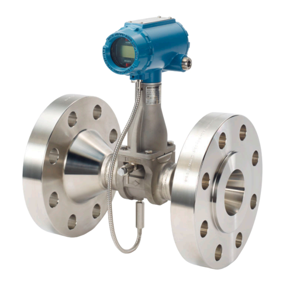
Reference Manual Introduction 00809-0400-4004 October 2021 Introduction Overview System description The Vortex Flow Meter consists of a meter body and transmitter, and measures volumetric flow rate by detecting the vortices created by a fluid passing by the shedder bar. The meter body is installed in-line with process piping. A sensor is located at the end of the shedder bar which creates a sine wave signal due to the passing vortices. - Page 10 Introduction Reference Manual October 2021 00809-0400-4004 ™ Rosemount 8800D Series Vortex Flow Meter with Modbus Protocol...
-
Page 11: Chapter 3 Pre-Installation
Vortex sizing software can be found using the Selection and Sizing tool. The Selection and Sizing tool can be accessed online or downloaded for offline use using this link: www.Emerson.com/FlowSizing. 3.1.2 Wetted material selection Ensure that the process fluid is compatible with the meter body wetted materials when specifying the Rosemount 8800D. - Page 12 Pre-installation Reference Manual October 2021 00809-0400-4004 Figure 3-1: Vertical installation A. Liquid or gas flow B. Gas flow Note To ensure the meter body remains full, avoid downward vertical liquid flows where back pressure is inadequate. Horizontal installation For horizontal installation, the preferred orientation is to have the electronics installed to the side of the pipe.
- Page 13 Reference Manual Pre-installation 00809-0400-4004 October 2021 Figure 3-3: Ambient/Process temperature limits 200 (93) 180(82) 160 (71) 140 (60) 120 (49) 100 (38) 80 (27) 60 (16) A. Ambient temperature °F (°C) B. Process temperature °F (°C) C. 185 °F (85 °C) Housing temperature limit. Note The indicated limits are for horizontal pipe and vertical meter position, with meter and pipe insulated with 3 in.
- Page 14 October 2021 00809-0400-4004 indicating the certifications they carry. For hazardous location installation, including Explosion-proof, Flameproof,or Intrinsic Safety (I.S.), please consult the Emerson 8800 Approval Document 00825-VA00-0001. Environmental considerations Avoid excessive heat and vibration to ensure maximum flow meter life. Typical problem areas include high-vibration lines with integrally mounted electronics, warm-climate installations in direct sunlight, and outdoor installations in cold climates.
-
Page 15: Commissioning
Reference Manual Pre-installation 00809-0400-4004 October 2021 Figure 3-6: Pressure and temperature transmitter location A. Pressure transmitter B. Four straight pipe diameters downstream C. Temperature transmitter D. Six straight pipe diameters downstream 3.1.5 Power supply The transmitter requires 10 to 30 VDC. The maximum power consumption is 0.4 W. Commissioning For proper configuration and operation, commission the meter before putting it into operation. - Page 16 Pre-installation Reference Manual October 2021 00809-0400-4004 Note If you will be changing configuration variables frequently, it may be useful to leave the security lockout jumper in the OFF position to avoid exposing the flow meter electronics to the plant environment. To access the jumpers, remove the transmitter electronics housing or the LCD cover (if equipped) opposite of the terminal block, See Figure 3-7...
-
Page 17: Chapter 4 Basic Installation
Reference Manual Basic installation 00809-0400-4004 October 2021 Basic installation Handling Handle all parts carefully to prevent damage. Whenever possible, transport the system to the installation site in the original shipping containers. Keep the shipping plugs in the conduit connections until you are ready to connect and seal them. NOTICE To avoid damage to the meter, do not lift the flow meter by the transmitter. -
Page 18: Insulation
Basic installation Reference Manual October 2021 00809-0400-4004 Insulation Insulation should extend to the end of the bolt on the bottom of the meter body and should leave at least 1-in. (25 mm) of clearance around the electronics bracket. The electronics bracket and electronics housing should not be insulated. See Figure 4-2. - Page 19 Reference Manual Basic installation 00809-0400-4004 October 2021 Figure 4-3: Flanged-style flow meter installation A. Installation studs and nuts (supplied by customer) B. Gaskets (supplied by customer) C. Flow Figure 4-4: Flange bolt torquing sequence Reference Manual...
-
Page 20: Wafer-Style Flow Meter Alignment And Mounting
Basic installation Reference Manual October 2021 00809-0400-4004 Wafer-style flow meter alignment and mounting Center the wafer-style meter body inside diameter with respect to the inside diameter of the adjoining upstream and downstream piping. This will ensure the flow meter achieves its specified accuracy. - Page 21 Reference Manual Basic installation 00809-0400-4004 October 2021 Figure 4-5: Wafer-style flow meter installation with alignment rings A. Installation studs and nuts (supplied by customer) B. Alignment rings C. Spacer (for Rosemount 8800D to maintain Rosemount 8800A dimensions) D. Flow Note See for instructions on retrofitting 8800D to 8800A installations.
-
Page 22: Cable Glands
Basic installation Reference Manual October 2021 00809-0400-4004 Table 4-2: Stud bolt length for wafer-style flow meters with EN 1092 flanges Line size Minimum recommended stud bolt lengths (in mm) for each flange rating PN 16 PN 40 PN 63 PN 100 DN 15 DN 25 DN 40... -
Page 23: Grounding The Transmitter Case
Reference Manual Basic installation 00809-0400-4004 October 2021 Note Properly ground flow meter body and transmitter per the local code. To use grounding straps, secure one end of the grounding strap to the bolt extending from the side of the meter body and attach the other end of each grounding strap to a suitable ground. -
Page 24: Conduit Installation
Basic installation Reference Manual October 2021 00809-0400-4004 ground the transmitter case. Do not run the transient protection ground wire with signal wiring as the ground wire may carry excessive electric current if a lightning strike occurs. 4.10 Conduit installation Prevent condensation in any conduit from flowing into the housing by mounting the flowmeter at a high point in the conduit run. -
Page 25: Remote Installation
Reference Manual Basic installation 00809-0400-4004 October 2021 Figure 4-8: Modbus and power supply wiring A. RS-485 (A) B. RS-485 (B) C. 10–30 VDC power supply 2. Connect Modbus RTU communication wires to the Modbus A and B terminals. Note Twisted pair wiring is required for RS-485 bus wiring. Wiring runs under 1000 ft (305 m) should be AWG 22 or larger. - Page 26 Basic installation Reference Manual October 2021 00809-0400-4004 4.12.2 Cable connections Complete these steps for connecting the loose end of the coaxial cable to the electronics housing. If connecting/disconnecting the meter adapter to the meter body,. Figure 4-9: Remote installation A. ½ NPT conduit adapter or cable gland (supplied by customer for Rxx options) B.
- Page 27 Reference Manual Basic installation 00809-0400-4004 October 2021 CAUTION To prevent moisture from entering the coaxial cable connections, install the interconnecting coaxial cable in a single dedicated conduit run or use sealed cable glands at both ends of the cable. In remote mount configurations when ordered with a hazardous area option code, the remote sensor cable and the interconnecting thermocouple cable are protected by separate intrinsic safety circuits, and must be segregated from each other, other intrinsically safe circuits, and non-intrinsically safe circuits per local and national wiring...
- Page 28 Basic installation Reference Manual October 2021 00809-0400-4004 Figure 4-10: Attaching and tightening SMA nut A. SMA nut B. Hand tighten Note Do not over-tighten the coaxial cable nut to the electronics housing. 10. Align the housing adapter with the housing and attach with two screws. 11.
- Page 29 Reference Manual Basic installation 00809-0400-4004 October 2021 7. Use a hex wrench to turn the housing rotation screws counter-clockwise (outward) to engage the support tube. 4.12.4 Specifications and requirements for remote sensor cable If using a Rosemount remote sensor cable, observe these specifications and requirements. •...
-
Page 30: Quad Transmitter Numbering And Orientation
Basic installation Reference Manual October 2021 00809-0400-4004 Figure 4-12: Armored cable A. Transmitter end B. Sensor end C. Minimum bend diameter 4.13 Quad transmitter numbering and orientation When quad vortex flow meters are ordered, for configuration purposes, the transmitters are identified as Transmitter 1, Transmitter 2, Transmitter 3, and Transmitter 4. The transmitter and meter body nameplate of a Quad Vortex flow meter can be used to identify and verify the transmitter number. - Page 31 Reference Manual Basic installation 00809-0400-4004 October 2021 Figure 4-13: Quad transmitter numbering A. Transmitter nameplate (Transmitter 1) B. Meter body nameplate (Transmitter 1) Reference Manual...
- Page 32 Basic installation Reference Manual October 2021 00809-0400-4004 Figure 4-14: Quad transmitter nameplate Figure 4-15: Quad meter body nameplate ™ Rosemount 8800D Series Vortex Flow Meter with Modbus Protocol...
-
Page 33: Chapter 5 Basic Configuration
• A HART communication tool must be used. Examples are ProLink III Software or AMS Software with a HART modem, or Emerson AMS Trex Device Communicator or 475 Field Communicator. • The transmitter leaves the factory at HART address 1. Verify that the HART communication tool is configured to poll beyond address 0. -
Page 34: Process Variables
Basic configuration Reference Manual October 2021 00809-0400-4004 Figure 5-1: HART configuration tool connection to COMM port A. Example AMS Trex Device Communicator B. Example ProLink III software on PC C. 10–30 VDC power supply If you do not have an external power supply during configuration, you can temporarily power the transmitter directly through the COMM terminals using the AMS Trex Device Communicator. - Page 35 Reference Manual Basic configuration 00809-0400-4004 October 2021 5.3.2 Process variable units Device Tools → Configuration → Process Measurement → ProLink III (select type) Allows for the viewing and configuration of Process Variable Units such as Volume, Velocity, Mass Flow, Electronics Temperature, Process Density, and Corrected Volume units, including corrected volume Special Units configuration.
-
Page 36: Process Configuration
Basic configuration Reference Manual October 2021 00809-0400-4004 Note When measuring corrected volumetric flow, a base density and process density must be provided. The base density and process density are used to calculate the density ratio which is a value used to convert actual volume flow to corrected volume flow. Mass flow units Allows the user to select the mass flow units from the available list. -
Page 37: Reference K-Factor
Device Tools → Configuration → Device Setup A factory calibration number relating the flow through the meter to the shedding frequency measured by the electronics. Every vortex meter manufactured by Emerson is run through a water calibration to determine this value. -
Page 38: Flange Type
Basic configuration Reference Manual October 2021 00809-0400-4004 Flange type ProLink III Device Tools → Configuration → Device Setup Enables the user to specify the type of flange on the flow meter for later reference. This variable is preset at the factory but can be changed if necessary. Table 5-4: Flange types Wafer ASME 150... -
Page 39: Optimize Digital Signal Processing (Dsp)
Reference Manual Basic configuration 00809-0400-4004 October 2021 Table 5-5: Pipe IDs for Schedule 10, 40, and 80 piping Pipe size inches (mm) Schedule 10 inches Schedule 40 inches Schedule 80 inches (mm) (mm) (mm) ½ (15) 0.674 (17,12) 0.622 (15,80) 0.546 (13,87) 1 (25) 1.097 (27,86) - Page 40 Basic configuration Reference Manual October 2021 00809-0400-4004 Table 5-6: Modbus default and configurable communication settings (continued) Parameter Rosemount HMC Default Configurable values 8800D settings default settings Address range 1–247 If the transmitter was ordered without communication settings, these will be configured at the factory.
- Page 41 Reference Manual Basic configuration 00809-0400-4004 October 2021 Write HART Message field for HART address 1 device per Table 5-7. Note Cycle power after sending the message and wait 60 seconds after the power is restored for changes to take effect. Table 5-7: Modbus alarm configuration settings String Alarm output...
- Page 42 Basic configuration Reference Manual October 2021 00809-0400-4004 ™ Rosemount 8800D Series Vortex Flow Meter with Modbus Protocol...
-
Page 43: Chapter 6 Advanced Installation
Reference Manual Advanced installation 00809-0400-4004 October 2021 Advanced installation Insert integral temperature sensor Follow these steps to install the integral temperature sensor, if equipped. 1. The temperature sensor is coiled and attached to the electronics bracket. Remove the Styrofoam around the sensor and insert the temperature sensor into the hole at the bottom of the meter body. -
Page 44: Pulse Output
Advanced installation Reference Manual October 2021 00809-0400-4004 4. Hold the temperature sensor in place and tighten the bolt with a ½ inch (13 mm) open end wrench until it reaches ¾ turns past finger tight. Do not over-tighten. 5. Verify that the insulation extends to the end of the bolt on the bottom of the meter body. -
Page 45: Transient Protection
Reference Manual Advanced installation 00809-0400-4004 October 2021 Figure 6-3: 4–20 mA and pulse wiring with electronic totalizer/counter >250 Ω A. Power supply B. Counter power supply C. Counter Transient protection The optional transient terminal block prevents damage to the flowmeter from transients induced by lightning, welding, heavy electrical equipment, or switch gears. - Page 46 Advanced installation Reference Manual October 2021 00809-0400-4004 Refer to the following figure. 4. Remove the housing ground screw. 5. Use pliers to pull the terminal block out of the housing. 6. Inspect the connector pins for straightness. 7. Place the new terminal block in position and carefully press it into place. The terminal block may have to be moved back and forth to get the connector pins started into the sockets.
-
Page 47: Chapter 7 Advanced Configuration
Reference Manual Advanced configuration 00809-0400-4004 October 2021 Advanced configuration Advanced configuration options are used to configure the flow meter for a wider range of applications and special situations. LCD display ProLink III Device Tools → Configuration → Display Variables The LCD display (option M5) provides local indication of the output and abbreviated diagnostic messages governing operation of the flow meter. -
Page 48: Meter Body
Advanced configuration Reference Manual October 2021 00809-0400-4004 Meter body ProLink III Device Tools → Configuration → Informational Parameters → Meter Body Meter body parameters are factory-set configuration variables that indicate the physical and manufacturing properties of the flow meter. These parameters need not be changed unless the transmitter is being configured in the field for use with a different meter body than originally configured. -
Page 49: Pulse Output
Reference Manual Advanced configuration 00809-0400-4004 October 2021 • Cold Junction Temperature (MTA) • Totalizer Value • Shedding Frequency • Mass Flow • Velocity Flow • Volume Flow • Process Temperature (MTA) • Pulse Frequency • Electronics Temperature • Signal Strength •... -
Page 50: Signal Processing
Advanced configuration Reference Manual October 2021 00809-0400-4004 mating pipe inside diameters. Scaled pulse mode must be used to compensate the K- factor for thermal expansion and mating pipe effects. Scaled volumetric This mode allows for configuration of the pulse output based on a volumetric flow rate. For example, set 100 gallons per minute = 10,000 Hz. - Page 51 4–20 mA trim, pulse scaling factor, process temperature, pipe ID), refer to Troubleshooting. If problems persist after signal processing adjustments, contact an Emerson representative (see back page). Optimize DSP (Digital Signal Processing) Used to optimize the range of the flow meter based on the density of the fluid.
- Page 52 • Increase Low Pass Corner Frequency Note Do not adjust this parameter unless directed to do so by an Emerson representative. Trigger level Configured to reject noise within the flow range while allowing normal amplitude variation of the vortex signal. Signals of amplitude lower than the Trigger Level setting are filtered out.
-
Page 53: Special Process Variable Units
Reference Manual Advanced configuration 00809-0400-4004 October 2021 Temperature damping The default damping value is 2.0 seconds. Temperature Damping can be reset to any value between 0.4 and 32 seconds. Temperature Damping can only be configured if Temperature is assigned to be PV. Special process variable units Device Tools →... -
Page 54: Flow Totalizer
Advanced configuration Reference Manual October 2021 00809-0400-4004 Special flow unit A user created custom flow unit. The special unit is limited to four characters. The LCD display will display the actual four character user defined special unit. Conversion number Used to relate base units to special units. For a straight conversion of volume units from one to another, the conversion number is the number of base units in the new unit. - Page 55 Reference Manual Advanced configuration 00809-0400-4004 October 2021 Note In order to totalize in compensated mass flow, set pulse output to Scaled Mass even if the pulse output was not ordered or will not be used. Please refer to section 7.9 for pulse output configuration.
- Page 56 Advanced configuration Reference Manual October 2021 00809-0400-4004 ™ Rosemount 8800D Series Vortex Flow Meter with Modbus Protocol...
-
Page 57: Chapter 8 Troubleshooting
3. Verify that the transmitter is not set to Burst Mode. 4. Cycle power and try again. 5. The device may require component replacement or advanced troubleshooting service. Contact an Emerson representative for assistance. Incorrect Modbus communication output Before troubleshooting communication problems, ensure that 10–30 VDC is applied to the transmitter + and –... -
Page 58: Incorrect Pulse Output
1. Check sizing. Make sure the flow is within measurable flow limits. Use the online Emerson Size and Selection tool for best sizing results. 2. Check to make sure the meter is installed with the arrow in the direction of process flow. -
Page 59: No Flow, Output
Recommended actions for application problems 1. Check sizing. Make sure the flow is within measurable flow limits. Use the online Emerson Size and Selection tool for best sizing results. 2. Calculate the expected frequency. If the actual frequency is the same, check the configuration. -
Page 60: Diagnostic Messages
Troubleshooting Reference Manual October 2021 00809-0400-4004 3. Check the shedding frequency to see if it is locked to 50/60 Hz for AC line noise. Remote installations are more susceptible. 4. Verify line is blocked or fully shut down 5. Check to make sure the meter is installed with the arrow in the direction of process flow. - Page 61 Reference Manual Troubleshooting 00809-0400-4004 October 2021 Table 8-1: Faults (continued) Display ProLink III Description FAULt^^^ Non-Volatile Memory Error At least one segment of non-volatile memory has failed a checksum verification. If the 'Factory Non-Volatile Memory Error' is NOT also NVMEM active this problem may be fixed by reconfiguring all transmitter parameters.
- Page 62 Troubleshooting Reference Manual October 2021 00809-0400-4004 Table 8-1: Faults (continued) Display ProLink III Description FAULt^^^ Process Temperature is above The Process Temperature is above the high limit for Saturated the Saturated Steam Limits Steam density calculations. This status only occurs when the PT>CF Process Fluid is Temperature Compensated Saturated Steam.
-
Page 63: Electronics Test Points
Reference Manual Troubleshooting 00809-0400-4004 October 2021 Table 8-3: Advisory Display ProLink III Description SIGnAL^^ Flow Simulation Mode The flow signal is being produced from a signal generator internal to the Vortex transmitter. The flow value reported by the SIMUL transmitter is NOT the process flow value. •... - Page 64 Troubleshooting Reference Manual October 2021 00809-0400-4004 Electronics verification. To verify the electronics, you can input a frequency on the TEST FREQ IN and GROUND pins to simulate flow via an external signal source such as a frequency generator. To analyze and/or troubleshoot the electronics, an oscilloscope (set for AC coupling) and a handheld communicator or AMS Device Manager interface are required.
- Page 65 Reference Manual Troubleshooting 00809-0400-4004 October 2021 Figure 8-3: Clean signals 3.0V A. Vortex signal (TP1) B. Trigger level C. Shedding frequency output Examples: Wrong waveforms Figure 8-4 Figure 8-5 show waveforms that may cause the output to be inaccurate. Figure 8-4: Noisy signals 3.0 V A.
- Page 66 Troubleshooting Reference Manual October 2021 00809-0400-4004 Figure 8-5: Improper Sizing/Filtering 3.0V A. Vortex signal (TP1) B. Trigger level C. Shedding frequency output ™ Rosemount 8800D Series Vortex Flow Meter with Modbus Protocol...
-
Page 67: Chapter 9 Maintenance
Reference Manual Maintenance 00809-0400-4004 October 2021 Maintenance Transient protection The optional transient terminal block prevents damage to the flowmeter from transients induced by lightning, welding, heavy electrical equipment, or switch gears. The transient protection electronics are located in the terminal block. IEEE C62.41 - 2002 Category B The transient terminal block was verified using the following test waveforms specified in the IEEE C62.41 - 2002 Category B standard:... -
Page 68: Installing The Lcd Indicator
Maintenance Reference Manual October 2021 00809-0400-4004 Figure 9-1: Transient Terminal Block A. Housing ground screw B. Captive screws C. Transient terminal block ground tab 9.1.2 Reconfiguring the Modbus module parameters Modbus communication settings. Installing the LCD indicator For flowmeters ordered with the LCD indicator, the indicator is shipped installed. When purchased separately from the Rosemount 8800D, you must install the indicator using a small instrument screwdriver and the indicator kit. - Page 69 Reference Manual Maintenance 00809-0400-4004 October 2021 • One connector • Two mounting screws • Two jumpers Refer to the following figure when using these steps to install the LCD indicator: A. Electronics board 1. If the flowmeter is installed in a loop, secure the loop and disconnect the power. 2.
-
Page 70: Hardware Replacement
Maintenance Reference Manual October 2021 00809-0400-4004 • Storage: –50 to 185 °F (–46 to 85 °C) Hardware replacement The following procedures will help you disassemble and assemble the Rosemount 8800D hardware if you have followed the troubleshooting guide earlier in this section of the manual and determined that hardware components need to be replaced. - Page 71 Reference Manual Maintenance 00809-0400-4004 October 2021 Figure 9-2: Terminal block assembly A. Cover B. O-ring C. Terminal block D. Captive screws (3x) 3. Disconnect the wires from the field terminals. Be sure to secure them out of the way. 4. Remove the ground screw. 5.
- Page 72 Maintenance Reference Manual October 2021 00809-0400-4004 Remove the electronics boards 1. Turn off the power to the Rosemount 8800D. 2. Unscrew and remove the electronics board compartment cover. (Unscrew and remove the LCD display cover if you have the LCD display option). Figure 9-3: Electronics Boards Assembly A.
- Page 73 Reference Manual Maintenance 00809-0400-4004 October 2021 6. Reinsert the alarm and security jumpers into the correct location. 7. Re-install the thermocouple if applicable. 8. If the meter has LCD display option, insert the connector header into the LCD display board. a) Remove jumpers from the electronics board.
- Page 74 Maintenance Reference Manual October 2021 00809-0400-4004 Install the electronics housing 1. Verify that power to the Rosemount 8800D is off. 2. Screw the sensor cable nut onto the base of the housing. 3. Tighten the sensor cable nut with a 5/16 inch (8 mm) open end wrench. 4.
- Page 75 Reference Manual Maintenance 00809-0400-4004 October 2021 Note Sensor cavity could contain line pressure if an abnormal failure has occurred inside the meter body. For complete warning information, see Safety messages. ™ 1. If the meter body is not a CriticalProcess Vortex (CPA Option) proceed to Step 2.
- Page 76 Maintenance Reference Manual October 2021 00809-0400-4004 Figure 9-4: Removable support tube assembly A. Removable support tube B. Sensor nut C. Sensor D. Anchor bolts E. Meter body 9. Remove the support tube. 10. Loosen and remove the sensor nut from the sensor cavity with a 1-1/8 in (28 mm) open end wrench.
- Page 77 Reference Manual Maintenance 00809-0400-4004 October 2021 scratch or otherwise damage any part of the sensor, sensor cavity, or sensor nut threads. Damage to these parts may require replacement of the sensor or meter body, or may render the flowmeter dangerous. Note If you are installing a sensor that has been used before, clean the metal o-ring on the sensor using the procedure below.
- Page 78 Maintenance Reference Manual October 2021 00809-0400-4004 Figure 9-6: Sensor installation – improper alignment (before seating) A. Top view of flowmeter B. Sensor C. Sensor cavity in flowmeter D. Sensor not properly aligned E. Sensor center line is not aligned with flowmeter center line. Damage to sensor will occur.
- Page 79 Reference Manual Maintenance 00809-0400-4004 October 2021 3. Sensor should remain as close to vertical as possible when applying force to seat. Figure 9-8. Figure 9-8: Sensor installation – applying force A. Pressure B. Sensor center line must be aligned with flowmeter center line C.
- Page 80 Maintenance Reference Manual October 2021 00809-0400-4004 3. Slowly pull the meter adapter no more than 1.5 inch (40 mm) from the top of the support tube. 4. Loosen and disconnect the sensor cable nut from the union using a 5/16 inch (8 mm) open end wrench.
- Page 81 Reference Manual Maintenance 00809-0400-4004 October 2021 3. Loosen and disconnect the conduit adapter or cable gland from the meter adapter. Attach the meter adapter 1. If you are using a conduit adapter or cable gland, slide it over the plain end of the coaxial cable (the end without a ground wire).
- Page 82 Maintenance Reference Manual October 2021 00809-0400-4004 Figure 9-10: Remote electronics exploded view A. Ground connection B. Housing base screw C. Housing adapter D. Housing adapter screws E. Conduit adapter (optional—supplied by customer) F. Coaxial cable nut G. Electronics housing Attach the coaxial cable 1.
- Page 83 Reference Manual Maintenance 00809-0400-4004 October 2021 9.3.6 Changing the housing orientation The entire electronics housing may be rotated in 90 degree increments for better wiring access or improved viewing of the display. 1. Loosen the screw on the access cover on the support tube (if present) and remove the cover.
-
Page 84: Return Of Material
The Rosemount North American Response Center will detail the additional information and procedures necessary to return goods exposed to hazardous substances. Toll-free assistance numbers Within the United States, Emerson Process Management has two toll-free assistance numbers: Technical support, quoting, and order-related questions: 1-800-522-6277 (7:00 am to 7:00 pm CST) North American Response Center—Equipment service needs:... - Page 85 Reference Manual Maintenance 00809-0400-4004 October 2021 Outside of the United States, contact your local an Emerson Flow Sales Representative . Reference Manual...
- Page 86 Maintenance Reference Manual October 2021 00809-0400-4004 ™ Rosemount 8800D Series Vortex Flow Meter with Modbus Protocol...
-
Page 87: Appendix A Product Specifications
Liquid, Gas, and Steam applications. Fluids must be homogeneous and single-phase. Flow calibration Every Emerson Vortex flowmeter is water calibrated and given a unique calibration number called a reference K-factor. Emerson flow labs use traceable calibrations that reference internationally recognized standards such as NIST in the United States and Mexico, National Institute of Standards in China, and ISO 10725 in Europe. - Page 88 Product Specifications Reference Manual October 2021 00809-0400-4004 For a weld-end style meter, see Table A-5. Pressure limits Table A-2: Flanged/Dual/Quad style meter ASME 16.5 EN1092-1 Class 150 PN 10 Class 300 PN 16 Class 600 PN 25 Class 900 PN 40 Class 1500 PN 63 PN 100...
- Page 89 Contact an Emerson Flow representative (see back page). The Super Duplex material of construction is limited to use in applications with process temperatures from –40 to +450 °F (–40 to +232 °C). Contact an Emerson Flow representative (see back page).
- Page 90 Product Specifications Reference Manual October 2021 00809-0400-4004 Table A-9: Electronics temperature limits (integrally-mounted transmitter) (continued) Maximum process temperature Interdependent with ambient temperature. Figure A-1 indicates the combined ambient and process temperature limits under which the electronics temperature can be maintained below the maximum +185 °F (+85 °C).
-
Page 91: Performance Specifications
Reference Manual Product Specifications 00809-0400-4004 October 2021 Remote transmitter mounting hardware and cables • Mounting hardware is provided. • The transmitter and meter body are interconnected by a standard or armored signal cable assembly. — Cable length is specified when ordered (see Ordering Information - Single/Dual Transmitter Ordering information –... - Page 92 • For all dual shedder bar design meters: max velocity of 100 ft/s (30.5 m/s) • For dual shedder bar design meters above 100 ft/s (30.5 m/s) contact an Emerson Flow representative (see back page). Volume flow repeatability ±0.1 percent of actual flow rate.
- Page 93 Reference Manual Product Specifications 00809-0400-4004 October 2021 Process temperature effect on K-factor The compensated K-factor is based on the reference K-factor as compensated for the given fixed process temperature and wetted materials. Compensated K-factor is calculated by the electronics. The percentage change in K-factor for all materials is no greater than ±0.3 per 100 °F (56 °C).
- Page 94 Rosemount 8800D Product Page, and select Size for detailed sizing on most applications, or complete a Configuration Data Sheet and contact an Emerson Flow representative (see back page). The PPL is determined using the equation: A × ρ × Q ƒ...
- Page 95 Reference Manual Product Specifications 00809-0400-4004 October 2021 Where: Line pressure five pipe diameters downstream of the meter (psia or kPa abs) ΔP Pressure loss across the meter (psi or kPa) Liquid vapor pressure at operating conditions (psia or kPa abs) Vibration effect High vibration may cause a false flow measurement when there is no flow.
-
Page 96: Typical Flow Rates
Typical flow rates This section provides typical flow ranges for some common process fluids with default filter settings. Consult an Emerson representative (see back page) to obtain a computer sizing program that describes in greater detail the flow range for an application. - Page 97 Reference Manual Product Specifications 00809-0400-4004 October 2021 Table A-17: Typical pipe velocity ranges for Rosemount 8800D and 8800DR (continued) Process line size Vortex meter Liquid velocity ranges Gas velocity ranges (inches/ DN) (ft/s) (m/s) (ft/s) (m/s) 8800DR100 0.44 to 15.9 0.13 to 4.8 4.12 to 158.6 1.26 to 48.3...
- Page 98 Product Specifications Reference Manual October 2021 00809-0400-4004 Table A-19: Air flow rate limits at 59 °F (15 °C) Process pressure Flow Minimum and maximum air flow rates for line sizes 1/2-in./DN 15 through 1- rate in./DN 25 limits 1/2-in./DN 15 1-in./DN 25 Rosemount 8800D Rosemount Rosemount 8800D Rosemount...
- Page 99 Reference Manual Product Specifications 00809-0400-4004 October 2021 Table A-20: Air flow rate limits at 59 °F (15 °C) (continued) Process pressure Flow Minimum and maximum air Flow rates for line sizes 11/2-in./DN 40 through 2- rate in./DN 50 limits 11/2-in./DN 40 2-in./DN 50 Rosemount 8800D Rosemount Rosemount 8800D Rosemount...
- Page 100 Product Specifications Reference Manual October 2021 00809-0400-4004 Table A-22: Air flow rate limits at 59 °F (15 °C) Process pressure Flow Minimum and maximum air flow rates for line sizes 6-in./DN 150 through 8-in./DN rate limits 6-in./DN 150 8-in./DN 200 Rosemount 8800D Rosemount Rosemount 8800D Rosemount 8800DR...
- Page 101 Reference Manual Product Specifications 00809-0400-4004 October 2021 Table A-23: Saturated steam flow rate limits (assumes steam quality is 100%) (continued) Process pressure Flow Minimum and maximum saturated steam flow rates for line sizes 1/2-in./DN 15 rate through 1-in./DN 25 limits 1/2-in./DN 15 1-in./DN 25 Rosemount 8800D Rosemount...
- Page 102 Product Specifications Reference Manual October 2021 00809-0400-4004 Table A-24: Saturated steam flow rate limits (assumes steam quality is 100%) (continued) Process pressure Flow Minimum and maximum saturated steam flow rates for line sizes 1/2-in./DN 15 rate through 1-in./DN 25 limits 11/2-in./DN 40 2-in./DN 50 Rosemount 8800D Rosemount...
- Page 103 Reference Manual Product Specifications 00809-0400-4004 October 2021 Table A-25: Saturated steam flow rate limits (assumes steam quality is 100%) (continued) Process pressure Flow Minimum and maximum saturated steam flow rates for line sizes 3-in./DN 80 rate through 4-in./DN 100 limits 3-in./DN 80 4-in./DN 100 Rosemount 8800D Rosemount...
-
Page 104: Hart Specifications
Product Specifications Reference Manual October 2021 00809-0400-4004 Table A-27: Saturated steam flow rate limits (assumes steam quality is 100%) Process pressure Flow Minimum and maximum saturated steam flow rates for line sizes 10-in./DN 250 rate through 12-in./DN 300 limits 10-in./DN 250 12-in./DN 300 Rosemount 8800D Rosemount Rosemount 8800D Rosemount... - Page 105 Reference Manual Product Specifications 00809-0400-4004 October 2021 Scalable frequency adjustment The scalable pulse output can be set to a specific velocity, volume, or mass (i.e. 1 pulse = 1 lb). The scalable pulse output can also be scaled to a specific rate of volume, mass, or velocity (i.e.
- Page 106 Product Specifications Reference Manual October 2021 00809-0400-4004 Table A-28: mA outputs for low and high alarm Alarm jumper mA output by Alarm Type setting position Rosemount standard NAMUR-compliant 3.75 3.60 21.75 22.6 The Alarm and Saturation Type settings can be pre-configured at the factory (Options C4 and CN for NAMUR-compliance) or user-configured.
- Page 107 Reference Manual Product Specifications 00809-0400-4004 October 2021 Low flow cutoff Optimized at the factory per the user's process conditions per Rosemount 8800D Configuration Data Sheet (00806-0100-4004) and typically required no adjustment. In certain cases, if required, it can be further adjusted after installation. Below selected value, output is driven to 4 mA and zero pulse output frequency.
-
Page 108: Modbus Rs-485 Specifications
Product Specifications Reference Manual October 2021 00809-0400-4004 Modbus RS-485 specifications Modbus output is provided by a HART to Modbus output conversion. Output signals The Rosemount 8800 communicates via Modbus (RS-485) providing device status and 4 dynamic variables. Communication uses 1 start bit and 8 data bits. Baud rates supported are 1200, 2400, 4800, 9600, 19200, and 38400. - Page 109 Reference Manual Product Specifications 00809-0400-4004 October 2021 Figure A-3: Examples ALARM ALARM ALARM ALARM ALARM ALARM TEMP FLOW SECURITY SECURITY SECURITY SECURITY SECURITY SECURITY When more than one item is selected, the display will scroll through all items selected. In the event of a fault, the display shows the applicable fault code.
-
Page 110: Quality Certificate Details
Product Specifications Reference Manual October 2021 00809-0400-4004 Quality certificate details Table A-30: Weld examination certifications for Q70, Q71 Helium Dye pen Radio- CD of report report graphic images report 8800DF/8800DD/8800DQ Form Q70, Inspection Certificate Weld Examination, ISO 10747.3.1 ✔ ✔ 0.5 inch 15 mm ✔... - Page 111 Reference Manual Product Specifications 00809-0400-4004 October 2021 Table A-31: PMI Code Q76 for X-Ray Fluorescent Spectrometry (XFR) Alloy Elements to be identified 316L Stainless Steel Cr (Chromium), Ni (Nickel), Mo (Molybdenum) NiB (Nickel based) Alloys Cr (Chromium), Ni (Nickel), Mo (Molybdenum) 25Cr Super Duplex Cr (Chromium), Ni (Nickel), Mo (Molybdenum) Table A-32: PMI Code Q77 for Optical Emission Spark Spectrometry (OES)
- Page 112 Product Specifications Reference Manual October 2021 00809-0400-4004 ™ Rosemount 8800D Series Vortex Flow Meter with Modbus Protocol...
-
Page 113: Appendix B Spacers
Reference Manual Spacers 00809-0400-4004 October 2021 Spacers Spacers are available with the Rosemount 8800D to maintain the Rosemount 8800A dimensions. Spacers are installed downstream from the meter body. The spacer kit comes with an alignment ring for ease of installation. Gaskets are placed on each side of the spacer. - Page 114 Spacers Reference Manual October 2021 00809-0400-4004 ™ Rosemount 8800D Series Vortex Flow Meter with Modbus Protocol...
-
Page 115: Appendix C Electronics Verification
Reference Manual Electronics verification 00809-0400-4004 October 2021 Electronics verification 8800D electronics verification is done using either the internal signal simulation capability, or by applying an external signal source to the TEST FREQ IN and GROUND pins. Electronics functionality is verified via two different verification methods: •... -
Page 116: Fixed Flow Rate Simulation
Electronics verification Reference Manual October 2021 00809-0400-4004 Fixed flow rate simulation The fixed flow simulation signal is entered in either percent of range or flow rate in engineering units. The resulting flow rate and/or shedding frequency can be continuously monitored using a HART communication device or an AMS Device Manager. Varying flow rate simulation The profile of the varying flow simulation signal is a repetitive triangular waveform as illustrated in the following figure. - Page 117 Reference Manual Electronics verification 00809-0400-4004 October 2021 This option is used with an external frequency generator to disconnect the Rosemount 8800D sensor input from the charge amplifier input of the electronics (see Figure C-2). The simulated flow and/or the shedding frequency values are now accessible using a HART communication device or AMS Device Manager.
-
Page 118: Output Variable Calculations With Known Input Frequency
Electronics verification Reference Manual October 2021 00809-0400-4004 Output variable calculations with known input frequency Use the following equations with a known input frequency to verify a flow rate or a 4–20 mA output within a given calibrated range. Select the proper equation depending on whether you are verifying a flow rate, mass flow rate, 4–20 mA output, or special units. -
Page 119: Unit Conversion Table
Reference Manual Electronics verification 00809-0400-4004 October 2021 Unit conversion table Use the following table when converting units of measure. Unit conversions Units (actual) Conversion factor gal/s 1.00000E+00 gal/m 1.66667E-02 gal/h 2.77778E-04 Impgal/s 1.20095E+00 Impgal/m 2.00158E-02 Impgal/h 3.33597E-04 2.64172E-01 4.40287E-03 7.33811E-05 CuMtr/m 4.40287E+00 CuMtr/h... - Page 120 Electronics verification Reference Manual October 2021 00809-0400-4004 Line size 3 inch Line pressure 100 psi Vortex frequency 75 Hz 500 gpm 0 gpm 1.66667E-02 (from Unit conversion table) K-factor 10.79 pulses/gallon using a HART communication device or AMS Device compensated Manager Q = F/(K ×...
- Page 121 Reference Manual Electronics verification 00809-0400-4004 October 2021 F/(K x C 400/ {10.678 x (C /ρ)} 400/{10.678 x (0.00207792/1.078)} 400/(10.678 x 0.0019276) 19433.6 lb/hr An input frequency of 400 Hz represents a flow rate of 19433.6 lb/hr in this application. For a given input frequency, you can also determine the electrical current output. Use the values in the previous table with an input frequency of 300 Hz: 300 Hz F/(K ×...
- Page 122 Electronics verification Reference Manual October 2021 00809-0400-4004 F/(K × C − LRV) × (16) + 4 URV − LRV 200/(10.797 × 0.011641) − 0) × (16) + 4 5833−0 I = 8.36mA An input frequency of 200 Hz represents an electrical current output of 8.36 mA. C.7.2 SI unit examples Example 1...
- Page 123 Reference Manual Electronics verification 00809-0400-4004 October 2021 Operating temp 77 °C Viscosity 0.015 cp Input frequency 650 Hz K-factor (compensated) 10.715 pulses/gallon using HART communication device or AMS Device Manager 3600 kg/hr 0 kg/hr /ρ (from Unit conversion table) F(Hz) /(K x C 650/{10.715 x (C11/ρ)} 650/{10.715 x (0.0733811/4.169)} 650/(10.715 x 0.017602)
- Page 124 Electronics verification Reference Manual October 2021 00809-0400-4004 Density ration 10.48 F/K x C where C /(density ratio) 700/{10.797 x (.0733811/10.48)} 9259.2 NCMH An input frequency of 700 Hz represents a flow rate of 9259.2 NCMH in this application. For a given input frequency, you can also determine the electrical current output. Use the values in the previous table with an input frequency of 375 Hz.
-
Page 125: Appendix D Modbus Details
Reference Manual Modbus details 00809-0400-4004 October 2021 Modbus details Byte transmission order When using Modbus RTU, the registers to receive status and variables must be correctly configured in the host system. The transmission of single-precision (4 bytes) IEEE 754 floating point numbers can be rearranged in different byte orders specified by the Floating Point Format Code. - Page 126 Modbus details Reference Manual October 2021 00809-0400-4004 Table D-2: Registers for floating point format code 0 Register name Register number Note Slave Status 2000 Bit information in bit field. • Bit 0: Invalid Measurement Slave PV. • Bit 1: Invalid Measurement Slave SV. •...
- Page 127 Reference Manual Modbus details 00809-0400-4004 October 2021 Table D-3: Registers for floating point format code 1 (continued) Register name Register number Note Slave SV Conf 1304 Secondary variable from slave represented in IEEE 754 format, using Floating Point Format Code 1. Slave TV Conf 1306 Tertiary variable from slave represented in IEEE...
-
Page 128: Holding Registers (Modbus Function Code 3)
Modbus details Reference Manual October 2021 00809-0400-4004 Table D-5: Registers for floating point format code 3 Register name Register number Note Slave Status 2200 Bit information in bit field. • Bit 0: Invalid Measurement Slave PV. • Bit 1: Invalid Measurement Slave SV. •... - Page 129 Reference Manual Modbus details 00809-0400-4004 October 2021 Table D-6: Registers for floating point format code 0 Register name Register number Note Slave Status 7000 Bit information in bit field. • Bit 0: Invalid Measurement Slave PV. • Bit 1: Invalid Measurement Slave SV. •...
- Page 130 Modbus details Reference Manual October 2021 00809-0400-4004 Table D-7: Registers for floating point format code 1 (continued) Register name Register number Note Slave SV Conf 6304 Secondary variable from slave represented in IEEE 754 format, using Floating Point Format Code 1. Slave TV Conf 6306 Tertiary variable from slave represented in IEEE...
- Page 131 Reference Manual Modbus details 00809-0400-4004 October 2021 Table D-9: Registers for floating point format code 3 Register name Register number Note Slave Status 7200 Bit information in bit field. • Bit 0: Invalid Measurement Slave PV. • Bit 1: Invalid Measurement Slave SV. •...
- Page 132 *00809-0400-4004* 00809-0400-4004 Rev. AB 2021 For more information: www.emerson.com © 2021 Rosemount, Inc. All rights reserved. The Emerson and Rosemount logos are trademarks and service marks of Emerson Electric Co. All other marks are property of their respective owners.
Need help?
Do you have a question about the Rosemount 8800D Series and is the answer not in the manual?
Questions and answers