Emerson Rosemount 8800D Series Reference Manual
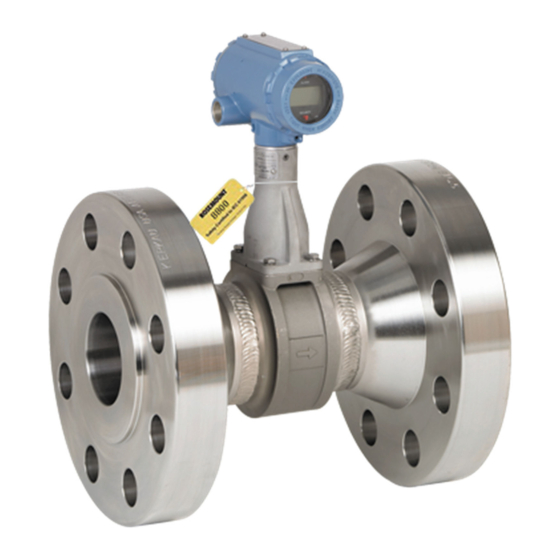
Vortex flowmeter with foundation fieldbus
Hide thumbs
Also See for Rosemount 8800D Series:
- Reference manual (188 pages) ,
- Quick start manual (56 pages) ,
- Quick installation manual (31 pages)
Table of Contents
Troubleshooting

Related Manuals for Emerson Rosemount 8800D Series


Summary of Contents for Emerson Rosemount 8800D Series
- Page 1 Aotewell Ltd www.aotewell.com Industry Automation Reference Manual 00809-0100-4772, Rev FA March 2016 ™ Rosemount 8800D Series Vortex Flowmeter ™ with F Fieldbus OUNDATION sales@aotewell.com +86-755-8660-6182 HongKong|UK|China...
- Page 2 Aotewell Ltd www.aotewell.com Industry Automation sales@aotewell.com +86-755-8660-6182 HongKong|UK|China...
-
Page 3: Table Of Contents
Aotewell Ltd www.aotewell.com Industry Automation Reference Manual Table of Contents 00809-0100-4772, Rev FA March 2016 Contents 1Section 1: Introduction Using this manual ........... . . 1 Fieldbus technology . - Page 4 Aotewell Ltd www.aotewell.com Industry Automation Reference Manual Table of Contents 00809-0100-4772, Rev FA March 2016 2.7.18 VEL_MEAS_BASE ..........15 2.7.19 TC_FAILURE_MODE.
- Page 5 Aotewell Ltd www.aotewell.com Industry Automation Reference Manual Table of Contents 00809-0100-4772, Rev FA March 2016 3.5.5 Wafer-style flowmeter alignment and mounting ....31 3.5.6 Flanged-style flowmeter mounting .
- Page 6 Aotewell Ltd www.aotewell.com Industry Automation Reference Manual Table of Contents 00809-0100-4772, Rev FA March 2016 5.1.1 Definition ........... . 65 Parameters and descriptions .
- Page 7 Aotewell Ltd www.aotewell.com Industry Automation Reference Manual Table of Contents 00809-0100-4772, Rev FA March 2016 Dimensional drawings ..........116 BAppendix B: Product Certifications Product certifications.
- Page 8 Aotewell Ltd www.aotewell.com Industry Automation Reference Manual Table of Contents 00809-0100-4772, Rev FA March 2016 DAppendix D: Alerts Alerts............. 161 PlantWeb alerts overview .
- Page 9 Read this manual before working with the product. For personal and system safety, and for optimum product performance, make sure you thoroughly understand the contents before installing, using, or maintaining this product. Within the United States, Emerson Process Management has two toll-free assistance numbers: Customer Central Technical support, quoting, and order-related questions.
- Page 10 Aotewell Ltd www.aotewell.com Industry Automation Reference Manual Title Page 00809-0100-4772, Rev FA March 2016 Title Page HongKong|UK|China sales@aotewell.com +86-755-8660-6182...
-
Page 11: Using This Manual
Aotewell Ltd www.aotewell.com Industry Automation Introduction Reference Manual March 2016 00809-0100-4772, Rev FA Section 1 Introduction Using this manual The sections in this manual provide information on installing, configuring, troubleshooting, ™ and performing other procedures for the Rosemount 8800D Vortex Flowmeter with ™... -
Page 12: System Description
Aotewell Ltd www.aotewell.com Industry Automation Reference Manual Introduction 00809-0100-4772, Rev FA March 2016 environments. The fieldbus environment is the base level group of digital networks in the hierarchy of plant networks. The fieldbus retains the desirable features of the 4–20 mA analog system, including a standardized physical interface to the wire, bus-powered devices on a single pair of wires, and intrinsic safety options. -
Page 13: Overview
Aotewell Ltd www.aotewell.com Industry Automation Configuration and Operation Reference Manual March 2016 00809-0100-4772, Rev FA Section 2 Configuration and Operation Overview ..............page 3 Safety messages . -
Page 14: User Interfaces
Device Descriptors (DDs) and DTM files for Rosemount products are available on the Emerson Install Kits website. The DD capabilities supported will vary based on host supplier and host revision. Check with the host supplier to determine and obtain the appropriate DD for your situation. - Page 15 Aotewell Ltd www.aotewell.com Industry Automation Reference Manual Configuration and Operation 00809-0100-4772, Rev FA March 2016 Flow Damping Fixed Process Temperature Fixed Process Density and Density Units Density Ratio (for Standard or Normal flow units only) If transmitter functional verification is required, refer to Appendix C: Electronics Verification.
- Page 16 Aotewell Ltd www.aotewell.com Industry Automation Reference Manual Configuration and Operation 00809-0100-4772, Rev FA March 2016 Figure 2-1. General Guide for Commissioning and Meter Installation Bench START HERE Commissioning CONFIGURE FIELD INSTALL Review Configuration Mount Transmitter Configuration Flowmeter Mode Process Fluid Mount Conduit Go to...
-
Page 17: General Block Information
Aotewell Ltd www.aotewell.com Industry Automation Reference Manual Configuration and Operation 00809-0100-4772, Rev FA March 2016 General block information Reference information on the process control function blocks can be found in the Function Block manual document number 00809-0100-4783. 2.5.1 Modes of operation The Resource, Transducer, and all other function blocks in the device have modes of operation. -
Page 18: Block Instantiation
Aotewell Ltd www.aotewell.com Industry Automation Reference Manual Configuration and Operation 00809-0100-4772, Rev FA March 2016 Permitted modes It is possible to prevent unauthorized changes to the operating mode of a block. To do this, configure MODE_BLOCK.PERMITTED to allow only the desired operating modes. It is recommended to always select OOS as one of the permitted modes. -
Page 19: Max_Notify
Aotewell Ltd www.aotewell.com Industry Automation Reference Manual Configuration and Operation 00809-0100-4772, Rev FA March 2016 SOFT W LOCK and HARD W LOCK Inputs to the security and write lock functions include the hardware security switch, the hardware and software write lock bits of the FEATURE_SEL parameter, the WRITE_LOCK parameter, and the DEFINE_WRITE_LOCK parameter. -
Page 20: Plantweb ™ Alarms
Aotewell Ltd www.aotewell.com Industry Automation Reference Manual Configuration and Operation 00809-0100-4772, Rev FA March 2016 flooding, by adjusting the LIM_NOTIFY parameter value. If LIM_NOTIFY is set to zero, then no alerts are reported. ™ 2.6.3 PlantWeb alarms The alarms and recommended actions should be used in conjunction with Table 7-2. - Page 21 Aotewell Ltd www.aotewell.com Industry Automation Reference Manual Configuration and Operation 00809-0100-4772, Rev FA March 2016 MAINT_ALARMS A maintenance alarm indicates the device or some part of the device needs maintenance soon. If the condition is ignored, the device will eventually fail. There are five parameters associated with MAINT_ALARMS, they are described below.
- Page 22 Aotewell Ltd www.aotewell.com Industry Automation Reference Manual Configuration and Operation 00809-0100-4772, Rev FA March 2016 Flow simulation mode PWA simulation active Low flow cutoff active Flow signal injection PV range exceeded Sensor range exceeded Process temp above USL (427 °C) (MTA only) Process temp below LSL ( –50 °C) (MTA only) Process temp above sat steam limit (MTA only) Process temp below sat steam limit (MTA only)
-
Page 23: Transducer Block
Aotewell Ltd www.aotewell.com Industry Automation Reference Manual Configuration and Operation 00809-0100-4772, Rev FA March 2016 Transducer Block The Transducer Block contains sensor and process fluid information used by the transmitter for accurate measurements. 2.7.1 Parameters To make parameter changes, the Block Mode must be in the Out of Service (OOS) mode of operation. -
Page 24: Filter_Auto_Adjust
Aotewell Ltd www.aotewell.com Industry Automation Reference Manual Configuration and Operation 00809-0100-4772, Rev FA March 2016 2.7.10 FILTER_AUTO_ADJUST Optimize Signal Processing based on the density of the process fluid. Select the incremental value equal to or less than the process fluid density. 2.7.11 PRIMARY_VALUE_RANGE Range of the flow measurement. -
Page 25: Proc_Temp_Damp
Aotewell Ltd www.aotewell.com Industry Automation Reference Manual Configuration and Operation 00809-0100-4772, Rev FA March 2016 2.7.17 PROC_TEMP_DAMP Process Temperature Damping. Only vortex meters with the MTA option measure process temperature. The units are seconds, default is 2 seconds. Valid range is 0.4 to 32 seconds. 2.7.18 VEL_MEAS_BASE Velocity Measurement Base. -
Page 26: Analog Input (Ai) Function Block
Aotewell Ltd www.aotewell.com Industry Automation Reference Manual Configuration and Operation 00809-0100-4772, Rev FA March 2016 The Units will match the XD_SCALE units of the AI Block assigned to Electronics Temperature. Analog Input (AI) Function Block For information on the Analog Input (AI) Function Block, refer to Section 2.8.1 Filtering... -
Page 27: Process Alarms
Aotewell Ltd www.aotewell.com Industry Automation Reference Manual Configuration and Operation 00809-0100-4772, Rev FA March 2016 2.8.3 Process alarms Process Alarm detection is based on the OUT value. Configure the alarm limits of the following standard alarms: High (HI_LIM) High high (HI_HI_LIM) ... -
Page 28: Advanced Features
Aotewell Ltd www.aotewell.com Industry Automation Reference Manual Configuration and Operation 00809-0100-4772, Rev FA March 2016 Uncertain if man mode Set the output status of the Analog Input block to uncertain if the actual mode of the block is Man. Note The instrument must be in Out of Service mode to set the status option. -
Page 29: Configuration Software
Aotewell Ltd www.aotewell.com Industry Automation Reference Manual Configuration and Operation 00809-0100-4772, Rev FA March 2016 SIMULATION_HIGH_POINT High simulation value in engineering units or percentage. SIMULATION _LOW_POINT Low simulation value in engineering units or percentage. SIMULATION_RAMP_PERIOD The time, in seconds, between low and high simulation points. 2.9.2 Configuration software ™... -
Page 30: Capabilities
Aotewell Ltd www.aotewell.com Industry Automation Reference Manual Configuration and Operation 00809-0100-4772, Rev FA March 2016 2.10.2 Capabilities Virtual Communication Relationship (VCRs) There are a total of 20 VCRs. One is permanent and 19 are fully configurable by the host system. Twenty-five link objects are available. Table 2-2. -
Page 31: Overview
Aotewell Ltd www.aotewell.com Industry Automation Reference Manual Installation 00809-0100-4772, Rev FA March 2016 Section 3 Installation Overview ..............page 21 Safety messages . -
Page 32: Environmental Considerations
Aotewell Ltd www.aotewell.com Industry Automation Reference Manual Installation 00809-0100-4772, Rev FA March 2016 Environmental considerations Avoid excessive vibration, heat, and magnetic interference to ensure maximum flowmeter life and proper operation. Typical problem areas include: High-vibration lines with integrally mounted electronics. Ensure the meter and ... -
Page 33: Flow Direction
Aotewell Ltd www.aotewell.com Industry Automation Reference Manual Installation 00809-0100-4772, Rev FA March 2016 Figure 3-1. Lifting Supports 3.4.2 Flow direction Mount the meter body so the arrow, shown on the meter body, points in the direction of flow. 3.4.3 Upstream/downstream piping Allow enough straight pipe both upstream and downstream of the meter body to ensure a non-skewed, symmetrical profile. -
Page 34: Flowmeter Orientation
Aotewell Ltd www.aotewell.com Industry Automation Reference Manual Installation 00809-0100-4772, Rev FA March 2016 Figure 3-2. Ideal Installation A. 35 diameters (D) upstream B. 10 diameters (D) downstream Figure 3-3. Acceptable Installation A. 10 diameters (D) upstream B. 5 diameters (D) upstream 3.4.4 Flowmeter orientation Horizontal installation... - Page 35 Aotewell Ltd www.aotewell.com Industry Automation Reference Manual Installation 00809-0100-4772, Rev FA March 2016 Figure 3-4. Horizontal Installation Preferred Acceptable Vertical installation Vertical installation allows upward process liquid flow and is generally preferred. Upward flow ensures the meter body always remains full and that any solids in the fluid are evenly distributed.
-
Page 36: High-Temperature Installations
Aotewell Ltd www.aotewell.com Industry Automation Reference Manual Installation 00809-0100-4772, Rev FA March 2016 3.4.5 High-temperature installations Install the meter body so the electronics are positioned to the side of the pipe or below the pipe, as shown in Figure 3-6. Insulation may be required around the pipe to maintain a temperature below 185 °F (85 °C). -
Page 37: Steam Installations
Aotewell Ltd www.aotewell.com Industry Automation Reference Manual Installation 00809-0100-4772, Rev FA March 2016 3.4.6 Steam installations For steam applications, avoid installations such as the one shown in Figure 3-8 below. Such installations may cause a water-hammer condition at start-up due to trapped condensate. The high force from the water hammer can overstress the sensing mechanism and cause permanent damage to the sensor. -
Page 38: High-Point Installation
Aotewell Ltd www.aotewell.com Industry Automation Reference Manual Installation 00809-0100-4772, Rev FA March 2016 Note In some applications it may be necessary to install conduit seals and arrange for conduits to drain to prevent moisture from entering the wiring compartment. Should not be removed when circuit live or in explosive atmosphere. -
Page 39: Cable Gland
Aotewell Ltd www.aotewell.com Industry Automation Reference Manual Installation 00809-0100-4772, Rev FA March 2016 3.5.1 Cable gland If you are using cable gland instead of conduit, follow the cable gland manufacturer’s instructions for preparation and make the connections in a conventional manner in accordance with local or plant electrical codes. -
Page 40: Flange Bolts
Aotewell Ltd www.aotewell.com Industry Automation Reference Manual Installation 00809-0100-4772, Rev FA March 2016 Note A grounding strap is specifically required if using the transient protection terminal block (Option Code T1). Always ground the meter per the local electrical code. 3.5.4 Flange bolts Install the flowmeter between two conventional pipe flanges, as shown in Figure 3-12... -
Page 41: Wafer-Style Flowmeter Alignment And Mounting
Aotewell Ltd www.aotewell.com Industry Automation Reference Manual Installation 00809-0100-4772, Rev FA March 2016 Table 3-3. Minimum Recommended Stud Bolt Lengths for Wafer Installation with JIS Flanges Minimum recommended stud bolt lengths (in mm) for each flange rating Line size JIS 10k JIS 16k and 20k JIS 40k 15mm... - Page 42 Aotewell Ltd www.aotewell.com Industry Automation Reference Manual Installation 00809-0100-4772, Rev FA March 2016 Note The required bolt load for sealing the gasket joint is affected by several factors, including operating pressure and gasket material, width, and condition. A number of factors also affect the actual bolt load resulting from a measured torque, including condition of bolt threads, friction between the nut head and the flange, and parallelism of the flanges.
-
Page 43: Flanged-Style Flowmeter Mounting
Aotewell Ltd www.aotewell.com Industry Automation Reference Manual Installation 00809-0100-4772, Rev FA March 2016 Figure 3-13. Flanged-Style Flowmeter Installation Flow A. Installation bolts and nuts (supplied by customer) B. Gaskets (supplied by customer) 3.5.6 Flanged-style flowmeter mounting Physical mounting of a flanged-style flowmeter is similar to installing a typical section of pipe. -
Page 44: Remote Electronics
Aotewell Ltd www.aotewell.com Industry Automation Reference Manual Installation 00809-0100-4772, Rev FA March 2016 Meter body should be insulated to achieve stated temperature accuracy. Insulation should extend to the end of the bolt on the bottom of the meter body and should leave at least 1-in. - Page 45 Aotewell Ltd www.aotewell.com Industry Automation Reference Manual Installation 00809-0100-4772, Rev FA March 2016 Mounting Mount the meter body in the process flow line as described earlier in this section (see “Vertical installation” on page 25). Mount the bracket and electronics housing in the desired location.
-
Page 46: Calibration
Aotewell Ltd www.aotewell.com Industry Automation Reference Manual Installation 00809-0100-4772, Rev FA March 2016 Figure 3-15. Remote Electronics Installation A. Meter body I. ½ NPT conduit adapter or cable gland (supplied by customer) B. Support tube J. Electronics housing C. Sensor cable nut K. -
Page 47: Grounding The Transmitter Case
Aotewell Ltd www.aotewell.com Industry Automation Reference Manual Installation 00809-0100-4772, Rev FA March 2016 3.6.1 Grounding the transmitter case The transmitter case should always be grounded in accordance with national and local electrical codes. The most effective transmitter case grounding method is direct connection to earth ground with minimal impedance. -
Page 48: Commissioning Tag
Aotewell Ltd www.aotewell.com Industry Automation Reference Manual Installation 00809-0100-4772, Rev FA March 2016 Figure 3-17. External Ground Connection A. External ground connection Note Grounding the transmitter case using the threaded conduit connection may not provide a sufficient ground. The transient protection terminal block (Option Code T1) does not provide transient protection unless the transmitter case is properly grounded. -
Page 49: Foundation ™ Fieldbus Transmitter Power Requirement
Aotewell Ltd www.aotewell.com Industry Automation Reference Manual Installation 00809-0100-4772, Rev FA March 2016 ™ 3.6.3 Fieldbus transmitter power requirement OUNDATION 9–30 Vdc/18 mA I.S. INSTALLATIONS 9–17.5 Vdc/18 mA FISCO 9–32 Vdc/18 mA ALL OTHERS Improper supply voltage can damage the transmitter. Do not exceed 32 Vdc at the transmitter terminals. - Page 50 Aotewell Ltd www.aotewell.com Industry Automation Reference Manual Installation 00809-0100-4772, Rev FA March 2016 The power terminals are polarity insensitive: the polarity of the DC power leads does not matter when connecting to the power terminals. When wiring to screw terminals, crimped lugs are recommended. Tighten the terminals to ensure adequate contact.
-
Page 51: Hardware Configuration
Aotewell Ltd www.aotewell.com Industry Automation Reference Manual Installation 00809-0100-4772, Rev FA March 2016 3.6.6 Hardware configuration The hardware jumpers on the flowmeter enable you to set the fieldbus simulate enable and transmitter security (see Figure 3-19). To access the jumpers, remove the electronics housing cover from the end of the flowmeter. -
Page 52: Transmitter Security
Aotewell Ltd www.aotewell.com Industry Automation Reference Manual Installation 00809-0100-4772, Rev FA March 2016 3.6.8 Transmitter security After you configure the transmitter, you may want to protect the configuration data from unwarranted changes. Each transmitter is equipped with a security jumper that can be positioned ON to prevent the accidental or deliberate change of configuration data. -
Page 53: Overview
Aotewell Ltd www.aotewell.com Industry Automation Reference Manual Transducer Block 00809-0100-4772, Rev FA March 2016 Section 4 Transducer Block Overview ..............page 35 Parameters and descriptions . - Page 54 Aotewell Ltd www.aotewell.com Industry Automation Reference Manual Transducer Block 00809-0100-4772, Rev FA March 2016 K Factor Service Type Pipe Inside Diameter Pipe Inside Diameter Units Damping Flange Type Wetted Material Meter Body Number Process Temperature Process Temperature Units Filter Auto Adjust (to approximate process fluid density) Meter Display.
-
Page 55: Parameters And Descriptions
Aotewell Ltd www.aotewell.com Industry Automation Reference Manual Transducer Block 00809-0100-4772, Rev FA March 2016 If Standard/Normal engineering units are selected (Normal m /sec, Standard ft /sec, etc.), and if the requirement is for the transmitter to calculate the Density Ratio according to the ideal gas law, the following must be configured: Base Temperature Base Temperature Units... - Page 56 Aotewell Ltd www.aotewell.com Industry Automation Reference Manual Transducer Block 00809-0100-4772, Rev FA March 2016 Table 4-1. Transducer Block Parameters Index Parameter number Definition BASE_TEMP_UNITS The engineering units of base temperature: 1001 = °C 1002 = °F Units of 1000 - Kelvins and 1003 - degrees Rankine are also allowed: 1000 = K 1003 = °R BASE_TEMPERATURE...
- Page 57 Aotewell Ltd www.aotewell.com Industry Automation Reference Manual Transducer Block 00809-0100-4772, Rev FA March 2016 Table 4-1. Transducer Block Parameters Index Parameter number Definition ELEC_TEMP_RANGE This parameter reports the measurement range of the electronics temperature sensor (MTA model). Upper sensor range = 90 °C Lower sensor range = -55 °C ELECTRON_TEMP In an MTA model transmitter the electronics temperature is available.
- Page 58 Aotewell Ltd www.aotewell.com Industry Automation Reference Manual Transducer Block 00809-0100-4772, Rev FA March 2016 Table 4-1. Transducer Block Parameters Index Parameter number Definition LFC_MINIMUM This parameter is the recommended minimum Low Flow Cutoff setting in Flow engineering units. It is based on the current configuration of the fixed process density and filter trigger level.
- Page 59 Aotewell Ltd www.aotewell.com Industry Automation Reference Manual Transducer Block 00809-0100-4772, Rev FA March 2016 Table 4-1. Transducer Block Parameters Index Parameter number Definition PRIMARY_VALUE_TYPE The primary value type is the type of measurement represented by the primary value. 101 = Volumetric Flow PROC_DENS_PLOT_LL Process Density graph plot lower limit which is used in some host graphical displays.
- Page 60 Aotewell Ltd www.aotewell.com Industry Automation Reference Manual Transducer Block 00809-0100-4772, Rev FA March 2016 Table 4-1. Transducer Block Parameters Index Parameter number Definition REQ_PROC_DENSITY This read-only parameter indicates the minimum required process density for proper flow measurement. It is based on the current configuration of the Low Flow Cutoff, Low Pass Filter, and Trigger Level parameters.
- Page 61 Aotewell Ltd www.aotewell.com Industry Automation Reference Manual Transducer Block 00809-0100-4772, Rev FA March 2016 Table 4-1. Transducer Block Parameters Index Parameter number Definition SIMULATION_LOW_POINT When flow simulation is enabled in the transducer block, this will configure the low point when the signal is ramping up and down. If equal to SIMULATION_HIGH_POINT, a constant value will be simulated.
-
Page 62: Block/Transducer Errors
Aotewell Ltd www.aotewell.com Industry Automation Reference Manual Transducer Block 00809-0100-4772, Rev FA March 2016 Table 4-1. Transducer Block Parameters Index Parameter number Definition WETTED_MATERIAL Construction materials of those items in contact with the process: 2 = 316 SST 3 = Alloy Each material has a different coefficient of expansion. -
Page 63: Diagnostics
Aotewell Ltd www.aotewell.com Industry Automation Reference Manual Transducer Block 00809-0100-4772, Rev FA March 2016 Table 4-3. XD_ERR Conditions Condition number Condition name and description Out of Service: The actual mode is out of service. Unspecified error: An unidentified error occurred. General Error: A general error that cannot be specified below occurred. - Page 64 Aotewell Ltd www.aotewell.com Industry Automation Reference Manual Transducer Block 00809-0100-4772, Rev FA March 2016 Table 4-4. Transducer Block Status Definitions (TB_ELECTRONICS_STATUS) 0x00000100 TRIGGER_OVERRANGE: The transducer has detected Verify the filter trigger that the configuration for the filter trigger level is out of level configuration.
-
Page 65: Alarm Detection
Aotewell Ltd www.aotewell.com Industry Automation Reference Manual Transducer Block 00809-0100-4772, Rev FA March 2016 Table 4-4. Transducer Block Status Definitions (TB_ELECTRONICS_STATUS) 0x04000000 FLOW_SIGNAL_INJECT: The transducer block is SEnSOr OFFLN Informational only. receiving its flow signal from an external signal generator. 0x08000000 FLOW_EMULATION_MODE: The transducer block is SIGnAL SIMUL... -
Page 66: Error Conditions
Aotewell Ltd www.aotewell.com Industry Automation Reference Manual Transducer Block 00809-0100-4772, Rev FA March 2016 4.2.5 Error conditions Possible Symptom causes Corrective action Mode will not leave out of Target mode Set target mode to something other than OOS. service (OOS) not set Resource block The actual mode of the resource block is OOS. -
Page 67: Transducer Block
Aotewell Ltd www.aotewell.com Industry Automation Reference Manual Transducer Block 00809-0100-4772, Rev FA March 2016 Transducer Block The Transducer Block contains the actual flow measurement data. The data include information about sensor type, engineering units, digital filter settings, damping, and diagnostics. 4.4.1 Process Variables (PV) PV value... -
Page 68: Flow Units
Aotewell Ltd www.aotewell.com Industry Automation Reference Manual Transducer Block 00809-0100-4772, Rev FA March 2016 Process temperature Process Temperature and Temperature Units are needed for the electronics to compensate for thermal expansion of the flowmeter as the process temperature differs from the reference temperature. -
Page 69: Sensor
Aotewell Ltd www.aotewell.com Industry Automation Reference Manual Transducer Block 00809-0100-4772, Rev FA March 2016 Process conditions Used to calculate the density ratio. Refer to the equation listed under Density Ratio. Process temperature Process Temperature is the absolute temperature T at actual (flowing) conditions in degrees Rankine or Kelvin. - Page 70 Aotewell Ltd www.aotewell.com Industry Automation Reference Manual Transducer Block 00809-0100-4772, Rev FA March 2016 Process fluid The flowmeter can be used for liquid or gas applications, but it must be configured specifically for the application. The standard flow meter can be configured for a liquid process fluid or a gas process fluid which includes steam.
- Page 71 Aotewell Ltd www.aotewell.com Industry Automation Reference Manual Transducer Block 00809-0100-4772, Rev FA March 2016 Wetted material Wetted Material is a factory set configuration that reflects the construction of your flowmeter: 316 SST Nickel Alloy-C Carbon Steel Super Duplex ...
-
Page 72: Filtering
Aotewell Ltd www.aotewell.com Industry Automation Reference Manual Transducer Block 00809-0100-4772, Rev FA March 2016 4.4.5 Filtering Flow rate value Flow Rate Value is the actual measured flow rate in the line. On the bench, the value should be zero. Check the units of the value to make sure they are configured correctly. The unit configuration is contained in the AI block. -
Page 73: Display
Aotewell Ltd www.aotewell.com Industry Automation Reference Manual Transducer Block 00809-0100-4772, Rev FA March 2016 4.4.6 Display The Local Display Function on the flowmeter selects which variables are shown on the optional (M5) local display. The flow transmitter with the ability to measure process temperature (MTA) has additional display options as noted. - Page 74 Aotewell Ltd www.aotewell.com Industry Automation Reference Manual Transducer Block 00809-0100-4772, Rev FA March 2016 Sim disable Sim Disable allows you to exit the flow simulation mode (internal or external) and return you to normal operation mode. Sim - internal generator The Sim - Internal Generator function will automatically disconnect the sensor and enable you to select the configuration of the internal simulate (fixed or varied).
-
Page 75: Overview
Aotewell Ltd www.aotewell.com Industry Automation Resource Block Reference Manual March 2016 00809-0100-4772, Rev FA Section 5 Resource Block Overview ..............page 65 Parameters and descriptions . - Page 76 Aotewell Ltd www.aotewell.com Industry Automation Reference Manual Resource Block 00809-0100-4772, Rev FA March 2016 Table 5-1. Resource Block Parameters Index Parameter number Description ADVISE_MASK Mask of Advisory Alarm. Corresponds bit for bit to the ADVISE_ACTIVE. A bit on means that the failure is masked out from alarming. This parameter is the Read Only copy of FD_MAINT_MASK &...
- Page 77 Aotewell Ltd www.aotewell.com Industry Automation Reference Manual Resource Block 00809-0100-4772, Rev FA March 2016 Table 5-1. Resource Block Parameters Index Parameter number Description FAILED_ACTIVE Enumerated list of failure conditions within a device. All open bits are free to be used as appropriate for each specific device. This parameter is the Read Only copy of FD_FAIL_ACTIVE.
- Page 78 Aotewell Ltd www.aotewell.com Industry Automation Reference Manual Resource Block 00809-0100-4772, Rev FA March 2016 Table 5-1. Resource Block Parameters Index Parameter number Description FD_FAIL_PRI This parameter allows the user to specify the priority of this alarm category. FD_MAINT_ACTIVE This parameter reflects the error conditions that are being detected as active as selected for this category.
- Page 79 Aotewell Ltd www.aotewell.com Industry Automation Reference Manual Resource Block 00809-0100-4772, Rev FA March 2016 Table 5-1. Resource Block Parameters Index Parameter number Description FREE_SPACE FREE_SPACE is the percent of memory available for further configuration (zero in a preconfigured device). FREE_TIME FREE_TIME is the percent of the block processing time that is free to process additional blocks.
- Page 80 Aotewell Ltd www.aotewell.com Industry Automation Reference Manual Resource Block 00809-0100-4772, Rev FA March 2016 Table 5-1. Resource Block Parameters Index Parameter number Description PD_TAG PD tag description of device. RECOMMENDED_ACTION Enumerated list of recommended actions displayed with a device alert. RESTART RESTART allows a manual restart to be initiated.
-
Page 81: Block Errors
Aotewell Ltd www.aotewell.com Industry Automation Reference Manual Resource Block 00809-0100-4772, Rev FA March 2016 5.2.1 Block errors Table 5-2 lists conditions reported in the BLOCK_ERR parameter. Conditions in italics are inactive for the resource block and are given here only for your reference. Table 5-2. -
Page 82: Alarm Detection
Aotewell Ltd www.aotewell.com Industry Automation Reference Manual Resource Block 00809-0100-4772, Rev FA March 2016 5.2.3 Alarm detection A block alarm will be generated whenever the BLOCK_ERR has an error bit set. The types of block error for the resource block are defined above (see Table 5-2). -
Page 83: Overview
Aotewell Ltd www.aotewell.com Industry Automation Analog Input Function Block Reference Manual March 2016 00809-0100-4772, Rev FA Section 6 Analog Input Function Block Overview ..............page 73 Analog Input (AI) Function Block . - Page 84 Aotewell Ltd www.aotewell.com Industry Automation Reference Manual Analog Input Function Block 00809-0100-4772, Rev FA March 2016 L_TYPE The L_TYPE parameter defines the relationship of the sensor measurement to the desired output of the AI block. The relationship can be direct, indirect, or indirect square root. Direct Select direct when the desired output will be the same as the sensor measurement.
- Page 85 Aotewell Ltd www.aotewell.com Industry Automation Reference Manual Analog Input Function Block 00809-0100-4772, Rev FA March 2016 Table 6-2. Analog Input Function Block System Parameters Index Available Parameter values Units Default Read/Write Description ACK_OPTION 0 = Auto Ack None 0 all Disabled Read and Write Used to set auto Disabled acknowledgment of alarms.
- Page 86 Aotewell Ltd www.aotewell.com Industry Automation Reference Manual Analog Input Function Block 00809-0100-4772, Rev FA March 2016 Table 6-2. Analog Input Function Block System Parameters Index Available Parameter values Units Default Read/Write Description CHANNEL 1 = Flow None AI1=1 (Flow) Read and Write The CHANNEL value is used to select the measurement value.
- Page 87 Aotewell Ltd www.aotewell.com Industry Automation Reference Manual Analog Input Function Block 00809-0100-4772, Rev FA March 2016 Table 6-2. Analog Input Function Block System Parameters Index Available Parameter values Units Default Read/Write Description LO_LIM Out_Scale - infinity Read and Write The setting for the alarm limit Out_Scale used to detect the LO alarm condition.
- Page 88 Aotewell Ltd www.aotewell.com Industry Automation Reference Manual Analog Input Function Block 00809-0100-4772, Rev FA March 2016 Table 6-2. Analog Input Function Block System Parameters Index Available Parameter values Units Default Read/Write Description STATUS_OPTS 14 Propagate fault Read and Write forward Uncertain if Limited Bad if Limited...
- Page 89 Aotewell Ltd www.aotewell.com Industry Automation Reference Manual Analog Input Function Block 00809-0100-4772, Rev FA March 2016 Table 6-3. Engineering Units Supported by Flowmeter Channel 1 lb/d Pounds per day LB/D Unit Local meter Flow units description display lb/h Pounds per LB/H hour ft³/d...
- Page 90 Aotewell Ltd www.aotewell.com Industry Automation Reference Manual Analog Input Function Block 00809-0100-4772, Rev FA March 2016 Channel 1 (continued) Channel 2 Channel 2 =Signal Strength and is a unit-less Unit Local meter number. It cannot be displayed on the local meter Flow units description display...
-
Page 91: Overview
Aotewell Ltd www.aotewell.com Industry Automation Reference Manual Troubleshooting 00809-0100-4772, Rev FA March 2016 Section 7 Troubleshooting Overview ............. . page 81 Safety messages . -
Page 92: Troubleshooting Tables
Aotewell Ltd www.aotewell.com Industry Automation Reference Manual Troubleshooting 00809-0100-4772, Rev FA March 2016 Troubleshooting tables The symptoms of metering problems include: Expected flow in pipe does not match the transmitter flow reading. Flow in pipe but transmitter indicates zero flow. ... - Page 93 Aotewell Ltd www.aotewell.com Industry Automation Reference Manual Troubleshooting 00809-0100-4772, Rev FA March 2016 Table 7-1. Basic Troubleshooting Symptom Corrective action Expected flow in Basics pipe does not Check and verify configuration parameters in this order: K-factor, process fluid, match the transmitter mode, fixed process temperature, fixed process density, density ratio, transmitter flow pipe diameter, trigger level, low-flow cutoff, and low-pass corner frequency.
- Page 94 Aotewell Ltd www.aotewell.com Industry Automation Reference Manual Troubleshooting 00809-0100-4772, Rev FA March 2016 Table 7-1. Basic Troubleshooting Symptom Corrective action Flow in pipe but Basics transmitter Check to make sure that the meter is installed with the arrow in the direction of flow. ...
- Page 95 Aotewell Ltd www.aotewell.com Industry Automation Reference Manual Troubleshooting 00809-0100-4772, Rev FA March 2016 Table 7-1. Basic Troubleshooting Symptom Corrective action No flow in pipe but Basics transmitter Check and verify configuration parameters in this order: K-factor, process fluid, indicates some transmitter mode, fixed process temperature, fixed process density, density ratio, flow pipe diameter, trigger level, low-flow cutoff, and low-pass corner frequency.
- Page 96 Aotewell Ltd www.aotewell.com Industry Automation Reference Manual Troubleshooting 00809-0100-4772, Rev FA March 2016 Table 7-2. Transducer Block Status Definitions (TB_ELECTRONICS_STATUS) LCD display indication Value Name and description (if any) Corrective actions 0x00000002 SW_DETECTED_ERR: The device software has detected FAULT SFTWR Restart the transmitter.
- Page 97 Aotewell Ltd www.aotewell.com Industry Automation Reference Manual Troubleshooting 00809-0100-4772, Rev FA March 2016 Table 7-2. Transducer Block Status Definitions (TB_ELECTRONICS_STATUS) 0x00200000 FIXED_TEMP_ACTIVE: An open thermocouple has been Check the thermocouple detected and the transmitter is configured to use the connection to the Fixed Process Temperature as a substitute for the transmitter housing.
-
Page 98: Advanced Troubleshooting
Aotewell Ltd www.aotewell.com Industry Automation Reference Manual Troubleshooting 00809-0100-4772, Rev FA March 2016 Advanced troubleshooting The flowmeter electronics provides several advanced troubleshooting features. These features enhance your ability to look inside the electronics and can be helpful for trouble- shooting. As shown in Figure 7-1, there are several test points located on the electronics. -
Page 99: Tp1
Aotewell Ltd www.aotewell.com Industry Automation Reference Manual Troubleshooting 00809-0100-4772, Rev FA March 2016 7.4.1 TP1 is the vortex shedding signal after it has gone through the charge amplifier and low pass filter stages and into the input of the sigma delta A-to-D converter ASIC in the electronics. The signal strength at this point will be in the mV to Volt range. -
Page 100: Hardware Maintenance
Direct any questions concerning these procedures or parts to Emerson. Note Flowmeters should not be left in service once they have been determined to be inoperable. - Page 101 Aotewell Ltd www.aotewell.com Industry Automation Reference Manual Troubleshooting 00809-0100-4772, Rev FA March 2016 Removing the terminal block Turn off the electric power to the flowmeter. Unscrew the cover. Figure 7-6. F Fieldbus Terminal Block Assembly OUNDATION A. Cover B. O-ring C.
-
Page 102: Oundation Fieldbus Electronics Boards
Aotewell Ltd www.aotewell.com Industry Automation Reference Manual Troubleshooting 00809-0100-4772, Rev FA March 2016 7.5.2 Replacing the F Fieldbus electronics boards OUNDATION The flowmeter electronics boards may need to be replaced if they have been damaged or otherwise become dysfunctional. Use the following procedures to replace electronics boards in the flowmeter. -
Page 103: Oundation Fieldbus Electronics Housing
Aotewell Ltd www.aotewell.com Industry Automation Reference Manual Troubleshooting 00809-0100-4772, Rev FA March 2016 Install the electronics boards Verify that power to the flowmeter is off. Align the sockets on the bottom of the two electronics boards over the pins protruding from the bottom of the housing cavity. Carefully guide the sensor cable through the notches on the edge of the circuit boards. - Page 104 Aotewell Ltd www.aotewell.com Industry Automation Reference Manual Troubleshooting 00809-0100-4772, Rev FA March 2016 Figure 7-8. Loosening the Housing Rotation Screws A. Housing rotation screws B. Support tube Slowly pull the electronics housing no more than 1.5 in. from the top of the support tube.
-
Page 105: Replacing The Sensor
Aotewell Ltd www.aotewell.com Industry Automation Reference Manual Troubleshooting 00809-0100-4772, Rev FA March 2016 Loosen the sensor cable nut from the housing sensor header with a in. open-end wrench. See Figure 7-9. Installing the F Fieldbus electronics housing OUNDATION Verify that power to the flowmeter is off. Screw the sensor cable onto the base of the housing. -
Page 106: Replacing The Sensor: Removable And Integral Support Tubes
Aotewell Ltd www.aotewell.com Industry Automation Reference Manual Troubleshooting 00809-0100-4772, Rev FA March 2016 7.5.5 Replacing the sensor: removable and integral support tubes The following procedure applies to flowmeters equipped with a removable support tube. Note Sensor cavity could contain line pressure if an abnormal failure has occurred inside the meter body. - Page 107 Aotewell Ltd www.aotewell.com Industry Automation Reference Manual Troubleshooting 00809-0100-4772, Rev FA March 2016 Figure 7-10. Removable Support Tube Assembly A. Removable support tube B. Sensor nut C. Sensor D. Meter body E. Anchor bolts Remove the support tube. Loosen and remove the sensor nut from the sensor cavity with a 1 -inch (28-mm) open end wrench.
- Page 108 Aotewell Ltd www.aotewell.com Industry Automation Reference Manual Troubleshooting 00809-0100-4772, Rev FA March 2016 Use a suction or compressed air device to remove any loose particles from the sealing surface and other adjacent areas in the sensor cavity. Note Do not scratch or deform any part of the sensor, sensor cavity, or sensor nut threads. Carefully brush the sealing surface clean with a soft bristle brush.
- Page 109 Aotewell Ltd www.aotewell.com Industry Automation Reference Manual Troubleshooting 00809-0100-4772, Rev FA March 2016 Figure 7-12. Sensor Installation A. Proper alignment B. Improper alignment C. Top view of sensor cavity D. Side view of sensor cavity E. Sensor cavity outer wall F.
-
Page 110: Remote Electronics Procedures
Aotewell Ltd www.aotewell.com Industry Automation Reference Manual Troubleshooting 00809-0100-4772, Rev FA March 2016 Manually push down on the sensor by applying equal pressure for engagement onto the post. Screw the sensor nut into the sensor cavity. Tighten the nut with a 1 -inch open end torque wrench to 32 ft-lbs (43.4 N-m). - Page 111 Aotewell Ltd www.aotewell.com Industry Automation Reference Manual Troubleshooting 00809-0100-4772, Rev FA March 2016 Figure 7-14. Coaxial Cable Connections A.½ NPT conduit adapter or cable gland (supplied by customer) B. Coaxial cable C. Meter adapter D. Union E. Washer F. Nut G.
- Page 112 Aotewell Ltd www.aotewell.com Industry Automation Reference Manual Troubleshooting 00809-0100-4772, Rev FA March 2016 Detaching the meter adapter The above instructions will provide access to the meter body. Use the following steps if it is necessary to remove the coaxial cable: Loosen and remove the two screws that hold the union onto the meter adapter and pull the union away from the adapter.
-
Page 113: Coaxial Cable At The Electronics Housing
Aotewell Ltd www.aotewell.com Industry Automation Reference Manual Troubleshooting 00809-0100-4772, Rev FA March 2016 7.5.7 Coaxial cable at the electronics housing Removing the coaxial cable from the electronics housing Loosen the two housing screws from the housing adapter. Remove the housing adapter from the housing. Loosen and remove the coaxial cable nut from the base of the electronics housing. -
Page 114: Oundation
Aotewell Ltd www.aotewell.com Industry Automation Reference Manual Troubleshooting 00809-0100-4772, Rev FA March 2016 Attaching the coaxial cable Route the coaxial cable through the conduit (if you are using conduit). Place a conduit adapter over the end of the coaxial cable. Remove the housing adapter from the electronics housing (if attached). -
Page 115: Temperature Sensor Replacement (Mta Option Only)
Aotewell Ltd www.aotewell.com Industry Automation Reference Manual Troubleshooting 00809-0100-4772, Rev FA March 2016 Place the electronics housing into the top of the support tube. Use a hex wrench to turn the three housing rotation screws counterclockwise to engage the support tube. Tighten the screw on the access cover. -
Page 116: Troubleshooting A Remote Mount Cable
Aotewell Ltd www.aotewell.com Industry Automation Reference Manual Troubleshooting 00809-0100-4772, Rev FA March 2016 Installation Use the following procedure to install a temperature sensor. Refer to Figure 7-16. Slide the thermocouple bolt (1) over the thermocouple (TC). Place the 2 part ferrule (2) over the end tip of the thermocouple (TC). Insert the thermocouple in to the thermowell hole (TW) on the bottom side of the meter body. - Page 117 Aotewell Ltd www.aotewell.com Industry Automation Reference Manual Troubleshooting 00809-0100-4772, Rev FA March 2016 A common problem can be a cable installed in the field that is exposed to the elements. It can absorb moisture and thus lower its insulation resistance. Measure for shorts, opens, and low IR (insulation resistance) as shown in Figure 7-17 Table...
-
Page 118: Return Of Material
Technical support, quoting, and order-related questions: 1-800-522-6277 (7:00 am to 7:00 pm CST) North American Response Center—Equipment service needs: 1-800-654-7768 (24 hours—includes Canada) Outside of the United States, contact your local Emerson Process Management representative. Troubleshooting HongKong|UK|China sales@aotewell.com +86-755-8660-6182... -
Page 119: A.1 Specifications
Aotewell Ltd www.aotewell.com Industry Automation Specifications and Reference Data Reference Manual March 2016 00809-0100-4772, Rev FA Appendix A Specifications and Reference Data Specifications ............page 109 Functional specifications . - Page 120 Aotewell Ltd www.aotewell.com Industry Automation Specifications and Reference Data Reference Manual March 2016 00809-0100-4772, Rev FA Table A-2. Minimum Measurable Meter ™ Fieldbus transmitter power OUNDATION requirement Velocities 9–30 Vdc/18 mA I.S. INSTALLATIONS Meters per Feet per Second Second 9–17.5 Vdc/18 mA FISCO Liquids 36/ρ...
- Page 121 Aotewell Ltd www.aotewell.com Industry Automation Specifications and Reference Data Reference Manual March 2016 00809-0100-4772, Rev FA Security lockout Note When the security lockout jumper is enabled, the 1-in. (25 mm), and 1.5-in. (40 mm) weld to Schedule electronics will not allow you to modify parameters that 80 mating pipe affect flowmeter output.
-
Page 122: A.3 Performance Specifications
Aotewell Ltd www.aotewell.com Industry Automation Specifications and Reference Data Reference Manual March 2016 00809-0100-4772, Rev FA Table A-4. Determining the PPL Liquids—for Reynolds Numbers over 20000 ±0.65% of rate Note: The accuracy for the Rosemount 8800DR, line sizes English units SI units Meter 6 to 12 inch (150 to 300mm), is ±1.0% of rate. -
Page 123: A.4 Physical Specifications
Aotewell Ltd www.aotewell.com Industry Automation Specifications and Reference Data Reference Manual March 2016 00809-0100-4772, Rev FA Table A-5. Percent Change in K-factor Magnetic-field interference Material Percent change in No effect on accuracy at 30 A/m (rms). Tested per EN K-Factor per 61326. - Page 124 Aotewell Ltd www.aotewell.com Industry Automation Specifications and Reference Data Reference Manual March 2016 00809-0100-4772, Rev FA Process-wetted materials Remote (optional) Electronics may be mounted remote from the meter Wetted material selection body. Interconnecting coaxial cable available in Ensure that the process fluid is compatible with the nonadjustable 10, 20, and 30 ft (3,0, 6,1, and 9,1 m) meter body wetted materials when specifying the lengths.
- Page 125 Aotewell Ltd www.aotewell.com Industry Automation Specifications and Reference Data Reference Manual March 2016 00809-0100-4772, Rev FA Pipe length requirements Tagging The vortex meter may be installed with a minimum of ten The flowmeter will be tagged at no charge, according to diameters (D) of straight pipe length upstream and five customer requirements.
-
Page 126: A.5 Dimensional Drawings
Aotewell Ltd www.aotewell.com Industry Automation Specifications and Reference Data Reference Manual March 2016 00809-0100-4772, Rev FA A.5 Dimensional drawings Figure A-2. Flanged-Style Flowmeter ( -through 2-in./15 through 300 mm Line Sizes) Terminal Cover 3.40 (86) 2.56 2.85 (65) (72) 1.10 (28) Diameter 3.06 (78) - Page 127 Aotewell Ltd www.aotewell.com Industry Automation Specifications and Reference Data Reference Manual March 2016 00809-0100-4772, Rev FA Table A-6. Flanged-Style Flowmeter ( -through 2-in./15 through 50 mm Line Sizes) Nominal size Flange Face-to-face A A-ANSI RTJ Diameter B Weight inch (mm) rating Inch (mm) Inch (mm)
- Page 128 Aotewell Ltd www.aotewell.com Industry Automation Specifications and Reference Data Reference Manual March 2016 00809-0100-4772, Rev FA Table A-7. Flanged-Style Flowmeter (3-through 6-in./80 through 150mm Line Sizes) (refer to Figure A-2) Nominal size Flange Face-to-face A A ANSI RTJ Diameter B inch C inch Weight lb (kg) inch (mm)
- Page 129 Aotewell Ltd www.aotewell.com Industry Automation Specifications and Reference Data Reference Manual March 2016 00809-0100-4772, Rev FA Table A-8. Flanged-Style Flowmeter (8-through 12-in./200 through 300mm Line Sizes) (refer to Figure A-2) Nominal size Face-to-face A A ANSI RTJ Diameter B inch C inch Flange rating Weight lb (kg)
- Page 130 Aotewell Ltd www.aotewell.com Industry Automation Specifications and Reference Data Reference Manual March 2016 00809-0100-4772, Rev FA ™ Figure A-3. Rosemount 8800DR Reducer Vortex Flowmeter (1-through 12-in./25 through 300 mm Line Sizes) 3.40 2.85 (86) (72) 1.10 Terminal Cover 2.56 (28) (65) Diameter 1.00...
- Page 131 Aotewell Ltd www.aotewell.com Industry Automation Specifications and Reference Data Reference Manual March 2016 00809-0100-4772, Rev FA Table A-9. Reducer Flowmeter (1-through 3in./25 through 80 mm Line Sizes) Nominal size Flange Face-to-face A A-ANSI RTJ Diameter B Weight inch (mm) rating inch (mm) inch (mm) inch (mm)
- Page 132 Aotewell Ltd www.aotewell.com Industry Automation Specifications and Reference Data Reference Manual March 2016 00809-0100-4772, Rev FA Table A-10. Reducer Flowmeter (4-through 12-in./100 through 300mm Line Sizes) (refer to Figure A-3) Nominal size Flange Face-to-face A A ANSI RTJ Diameter B C inch (mm) Weight lb (kg) inch (mm)
- Page 133 Aotewell Ltd www.aotewell.com Industry Automation Specifications and Reference Data Reference Manual March 2016 00809-0100-4772, Rev FA Table A-10. Reducer Flowmeter (4-through 12-in./100 through 300mm Line Sizes) (refer to Figure A-3) PN 40 16.8 (427) 9.56 (242,8) 12.8 (325) 349.92 (158,72) PN 63/64 18.8 (478) 9.56 (242,8)
- Page 134 Aotewell Ltd www.aotewell.com Industry Automation Specifications and Reference Data Reference Manual March 2016 00809-0100-4772, Rev FA Figure A-5. Vortex Dual-Sensor Style Flowmeter ( -in (15 mm) through 4-in. (100 mm) Line Sizes) Electrical Connection Terminal Cover 3.40 2.00 2.00 (86) (51) (51) 2.56...
- Page 135 Aotewell Ltd www.aotewell.com Industry Automation Specifications and Reference Data Reference Manual March 2016 00809-0100-4772, Rev FA Table A-12. Vortex Dual-Sensor Style Flowmeter ( -through 4-in./15 through 80 mm Line Sizes) Nominal size Flange Face-to-face A A ANSI RTJ Diameter B Weight inch (mm) rating...
- Page 136 Aotewell Ltd www.aotewell.com Industry Automation Specifications and Reference Data Reference Manual March 2016 00809-0100-4772, Rev FA Table A-12. Vortex Dual-Sensor Style Flowmeter ( -through 4-in./15 through 80 mm Line Sizes) Nominal size Flange Face-to-face A A ANSI RTJ Diameter B Weight inch (mm) rating...
- Page 137 Aotewell Ltd www.aotewell.com Industry Automation Specifications and Reference Data Reference Manual March 2016 00809-0100-4772, Rev FA Figure A-6. Vortex Dual-Sensor Style Flowmeter (6-in. (150 mm) through 12-in. (300 mm) Line Sizes) Diameter B Note: Dimensions are in inches (millimeters). Table A-13. Vortex Dual-Sensor Style Flowmeter (6- through 12-in./100 through 300 mm Line Sizes) Nominal size Flange Face-to-face A...
- Page 138 Aotewell Ltd www.aotewell.com Industry Automation Specifications and Reference Data Reference Manual March 2016 00809-0100-4772, Rev FA Table A-13. Vortex Dual-Sensor Style Flowmeter (6- through 12-in./100 through 300 mm Line Nominal size Flange Face-to-face A A ANSI RTJ Diameter B Weight inch (mm) rating inch (mm)
- Page 139 Aotewell Ltd www.aotewell.com Industry Automation Specifications and Reference Data Reference Manual March 2016 00809-0100-4772, Rev FA Figure A-7. Vortex Weld-End Style Flowmeter ( through 4-in. (15 through 100 mm) Line Sizes) Terminal Cover Electrical Connection 3.40 2.00 (86) (51) 2.00 2.85 2.56 (51)
- Page 140 Aotewell Ltd www.aotewell.com Industry Automation Specifications and Reference Data Reference Manual March 2016 00809-0100-4772, Rev FA Figure A-8. Remote Mount Transmitters Terminal Cover 3.40 (86) 2.56 2.85 (65) (72) 1.10 (28) ∅ 3.06 (78) 1.00 (25,4) Display Option 4.35 (110) 3.12 (80) 2.00 (51)
- Page 141 Aotewell Ltd www.aotewell.com Industry Automation Specifications and Reference Data Reference Manual March 2016 00809-0100-4772, Rev FA Figure A-9. Remote Mount Wafer-Style Flowmeters ( -through 8-inch/15 through 200 mm Line Sizes) -14 NPT (For Remote Cable Conduit) Note: Dimensions are in inches (millimeters). Table A-15.
- Page 142 Aotewell Ltd www.aotewell.com Industry Automation Specifications and Reference Data Reference Manual March 2016 00809-0100-4772, Rev FA Figure A-10. Flanged-and Dual Sensor Flanged-Style Remote Mount Flowmeters ( -through 12-inch/15 through 300 mm Line Sizes) -14 NPT (For Remote Cable Conduit) -14 NPT (For Remote Cable Conduit) Flanged Flowmeter Dual-Sensor Style Flowmeter...
-
Page 143: Product Certifications
B.1.1 Approved manufacturing locations Emerson complies with the ATEX Directive. Emerson—Eden Prairie, Minnesota, USA B.4 European Pressure Equipment Emerson Process Management BV - Ede, The Netherlands Directive (PED) Emerson Process Management Flow Technologies Co., Ltd - Nanjing, Jiangsu Province, P.R. China B.4.1 Rosemount 8800D Vortex Flowmeter... -
Page 144: B.5.1 North American Certifications
Aotewell Ltd www.aotewell.com Industry Automation Product Certifications Reference Manual March 2016 00809-0100-4772, Rev FA B.5.1 North American certifications Intrinsically safe for use in Class I, II, III Division 1, Groups A, B, C, D, E, F, G; Factory Mutual (FM) Non-incendive for Class I, Division 2, Groups A, B, C and D Explosion proof-Intrinsically Safe for Class I, Division 1,... -
Page 145: B.5.3 International Iecex Certifications
Aotewell Ltd www.aotewell.com Industry Automation Product Certifications Reference Manual March 2016 00809-0100-4772, Rev FA 2. The enclosure may be made from aluminum alloy and Certificate: KEMA99ATEX3852X given a protective polyurethane paint finish; however, Integral Flowmeter marked: II 1/2 G Ex d [ia] IIC T6 Ga/Gb (-50 °C ≤ Ta ≤ 70 °C) care should be taken to protect it from impact or abrasion when located in Zone 0 environment. - Page 146 Aotewell Ltd www.aotewell.com Industry Automation Product Certifications Reference Manual March 2016 00809-0100-4772, Rev FA 3. When the equipment is installed, particular 4-20 mA HART Fieldbus entity FISCO input precautions must be taken to ensure, taking into entity parameters parameters parameters account the effect of process fluid temperature, that = 1.0 W = 1.3 W...
-
Page 147: Chinese Certifications (Nepsi)
152 m. The cable shall also be provided by Ex ia IIC T4 Ga (-60 °C ≤ Ta ≤ + 70 °C) 4-20 mA HART Rosemount Inc., or by Emerson Process Management Ex ia IIC T4 Ga (-60 °C ≤ Ta ≤ + 60 °C) Fieldbus Flow Technologies Co., Ltd. -
Page 148: Brazilian Certifications (Inmetro)
Aotewell Ltd www.aotewell.com Industry Automation Product Certifications Reference Manual March 2016 00809-0100-4772, Rev FA 4. Only be connected to the certified associated 2. Suitable heat-resisting cables rated at least +80 °C apparatus, the Vortex Flowmeter could be used in the shall be used when the temperature around the cable explosive atmosphere. -
Page 149: Eac-Compliance With The Requirements Of Technical Regulations
Aotewell Ltd www.aotewell.com Industry Automation Product Certifications Reference Manual March 2016 00809-0100-4772, Rev FA Certification Number: NCC 11.0699 X Combined Brazilian certifications (INMETRO) Ex ia IIC T4 Ga (-60 °C ≤ Ta ≤ + 60 °C) E2 and I2 Combination Special conditions for safe use (X): B.5.6 EAC—Compliance with the 1. - Page 150 Aotewell Ltd www.aotewell.com Industry Automation Product Certifications Reference Manual March 2016 00809-0100-4772, Rev FA 3. When the equipment is installed, particular 5. The enclosure may be made from aluminium alloy precautions must be taken to ensure, taking into with a protective polyurethane paint finish; however, account the effect of process fluid temperature, that care should be taken to protect it from impact or the ambient temperature of the electrical housing of...
- Page 151 Aotewell Ltd www.aotewell.com Industry Automation Product Certifications Reference Manual March 2016 00809-0100-4772, Rev FA Figure B-1. FM Intrinsic Safety Field Circuit Configurations for HART and Fieldbus (Page 1 of 5) Product Certifications HongKong|UK|China sales@aotewell.com +86-755-8660-6182...
- Page 152 Aotewell Ltd www.aotewell.com Industry Automation Product Certifications Reference Manual March 2016 00809-0100-4772, Rev FA Figure B-2. FM Intrinsic Safety Field Circuit Configurations for HART and Fieldbus (Page 2 of 5) Product Certifications HongKong|UK|China sales@aotewell.com +86-755-8660-6182...
- Page 153 Aotewell Ltd www.aotewell.com Industry Automation Product Certifications Reference Manual March 2016 00809-0100-4772, Rev FA Figure B-3. FM Intrinsic Safety Field Circuit Configurations for HART and Fieldbus (Page 3 of 5) Product Certifications HongKong|UK|China sales@aotewell.com +86-755-8660-6182...
- Page 154 Aotewell Ltd www.aotewell.com Industry Automation Product Certifications Reference Manual March 2016 00809-0100-4772, Rev FA Figure B-4. FM Intrinsic Safety Field Circuit Configurations for HART and Fieldbus (Page 4 of 5) Product Certifications HongKong|UK|China sales@aotewell.com +86-755-8660-6182...
- Page 155 Aotewell Ltd www.aotewell.com Industry Automation Product Certifications Reference Manual March 2016 00809-0100-4772, Rev FA Figure B-5. FM Intrinsic Safety Field Circuit Configurations for HART and Fieldbus (Page 5 of 5) Product Certifications HongKong|UK|China sales@aotewell.com +86-755-8660-6182...
- Page 156 Aotewell Ltd www.aotewell.com Industry Automation Product Certifications Reference Manual March 2016 00809-0100-4772, Rev FA Figure B-6. CSA Intrinsic Safety Approval for HART and Fieldbus (Page 1 of 3) Product Certifications HongKong|UK|China sales@aotewell.com +86-755-8660-6182...
- Page 157 Aotewell Ltd www.aotewell.com Industry Automation Product Certifications Reference Manual March 2016 00809-0100-4772, Rev FA Figure B-7. CSA Intrinsic Safety Approval for HART and Fieldbus (Page 2 of 3) Product Certifications HongKong|UK|China sales@aotewell.com +86-755-8660-6182...
- Page 158 Aotewell Ltd www.aotewell.com Industry Automation Product Certifications Reference Manual March 2016 00809-0100-4772, Rev FA Figure B-8. CSA Intrinsic Safety Approval for HART and Fieldbus (Page 3 of 3) Product Certifications HongKong|UK|China sales@aotewell.com +86-755-8660-6182...
-
Page 159: Safety Messages
Aotewell Ltd www.aotewell.com Industry Automation Electronics Verification Reference Manual March 2016 00809-0100-4772, Rev FA Appendix C Electronics Verification Safety messages ............page 149 Electronics verification . -
Page 160: Electronics Verification
Aotewell Ltd www.aotewell.com Industry Automation Electronics Verification Reference Manual March 2016 00809-0100-4772, Rev FA Electronics verification Electronics verification is a means to verify the transmitter is operating properly. Using either an internally generated sine wave signal or an externally supplied sine wave signal, the transmitter flow measurement can be verified. -
Page 161: Electronics Verification Using Internal Flow Simulation
Aotewell Ltd www.aotewell.com Industry Automation Electronics Verification Reference Manual March 2016 00809-0100-4772, Rev FA Note On an MTA transmitter where the process fluid is set to TComp Saturated Steam, the compensated mass flow uses a calculated density derived from the measured process temperature. -
Page 162: Exiting Flow Simulation
Aotewell Ltd www.aotewell.com Industry Automation Electronics Verification Reference Manual March 2016 00809-0100-4772, Rev FA C.2.4 Exiting flow simulation Under Simulation Control, select Sim Disabled. Cycling power will also return the transmitter to normal oeration. C.2.5 Electronics verification using an external frequency generator The internal frequency source on the flowmeter is not NIST traceable. - Page 163 Aotewell Ltd www.aotewell.com Industry Automation Electronics Verification Reference Manual March 2016 00809-0100-4772, Rev FA Figure C-10. Test Frequency Input Using the Ground Tab Figure C-11. Test Frequency Input Using External Threads of Sensor Header Electronics Verification HongKong|UK|China sales@aotewell.com +86-755-8660-6182...
- Page 164 Aotewell Ltd www.aotewell.com Industry Automation Electronics Verification Reference Manual March 2016 00809-0100-4772, Rev FA Figure C-12. Using Sensor Header with External Frequency Source Set the sinewave wave amplitude to 2Vpp. Note: The amplitude may need to be higher for larger line sizes and/or high density liquids. Select the desired frequency(s).
-
Page 165: Calculating Output Variables With Known Input Frequency
Aotewell Ltd www.aotewell.com Industry Automation Electronics Verification Reference Manual March 2016 00809-0100-4772, Rev FA C.2.6 Calculating output variables with known input frequency Use the following equations with a known input frequency for verification of a flow rate. Select the proper equation depending on whether you are verifying a flow rate or a mass flow rate. - Page 166 Aotewell Ltd www.aotewell.com Industry Automation Electronics Verification Reference Manual March 2016 00809-0100-4772, Rev FA Equation ------------------- ρ ⁄ × Conditions = the unit conversion using density (ρ) (see Table C-1 on page 156) Equation -------------- - × Unit conversion table (user units to gal/s) Use the following table to assist with calculated frequencies when using user-defined units.
-
Page 167: Examples
Aotewell Ltd www.aotewell.com Industry Automation Electronics Verification Reference Manual March 2016 00809-0100-4772, Rev FA Examples The following examples illustrate the calculations that may be necessary for your application. The first set of two examples is in English units. The second set of two examples is in SI units. - Page 168 Aotewell Ltd www.aotewell.com Industry Automation Electronics Verification Reference Manual March 2016 00809-0100-4772, Rev FA Example 2 In this application, an input frequency of 400 Hz represents a flow rate of 19,271.2 lb/h. Given M = mass flow rate F = frequency: 400 Hz ...
-
Page 169: Si Units
Aotewell Ltd www.aotewell.com Industry Automation Electronics Verification Reference Manual March 2016 00809-0100-4772, Rev FA C.3.2 SI units Example 1 In this application, an input frequency of 80 Hz represents a flow rate of 1,686.8 lpm. Given Q = flow rate ... -
Page 170: March
Aotewell Ltd www.aotewell.com Industry Automation Electronics Verification Reference Manual March 2016 00809-0100-4772, Rev FA Other conditions Fluid = saturated steam Line size = 80 mm Line pressure = 700 kPag Operating temperature = 170 °C Viscosity = 0.015 cP ... -
Page 171: Alerts
Aotewell Ltd www.aotewell.com Industry Automation Alerts Reference Manual March 2016 00809-0100-4772, Rev FA Appendix D Alerts Alerts ..............page 161 PlantWeb alerts overview . - Page 172 Aotewell Ltd www.aotewell.com Industry Automation Alerts Reference Manual March 2016 000809-0100-4772, Rev FA Alerts processing within the device Diagnostics perform comprehensive checks and update status within the device. These status conditions allow the user to troubleshoot probable causes and take corrective actions.
- Page 173 Aotewell Ltd www.aotewell.com Industry Automation Alerts Reference Manual March 2016 00809-0100-4772, Rev FA Figure D-2. NE 107 Status Signal to PlantWeb Alert Mapping NE 107 Status Signal PlantWeb Alert FD _FAIL FAILED FD _OFFSPEC MAINT FD _MAINT ADVISE FD _CHECK The alert priority enumeration value Alerts have priorities that determine if they occur, and where and how they are annunciated.
- Page 174 Aotewell Ltd www.aotewell.com Industry Automation Alerts Reference Manual March 2016 000809-0100-4772, Rev FA NE107 alerts overview NE107 alert parameters NE107 has four alert status signals. They are in order from highest to lowest priority: FD_FAIL_ACTIVE 2. FD_OFFSPEC_ACTIVE 3. FD_MAINT_ACTIVE 4. FD_CHECK_ACTIVE Any of the alert conditions can be user configured to annunciate as any of the four status signals.
- Page 175 Aotewell Ltd www.aotewell.com Industry Automation Alerts Reference Manual March 2016 00809-0100-4772, Rev FA 3. FD_MAINT_ACTIVE Flow is simulated by an external signal source. b. Flow is simulated using the internal signal generator. Flow is below the Low Flow Cutoff setting. d.
- Page 176 Aotewell Ltd www.aotewell.com Industry Automation Alerts Reference Manual March 2016 000809-0100-4772, Rev FA Masking alert conditions Any combination of status signals can be masked. When a status signal is masked, it will not be annunciated to the host system but will still be active in the device and viewable in the device DD or DTM.
-
Page 177: Plantweb Alerts Overview
Aotewell Ltd www.aotewell.com Industry Automation Alerts Reference Manual March 2016 00809-0100-4772, Rev FA PlantWeb alerts overview Alerts are generated, mapped, and masked as NE 107 Status Signals. If PlantWeb alerts are required the NE 107 Status Signals are automatically converted to PlantWeb Alerts for annunciation and display. -
Page 178: Alert Configuration Ne107 And Plantweb
Aotewell Ltd www.aotewell.com Industry Automation Alerts Reference Manual March 2016 000809-0100-4772, Rev FA 3. ADVISE_ALM The Low Pass filter setting is out of range. b. The filter Low Flow Cutoff setting is out of range. The filter Trigger Level setting is out of range. d. - Page 179 Aotewell Ltd www.aotewell.com Industry Automation Alerts Reference Manual March 2016 00809-0100-4772, Rev FA NE107 Alerts category configuration NE107 alerts are divided into FF I/O Board, Signal Processing, and Sensor. Each alert type has a dedicated configuration screen, and a dedicated Suppress Alerts screen. The FF I/O Board Screen is used here.
- Page 180 Aotewell Ltd www.aotewell.com Industry Automation Alerts Reference Manual March 2016 000809-0100-4772, Rev FA Figure D-4. Suppressed FF I/O Board Alerts Screen The screen shown in Figure D-4 is where alerts are suppressed by checking the box next to the alert to be suppressed. Alerts HongKong|UK|China sales@aotewell.com...
-
Page 181: Alert Simulation
Aotewell Ltd www.aotewell.com Industry Automation Alerts Reference Manual March 2016 00809-0100-4772, Rev FA Alert simulation Alert Simulation provides the capability to simulate configured NE107 or PlantWeb alerts. NE107 Alerts and PlantWeb Alerts show the same consolidated status derived from the same diagnostics, so the single alert simulation is used for both. - Page 182 Aotewell Ltd www.aotewell.com Industry Automation Alerts Reference Manual March 2016 000809-0100-4772, Rev FA The Enable/Disable Alerts Simulation confirmation window displays. Select Next to enable alerts simulation. The Alerts Simulation enabled confirmation displays. Select Next. Alerts HongKong|UK|China sales@aotewell.com +86-755-8660-6182...
- Page 183 Aotewell Ltd www.aotewell.com Industry Automation Alerts Reference Manual March 2016 00809-0100-4772, Rev FA The Enable/Disable Alerts Simulation screen displays. With alert simulation enabled: The Simulation Active checkbox is checked to indicate the simulate enable jumper is in the ON position. The Simulation State displays Active.
- Page 184 Aotewell Ltd www.aotewell.com Industry Automation Alerts Reference Manual March 2016 000809-0100-4772, Rev FA The Enable/Disable Alerts Simulation screen displays. Alerts HongKong|UK|China sales@aotewell.com +86-755-8660-6182...
- Page 185 Aotewell Ltd www.aotewell.com Industry Automation Alerts Reference Manual March 2016 00809-0100-4772, Rev FA To configure alert simulation: Navigate to Configure >Alert Setup. Select the Simulation tab. The Simulation tab displays. Select the alerts you wish to simulate by checking the check box next to the desired alert condition.
- Page 186 Aotewell Ltd www.aotewell.com Industry Automation Alerts Reference Manual March 2016 000809-0100-4772, Rev FA To suppress alerts: From the Simulation tab, select the Suppressed Simulation Alerts button. The Suppressed Simulation Alerts screen displays. The Suppressed Simulation Alerts screen allows suppression of simulation alerts. Alerts HongKong|UK|China sales@aotewell.com...
- Page 187 Aotewell Ltd www.aotewell.com Industry Automation Reference Manual Index 00809-0100-4772, Rev FA March 2016 Index ....135 Flameproof Certification ....34 Flange Bolt Torquing Sequence .
- Page 188 Aotewell Ltd www.aotewell.com Industry Automation Reference Manual Index 00809-0100-4772, Rev FA March 2016 ....112 ......98 Minimum Back Pressure Sensor Installation .
- Page 189 Aotewell Ltd www.aotewell.com Industry Automation Reference Manual Index 00809-0100-4772, Rev FA March 2016 ......61 Wetted Material WRITE_LOCK .
- Page 190 Aotewell Ltd www.aotewell.com Industry Automation Reference Manual Index 00809-0100-4772, Rev FA March 2016 Index HongKong|UK|China sales@aotewell.com +86-755-8660-6182...
- Page 191 Aotewell Ltd www.aotewell.com Industry Automation sales@aotewell.com +86-755-8660-6182 HongKong|UK|China...
- Page 192 Standard Terms and Conditions of Sale can be found at: Emerson FZE P.O. Box 17033, www.Emerson.com/en-us/pages/Terms-of-Use.aspx The Emerson logo is a trademark and service mark of Emerson Electric Co. Jebel Ali Free Zone - South 2 Rosemount and Rosemount logotype are trademarks of Emerson Process Dubai, United Arab Emirates Management.
Need help?
Do you have a question about the Rosemount 8800D Series and is the answer not in the manual?
Questions and answers