Table of Contents
Advertisement
Quick Links
Download this manual
See also:
User Manual
Advertisement
Table of Contents

Related Manuals for Emerson CSI 2140


Summary of Contents for Emerson CSI 2140
- Page 1 User Guide MHM-97432, Rev 1 October 2013 ™ CSI 2140 Machinery Health Analyzer User Guide...
- Page 2 Information in this document is subject to change without notice and does not represent a commitment on the part of Emerson Process Management.
-
Page 3: Table Of Contents
Contents Contents Chapter 1 CSI 2140 Machinery Health Analyzer ................. 1 CSI 2140 Machinery Health Analyzer overview ................1 User Guide overview ........................1 User Guide conventions ........................1 Precautions and general maintenance .................... 2 Technical support ........................... 3 Chapter 2 Introduction to the analyzer ....................5... - Page 4 Contents Chapter 5 Plots ..........................87 View a full screen version of the plot .....................87 Select an active plot ........................87 Switch the plot type ........................88 Add or remove a cursor ......................... 88 Change the cursor type ......................... 89 Change the scale of the x and y axis ....................89 Expand or compress the X axis ......................
- Page 5 Contents Chapter 9 Balance ......................... 189 Balance overview ........................189 Manage jobs ..........................194 Job Setup ............................ 197 Sensor Setup ..........................204 Measurement Plane Setup ......................208 Weight Plane Setup ........................211 Acquire Data ..........................214 Balance correction ........................224 Trim run ............................226 9.10 One-run balance job ........................230 9.11...
- Page 6 Contents...
-
Page 7: Csi 2140 Machinery Health Analyzer
Technical support CSI 2140 Machinery Health Analyzer overview The CSI 2140 Machinery Health Analyzer is a portable vibration analyzer that lets you quickly and easily collect data from rotating equipment in process plants, do an on-site analysis of the machine, and export results to the AMS Suite: Machinery Health Manager ™... -
Page 8: Precautions And General Maintenance
Charge, remove, and replace the battery pack only in a non-hazardous area. • Use only Emerson's battery packs with the CSI 2140. The analyzer will not function if a non-Emerson battery pack is used. Lithium-Ion batteries have very specific charging requirements. -
Page 9: Technical Support
To prevent damage to the analyzer: • Do not connect a signal larger than 0 to 24 volts into the Accel input of the CSI 2140. • Do not connect a signal larger than +/- 24 volts into the Volts / Tach input of the CSI 2140. - Page 10 CSI 2140 Machinery Health Analyzer Software Technical Support Emerson provides technical support through the following for those with an active support agreement: • Telephone assistance and communication via the Internet. • Mass updates that are released during that time. •...
-
Page 11: Introduction To The Analyzer
Micro USB cable to connect to AMS Machinery Manager • Power supply to charge the battery pack • Screen protector • Shoulder strap Note The CSI 2140 does not support cables with 25-pin connectors or cables that connect to the Volts/ Tach input from previous CSI vibration analyzers. -
Page 12: Front View
Introduction to the analyzer Front view Figure 2-1: CSI 2140 front panel Home key - Return to the Home screen from any program. Reset key - Return to the main menu in a program. Function keys - Display menu options. -
Page 13: Using The Stand
To prevent damage to the analyzer: • Do not connect a signal larger than 0 to 24 volts into the Accel input of the CSI 2140. • Do not connect a signal larger than +/- 24 volts into the Volts / Tach input of the CSI 2140. -
Page 14: Attach The Shoulder Strap
WARNING! Use only Emerson battery packs with the CSI 2140. The analyzer will not function if a non- Emerson battery pack is used. Lithium-Ion batteries have very specific charging requirements. Emerson power supplies and chargers are designed to work with the Emerson Lithium-Ion battery pack. - Page 15 Battery pack and power supply precautions Understand and follow the precautions below before using the battery pack and power supply. • Do not use Emerson's battery packs, power supplies, and chargers with any product other than their corresponding Emerson product.
- Page 16 • Do not change or remove the battery pack in the CSI 2140 with the power supply connected to the analyzer. The CSI 2140 or battery pack may be damaged.
- Page 17 • When charging the CSI 2140 with the battery pack or the battery pack by itself, ensure the ambient temperature where the analyzer is located is 50° F to 95° F (10° C to 35° C).
- Page 18 Damage may occur to the analyzer or the battery pack. WARNING! • Use only Emerson's battery packs with the CSI 2140. The analyzer will not function if a non-Emerson battery pack is used. • Remove or change the battery pack only in a non-hazardous area.
-
Page 19: Turn The Analyzer On Or Off
• Set the LCD backlight intensity to "medium". If you use the "High" setting, Emerson recommends setting the backlight timer to 30 seconds. These options are available on the General Analyzer Setup screen. Press Home > ALT > F2 General Setup. -
Page 20: Home Screen
Introduction to the analyzer 2.6.2 Standby Standby is similar to the standby mode on a computer. The analyzer is powered on, but the backlight is off to conserve battery power. You can use standby mode to lock the touchscreen and keys when you are carrying the analyzer. You can manually put the analyzer in standby, or you can wait for the standby timer. - Page 21 Introduction to the analyzer Figure 2-6: Home screen An alternate screen (ALT) includes additional options. Bluetooth icon to indicate when the analyzer's Bluetooth radio is on, off, or connected to a device. Current time and date. Default splash screen. Remaining battery pack charge. Number of supported channels for the analyzer.
- Page 22 Introduction to the analyzer Option Description Copy, delete, or move routes or jobs saved in the analyzer internal memory F2 File Utility or a memory card. Intentionally blank. F4 Set Display Units Set the default display units for the measurement values and plots. F5 Comm Setup Set the communication options to connect the analyzer to AMS Machinery Manager.
-
Page 23: Backlight
Introduction to the analyzer 2.7.1 Return to the Home screen Press the Home key on the front of the analyzer. Backlight 2.8.1 Set the LCD backlight By default, the analyzer uses the Auto backlight mode to automatically adjust the backlight intensity based on the light in your environment. -
Page 24: Menu Navigation
Introduction to the analyzer WARNING! Clean the touchscreen only in a non-hazardous area. An electrostatic discharge is possible when you clean the equipment exterior. Do not use any abrasive or corrosive chemicals or materials. Do not use petroleum distillates and ketone solvents, for example, acetone, gasoline and kerosene. - Page 25 Introduction to the analyzer 2.10.1 ALT screens Each screen displays up to 12 menu options, but additional options may be available on alternate screens. ALT1 or ALT2 appears at the top of the screen and the function keys are outlined in yellow. To switch screens, press the ALT key or the ALT label on the screen. 2.10.2 Gestures You can use gestures rather than pressing the keys to select menu options.
- Page 26 Introduction to the analyzer Gestures Enter Right arrow (swipe right) Up arrow (swipe up) Left arrow (swipe left) Down arrow (swipe down) 2.10.3 Entering text If a menu option lets you enter text, the screen lists a set of characters. Repeatedly press the key or touchscreen until the desired character appears.
-
Page 27: Settings
Introduction to the analyzer 2.11 Settings View and modify the default global settings from the Home ALT1 or ALT2 screens. 2.11.1 Enable or disable the beeper for key presses and status indicators You can enable or disable the beeper for status indicators or key presses. Procedure Press Home >... - Page 28 Introduction to the analyzer Procedure Press Home > ALT > F2 General Setup > F5 Set Backlight Time. Enter the number of seconds between 0 and 120. A 0 disables this feature. The default is 30 seconds. Press Enter. 2.11.4 Enable or disable printing to AMS Machinery Manager or a memory card You can enable or disable printing on the analyzer.
- Page 29 Introduction to the analyzer 2.11.6 Configure the power key You can set the number of seconds you must hold the power key to shut down the analyzer. This option does not change the hold time to put the analyzer in standby. Increase the number of seconds to prevent users from accidentally pressing the power key and shutting down the analyzer.
-
Page 30: Memory Card
Introduction to the analyzer Procedure Press Home > F4 Set Display Units. Use the up and down arrow keys to select an option. Option Description F2 Set Accel Set the acceleration type. Not applicable for the Balance program. The default is RMS. F3 Set Veloc Set the velocity units. -
Page 31: Bluetooth
Analyze screens are unavailable. Note You can use the CSI 2130 A646 headphones with the Bluetooth functionality in the CSI 2140. You need the adapter cable from Emerson and an A2DP Bluetooth receiver available online or from an electronics store. - Page 32 Introduction to the analyzer To use Bluetooth receivers and headphones, enable the Bluetooth radio in the analyzer and then pair and connect to the Bluetooth device. When the radio is enabled, the Bluetooth LED on the top of the analyzer turns on and a small "BT" icon appears in the upper corner of the screen.
- Page 33 Introduction to the analyzer • Ensure the Bluetooth radio in your analyzer is enabled. See Section 2.13.1. Procedure Press Home > F5 Comm Setup > F7 Bluetooth Setup. If more than one device is listed, use the up and down arrow keys to select a Bluetooth device.
-
Page 34: Utilities
Introduction to the analyzer Procedure Press Home > F5 Comm Setup > F7 Bluetooth Setup. If more than one device is listed, use the up and down arrow keys to select a Bluetooth device at the bottom of the screen. Press F3 Rename Device and enter up to 16 characters to change the name of the device. - Page 35 Use the up and down arrow keys to scroll through the files. To view the files on the memory card, press F10 Set Source Card. File types and extensions Note The CSI 2140 uses different file extensions than the CSI 2130. File extension File type .ANJ Analyze or Advanced Analyze job .BJB...
- Page 36 Introduction to the analyzer Press F10 Set Source Card to select the location of the file. Select the file to delete, and press F9 Select/Unselect File. A checkmark appears next to the file. Press F7 Delete. Press Enter to delete the file, or press Back to cancel. Move a route or a job file to a memory card or internal memory Insert a memory card into the analyzer.
- Page 37 Introduction to the analyzer Note This operation may take several hours. Procedure Press Home > ALT > F4 Memory Utility > F3 Clean Disk. Clear the internal settings You can clear the internal settings of the analyzer that are stored in permanent memory. The default settings are loaded the next time you turn on the analyzer.
-
Page 38: Clean The Analyzer
Accel. Each side has a connector labeled "To CSI 2140". Use the appropriate Interface cable to connect the CSI 2140 Four-Channel Input Adapter to the CSI 2140. The Accel side has a 5-pin connector. The Volts side has an 8-pin connector. -
Page 39: Multiple Inputs
Balance program. For the Balance program, you must enable the mux option to use the CSI 2140 Four-Channel Input Adapter. To access the other connectors, turn the adapter over and connect to the CSI 2140 using the appropriate Interface cable. - Page 40 Connection options • Use a splitter and one single cable on two separate inputs. • Use the CSI 2140 Four-Channel Input Adapter. • Use the triaxial accelerometer with a single cable. • Use two splitters on two separate inputs.
-
Page 41: Transfer Files With Csi 2140
Transfer files with CSI 2140 Transfer files with CSI 2140 Topics covered in this chapter: • AMS Machinery Manager Data Transfer • AMS Machinery Manager Standalone Data Transfer application • Communication setup • Routes and jobs • Analyzer firmware and programs •... -
Page 42: Communication Setup
Transfer files with CSI 2140 AMS Standalone Data Transfer is available on your install disk that is included with your analyzer. Follow the prompts in the install wizard. AMS Standalone Data Transfer allows different levels of interactive functionality with your analyzer depending on the analyzer's capabilities. - Page 43 Transfer files with CSI 2140 Each time you press a key, the character changes. For additional characters, press ALT and a different set of characters and text tools appears. Press Enter. Press Enter to return to the Home screen. 3.3.3 Set the connection type on the analyzer You can set the connection type for connecting the analyzer to AMS Machinery Manager.
- Page 44 F4 Set Host Name wireless network and it should have AMS Machinery Manager installed. This value must match what is set in AMS Machinery Manager for the CSI 2140 Setup Options. If your network includes a DHCP server (DHCP enabled), enter the computer name.
-
Page 45: Usb Connection
Transfer files with CSI 2140 3.3.6 USB connection The analyzer can communicate with AMS Machinery Manager using a USB cable. The USB interface is the most common way to transfer files between the analyzer and the AMS Machinery Manager. USB is the default connection type. - Page 46 Transfer files with CSI 2140 • Set the connection type on the analyzer and review the Ethernet settings in the F5 Comm Setup menu. • Set the connection type in AMS Machinery Manager. After the connection is setup, use the Connect For Transfer option in the analyzer's programs.
- Page 47 Transfer files with CSI 2140 Program Key sequence to Connect for Transfer option Home > F9 Balance > F12 Job Manager > F7 Connect For Transfer Balance Home > F12 ODS/Modal > F8 Job Manager > F7 Connect For Transfer...
- Page 48 Transfer files with CSI 2140 Store your login. The next time you connect, press Recall Login and enter your four-digit pin. The analyzer displays your stored login information. Enter your four-digit pin, and press Enter. 3.3.8 Wireless connection If your analyzer supports wireless, you can use it to connect to AMS Machinery Manager Data Transfer to transfer files.
- Page 49 Transfer files with CSI 2140 Ensure your wireless network uses one of the security types below. If your wireless network has a different security type, the analyzer may not connect to your network. • Open (no encryption/authentication) • WEP (Wired Equivalent Privacy) •...
- Page 50 F4 Set Host Name wireless network and it should have AMS Machinery Manager installed. This value must match what is set in AMS Machinery Manager for the CSI 2140 Setup Options. If your network includes a DHCP server (DHCP enabled), enter the computer name.
- Page 51 Transfer files with CSI 2140 Procedure Press Home > F5 Comm Setup > F8 Wireless Setup > F9 Manage Networks > F1 Add Network. Enter the following information. Option Description F2 Network Name Enter the name of the wireless network that you want to add.
-
Page 52: Routes And Jobs
Transfer files with CSI 2140 Use the up and down arrow keys to select a wireless network, if more than one is listed. Press F8 Network Info. Routes and jobs 3.4.1 Load a route from AMS Machinery Manager into the... - Page 53 Transfer files with CSI 2140 a. Press F1 Set Storage Location to select internal memory or a SD memory card to store the route. b. Press F7 Load Routes. c. Press F8 or F9 to select a database. d. Press F10 or F11 to select an area within the database.
- Page 54 Transfer files with CSI 2140 Note If you have not loaded or activated a route, the Route Management screen opens when you press F8 Route from the analyzer Home screen. Press F7 Connect For Transfer. The analyzer connects to AMS Machinery Manager, and a new tab displays the analyzer ID.
- Page 55 Transfer files with CSI 2140 To load a job using AMS Machinery Manager: a. Select the appropriate database in the Navigation - Data Transfer pane. b. Drag and drop or copy and paste the desired job to the connected analyzer in the Data Transfer tab.
- Page 56 Transfer files with CSI 2140 The analyzer connects to AMS Machinery Manager. To transfer the job using AMS Machinery Manager: a. Select the appropriate database in the Navigation - Data Transfer pane. b. Drag and drop or copy and paste the desired job to the database in the Data Transfer tab.
- Page 57 Transfer files with CSI 2140 b. Drag and drop or copy and paste the desired route to the database in the Data Transfer tab. The Data Transfer Notification pane displays the progress of the transfer. To transfer a route using the analyzer: a.
-
Page 58: Analyzer Firmware And Programs
Transfer files with CSI 2140 Program Key sequence to Connect for Transfer option Home > F12 ODS/Modal > F8 Job Manager > F7 Connect For Transfer ODS/Modal Home > F8 Route > ALT > F9 Route Mgnt > F7 Connect For Transfer... - Page 59 Transfer files with CSI 2140 Prerequisites Ensure the same connection type is set on the analyzer and in Data Transfer. Procedure Copy the new firmware to a folder on your computer. Connect the analyzer to the computer using the USB cable.
-
Page 60: Screen Captures
Transfer files with CSI 2140 a. Click the Options icon. b. Click Browse next to the Key Table field and select the folder containing the firmware. c. Click Browse next to the Firmware field and select the folder containing the firmware. -
Page 61: Splash Screens
Transfer files with CSI 2140 Procedure Use the appropriate cable to connect your analyzer to a computer where AMS Machinery Manager is installed, if you are using a wired connection. On the computer, open Data Transfer. On the analyzer, press Home > ALT > F7 Connect For Printing. -
Page 62: Printing
Transfer files with CSI 2140 In Data Transfer, click the Options icon and set the Firmware field to the folder containing the new image. On the analyzer, press Home > F6 Program Manager > F8 Connect For Transfer > F2 Load New Splash Screen. - Page 63 Transfer files with CSI 2140 3.8.2 Print a plot Prerequisites • On the analyzer, press Home > ALT > F2 General Setup > F6 Set Print Mode and ensure the default print mode is set to Send to PC. •...
- Page 64 Transfer files with CSI 2140...
-
Page 65: Chapter 4 Route
Route Route Topics covered in this chapter: • Route overview • Manage routes • Set data collection and display parameters • Tachometers • Multiple inputs and measurements • Collect route data • Notes • Plot data • Run Analyze to collect data for a route measurement point •... - Page 66 Route To close Route, press ALT > F7 Exit Route. 4.1.2 Route Data Collection screen and options Route Data Collection is the main menu for Route. After you activate a route, the analyzer displays the Route Data Collection screen. Figure 4-1: Route Data Collection screen Displays the live and collected data.
- Page 67 Route ALT1 keys Option Description F1 Prev Point Move to the previous measurement point on the equipment. If the first point on the equipment displays and you press F1 Prev Point, the analyzer displays the last point on the previous equipment. F2 Prev Equip Move to the previous equipment in the route.
-
Page 68: Manage Routes
Route Option Description Load, delete, or activate routes. You can also connect to AMS Machinery F9 Route Mgnt Manager Data Transfer. Display trend data for the current point in a graphical format. The data F10 View Trend History includes both historical data downloaded from the database and new data collected with the analyzer. - Page 69 Route • Delete routes from the analyzer. • Delete route data. • Transfer routes back to AMS Machinery Manager. Note You cannot create or modify routes using the analyzer. 4.2.2 View all loaded routes You can view the routes loaded or saved in your analyzer. Procedure From the Route Data Collection screen, press ALT >...
- Page 70 Route Note If you have not activated a route, the Route Management screen opens when you press F8 Route from the analyzer Home screen. From the Route Management screen, use the up and down arrow keys to select a route in the list. Press F1 Select/Unselect Route to select the route.
- Page 71 Route 4.2.4 View the equipment and measurement points in a route Activate the route. From the Route Data Collection screen, press F3 Equip List. The equipment appears on the top half of the screen, and the measurement points appear on the bottom half. Press F8 or F9 to scroll through the equipment list.
-
Page 72: Set Data Collection And Display Parameters
Route Set data collection and display parameters You can set the data collection and display parameters for an activated route. The default values are appropriate for most data collection, but you can change them at any time. All routes in your analyzer use these parameters. 4.3.1 Set the plot type for collected data The Select Data Display option applies only to collected data on the Route Data Collection... - Page 73 Route Procedure Activate a route. From the Route Data Collection screen, press ALT > F1 User Setup > F3 Point Advance Mode. Enter the number of seconds between 0 and 30. To disable the feature, enter 0. The default is 0. Press Enter.
- Page 74 Route 4.3.5 Set the overlap Percent Overlap sets how much each new average overlaps the previous average when taking a measurement. The higher the overlap percentage, the less newly acquired data is needed to create a spectrum. A higher percentage decreases the data collection time. The default overlap, 67 percent, is acceptable for most situations.
- Page 75 Route From the Route Data Collection screen, press ALT > F1 User Setup > F9 Set Overall Mode. Use the up and down arrow keys to select an option. Option Description Analog The analyzer includes frequencies from 1 Hz to 80 kHz. The analyzer includes frequencies between the lower and upper cutoff Digital frequency (Fmax) as defined in the AMS Machinery Manager database.
- Page 76 Route 4.3.9 Enable or disable multi-channel group data collection Keep this option enabled, unless you cannot collect the route data due to a problem with your multi-axis sensor or multiple sensors. For example, use this option if a route is set up to use a triaxial accelerometer, but the sensor is unavailable.
- Page 77 Route Procedure Activate a route. From the Route Data Collection screen, press ALT > F1 User Setup > ALT > F5 Warning Alarms. Press F5 Warning Alarms to enable or disable the option. The default is Enabled. Press Enter. 4.3.12 Restore default values for route data collection and display parameters From the Route Data Collection screen, press ALT >...
-
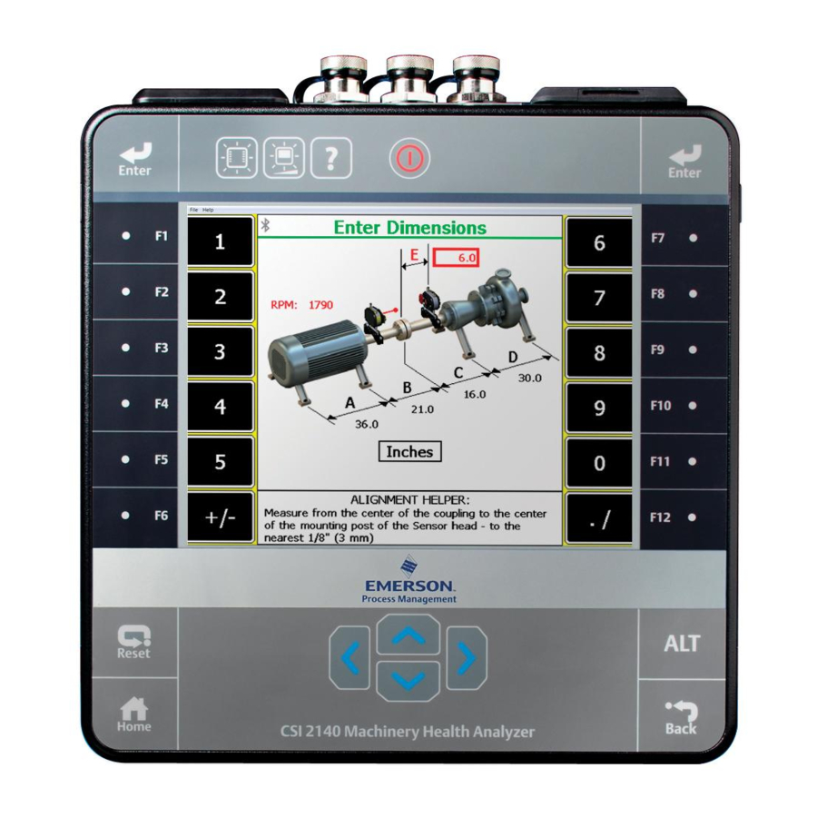
Page 78: Tachometers
Route You can use a tachometer or CSI 430 SpeedVue Sensor to input the RPM. Note If the measurement point is set up for FPM, you are prompted to enter the FPM value rather than the RPM. Procedure Activate a route. From the Route Data Collection screen, press ALT >... - Page 79 Route Option Description F4 Pseudo Shaft (Only available when Pseudo Tach is enabled.) Enter the number of teeth on the internal shaft. The analyzer calculates the pseudo tach frequency based on the number of teeth specified for the tached shaft and pseudo shaft. The default is 1.
-
Page 80: Multiple Inputs And Measurements
Route Press F3 Recall Setup. The setup appears on the Tachometer Setup screen. Press Enter. 4.4.4 Rename a saved tachometer setup From the Route Data Collection screen, press ALT > F5 Tach Setup. From the Tachometer Setup screen, press F6 Save / Recall Setup. Use the up and down arrow keys to select a saved setup. -
Page 81: Collect Route Data
Route Multiple measurements from a single sensor The analyzer can acquire data on measurement points, even when the acquisition parameters are different, using one sensor connected to both inputs. Set up the measurement points as grouped points, the same way as regular dual points, but change the points to use the same input. - Page 82 Route Note The audio is not stored or recorded. Procedure From the Route Data Collection screen, press F9 Listen To Live Data. You can also access Listen To Live Data from a waveform or spectrum plot screen. The Bluetooth Listener screen appears. You are now listening to the vibration signal. Note The Home key is disabled while you are listening to data.
- Page 83 Route The analyzer collects new data. 4.6.3 Skip equipment or points in a route To skip equipment in a route, press F8 Next Equip on the Route Data Collection screen. The equipment listed at the top of the screen changes. To skip a measurement point, press F7 Next Point on the Route Data Collection screen.
-
Page 84: Status Messages
Route 4.6.6 Delete route data from the current measurement point Delete data if you collected data for the wrong measurement point or have bad data. Procedure Activate a route. Ensure the desired measurement point is displayed. From the Route Data Collection screen, press F6 Clear Data. Press Enter. -
Page 85: Notes
Route Option Description For Dual Lower Delta type alarms, the baseline value minus the Alert value Low Alarm 2 was exceeded. For Dual Lower Absolute alarms, the Fault value was exceeded. Measured value is less than the weak side setup but greater than the lowest Low Signal valid signal level for a Dual Upper Absolute and Out of Window Absolute type alarm. - Page 86 Route The new note appears under the User Defined Notes section on the Notes screen. 4.7.2 Delete a note from the analyzer You can delete user-defined notes from your analyzer. Procedure Activate a route. From the Route Data Collection screen, press F4 Notes > F2 User Defined Notes. Press F8 or F9 to select a note.
-
Page 87: Plot Data
Note Emerson recommends collecting route data and marking a frequency on a plot with a cursor before you select an Analysis Expert or measurement in Analyze. When you open Analyze from Route, there are several limitations: •... -
Page 88: View The Measurement Point Setup And History
Route 4.9.1 Open Analyze from a route measurement point Activate a route. Ensure the desired route measurement point is displayed on the Route Data Collection screen. Press F12 Run Analyze. The Analyze menu main appears and lists the route information at the top of the screen. - Page 89 Route Procedure Activate a route. Ensure the desired measurement point is displayed. From the Route Data Collection screen, press ALT > F12 More Point Info > F4 View Trend History. A plot appears. Modify the plot as necessary. Press Enter. 4.10.4 View the sensor setup for a measurement point You can view the sensor parameters for the active route measurement point.
-
Page 90: Route Reports
Route Procedure Activate a route. Ensure the desired measurement point is displayed. From the Route Data Collection screen, press F11 View Parms. A list of parameters appears under the Status field. The background color of the alarm status indicates the severity relative to the alarm level. Press F1 or F7 to move to another measurement point in the route, if necessary. - Page 91 Route Option Description Enter the last point. F3 Ending Point Select the route data to print. F4 Route Data F5 Bar Graph Options Print a bar graph with or without labels. Include or exclude notes. F10 Notes Option Include or exclude spectrum and waveform plots. F11 Plots Option F12 Analyze Data Include or exclude data collected with Analyze.
- Page 92 Route Enter up to 8 characters for a file name. Press Enter. The analyzer begins creating and saving the file to the memory card. The progress is displayed on the screen.
-
Page 93: Chapter 5 Plots
Plots Plots Topics covered in this chapter: • View a full screen version of the plot • Select an active plot • Switch the plot type • Add or remove a cursor • Change the cursor type • Change the scale of the x and y axis •... -
Page 94: Switch The Plot Type
Plots With a plot displayed, press F5 Change Active Plot. A red box surrounds the active plot on the screen. Switch the plot type You can change the type of plot used to display the collected data. The available options vary based on the type of data you collected. -
Page 95: Change The Cursor Type
Plots Change the cursor type You can change the type of cursor to display different types of information on a plot. The types of cursors vary based on the selected plot type. Procedure Plot the data. With a plot displayed, press ALT > F2 Cursor Type. Press F2 Cursor Type until the appropriate cursor type appears. -
Page 96: Expand Or Compress The X Axis
Plots Press the appropriate key to select the x or y axis and enter the new values. Press Enter. Press Enter to return to the plot. Expand or compress the X axis You can zoom in or zoom out of a plot. If a cursor is active, the plot centers on the cursor position. -
Page 97: View Fault Frequencies
Plots The Order selection is only available if Analyze data is collected for a route point setup. After the RPM is set, press the F5 X-Axis Units to toggle from Hz, CPM, and Orders. Procedure Plot the data. Press ALT > F1 Set RPM. 5.10 View fault frequencies Note... - Page 98 Plots...
-
Page 99: Analyze And Advanced Analyze
Analyze and Advanced Analyze Analyze and Advanced Analyze Topics covered in this chapter: • Analyze overview • Manage jobs • Set display parameters • Multi-input measurements • Sensors and inputs • Tachometers • Common data collection parameters • Collecting data using an Analysis Expert •... - Page 100 Analyze and Advanced Analyze Select an Analysis Expert or mode in Manual Analyze to collect the desired type of data. Modify any data collection parameters in Manual Analyze. The data collection parameters vary based on the selected Analysis Expert or Manual Analyze mode. Collect the data.
- Page 101 Analyze and Advanced Analyze Figure 6-1: Analyze main menu The predefined measurements you can run. The F7 More Experts key displays additional measurements. Where the job file is in the analyzer. If the job is on a memory card, "Card" appears. The equipment description.
- Page 102 Analyze and Advanced Analyze Option Description Create, edit, or delete Analyze jobs. This option does not F9 Job Setup appear if you opened Analyze from a route. Detect problems with low-speed equipment, such as below 10 F10 Low Frequency Analysis - SST Determine the turning speed of a shaft.
-
Page 103: Manage Jobs
Analyze and Advanced Analyze Note Advanced Analyze is not available on the single-channel analyzer, but it is standard on the two and four channel analyzers. Manage jobs 6.2.1 Job Setup Job Setup lets you create, edit, and view saved jobs. If you did not open Analyze from a route measurement point and you want to save your data, you must create a job and save the data to it. - Page 104 Analyze and Advanced Analyze To sort the jobs, press ALT > F1 Sort by Alphabet or ALT > F3 Reverse Sort Order. Press F4 Select Job. The Current Job screen displays the job. 6.2.5 Change the job ID From the Analyze main menu, press F9 Job Setup. To switch between internal memory or a memory card, press F1 Change Job >...
- Page 105 Analyze and Advanced Analyze Option Description Enter up to three characters to identify the measurement point for input 1. F2 Edit ID Enter up to three characters to identify the measurement point for input 2. F3 Edit ID F4 Edit ID Enter up to three characters to identify the measurement point for input 3.
-
Page 106: Set Display Parameters
Analyze and Advanced Analyze Select a job and press F4 Select Job. Press F5 Clear Data. The measurement displays "No Data" on the Current Job screen. Press Enter. 6.2.11 Save a job to equipment in a route You can save a job to equipment in a route. When you transfer the job to AMS Machinery Manager, the data is assigned to that equipment in the database. -
Page 107: Multi-Input Measurements
Orbit Plot, let you select any combination of inputs for two input measurements. For Orbit Plots using four inputs, the analyzer uses inputs AB and CD. You can use a triaxial accelerometer, splitter cables, the CSI 2140 Four-Channel Input Adapter, or a combination of them to collect multi-input data. - Page 108 Analyze and Advanced Analyze Option Description Enable or disable data collection on input A. F2 Select/Unselect Input A Enable or disable data collection on input B. F3 Select/Unselect Input B Enable or disable data collection on input C. F4 Select/Unselect Input C F5 Select/Unselect Enable or disable data collection on input D.
-
Page 109: Tachometers
Analyze and Advanced Analyze Option Description Change Sensor Type Select the type of sensor to use for the input. Enter the sensitivity in volts per engineering unit, such as g's for an Change Sensitivity accelerometer. Change Sensor Select ON to use the accelerometer input where the analyzer powers the sensor. - Page 110 Analyze and Advanced Analyze Option Description Enable Pseudo Tach for time synchronous averaging or order tracking F2 Pseudo Tach intermediate shafts in gearboxes that cannot be accessed directly. Use the Pseudo Tach to produce the turning speed signal. The analyzer uses the following formula: (Incoming tachometer frequency) X ((tach frequency X the number of teeth on the tached shaft)/number of teeth on the pseudo shaft).
-
Page 111: Common Data Collection Parameters
Analyze and Advanced Analyze 6.6.3 Open a saved tachometer setup You can open and reuse a setup in any program on the analyzer. Procedure From the Analyze main menu, press F1 Manual Analyze > F7 Tach Setup. From the Tachometer Setup screen, press F6 Save / Recall Setup. Use the up and down arrow keys to select a setup. - Page 112 Analyze and Advanced Analyze from the overall measurement and is normally set at 2 Hz. You can set Fmin to 0, but the minimum value is the second line in the spectrum, where the Fmin value is equal to 2x line resolution.
- Page 113 Analyze and Advanced Analyze Option Description The Force/Exponential window is the default for Impact mode. Impact Force/Exponential testing normally requires two window types. The analyzer applies a Force window to the hammer channel, and an Exponential window to the response channel. The Force/Exponential window automatically applies these window types to the appropriate data.
- Page 114 Analyze and Advanced Analyze Option Description Display the largest amplitude of each spectral line. Use this Peak Hold Average option during a machine coast down or to monitor random fluctuations such as steam whirl or oil whirl. Remove the vibration of other machines from the signal, so Synchronous Time only the vibration from the reference machine remains.
- Page 115 Analyze and Advanced Analyze PeakVue technology lets you find bearing or gear defects earlier than other measurements. PeakVue technology removes normal vibration signals and captures the actual amplitude of high-frequency impacts from bearing or gear defects. Bearing defect frequencies appear in the PeakVue spectrum at their fundamental frequencies and harmonics.
- Page 116 Analyze and Advanced Analyze PeakVue Prefilters Band-pass 20 -150 Hz High-pass 2 kHz Band-pass 50 - 300 Hz High-pass 5 kHz Band-pass 100 - 600 Hz Band-pass 5 - 6.5 kHz Band-pass 500 -1 kHz High-pass 10 kHz High-pass 500 Hz High-pass 20 kHz High-pass 1 kHz Demodulation...
-
Page 117: Collecting Data Using An Analysis Expert
Analyze and Advanced Analyze Option Description Collect data with the once-per-revolution pulse from a tachometer. Use the Set Tach Trigger Percent option to set the percent of waveform to collect before the trigger event. Enter 0 to put the trigger event at the start of the time window. Enter 50 percent to start the trigger in the center of the time window. - Page 118 Analyze and Advanced Analyze Data Collection Note For best results, collect data and mark a frequency in the spectrum before you run an Analysis Expert. The Analysis Expert performs a customized acquisition based on the marked frequency and other point setup information.
- Page 119 Analyze and Advanced Analyze Table 6-1: Uses for Analysis Experts (continued) Symptom or task Recommended Analyze Expert You notice equipment speed varies • Order Tracking. See Section 6.8.15. during data collection and is smearing the spectrum. You want to know the turning •...
- Page 120 Analyze and Advanced Analyze Press Start or Enter to collect the data. Press Enter to view the data. One or more plots display after the data is collected. Press F9 Store Data to save the data to a route or a job, or press F8 Start to redo the measurement.
- Page 121 Analyze and Advanced Analyze Prerequisites • Mount the sensor on a stud or magnet and on a clean, very flat surface with no paint, if possible. Paint absorbs vibration and affects the data accuracy. Due to the short duration of bearing impacts, a higher frequency sensor with the Fmax set between 10,000 and 15,000 Hz works best, even if you measure slow speed machines.
- Page 122 Analyze and Advanced Analyze One or more plots display after the data is collected. Press F9 Store Data to save the data to a route or a job, or press F8 Start to redo the measurement. 6.8.7 Turning Speed Detection Turning Speed Detection confirms the shaft-turning speed frequency based on an estimated speed.
- Page 123 Analyze and Advanced Analyze From the Analyze main menu, press F12 Laser Speed Detection. Press Start or Enter to collect the data. Use the up and down arrow keys to select an estimated speed range. Press Enter. Press Enter to view the data. You can modify the axis and use a cursor to mark a frequency.
- Page 124 Analyze and Advanced Analyze Hammers For the Bump Test Equipment Off and Bump Test Equipment Running, use a regular hammer to hit the machine. Impact mode in Manual Analyze requires an impact hammer. 6.8.10 Bump Test Equipment Off Bump Test Equipment Off lets you check for resonance when the equipment is not running. Use this measurement when high vibration is unexplained.
- Page 125 Analyze and Advanced Analyze Note This is a single-channel measurement. Prerequisites Attach the accelerometer to the analyzer and the equipment. Procedure Create a job or open Analyze from a route measurement point. From the Analyze main menu, press F7 More Experts > F3 Bump Test Equipment Running. Press Start or Enter to collect the data.
- Page 126 Analyze and Advanced Analyze Press Enter to view the data. One or more plots display after the data is collected. Press F9 Store Data to save the data to a route or a job, or press F8 Start to redo the measurement.
- Page 127 Analyze and Advanced Analyze • Enter the correct sensitivity for the clamp, and account for a current transformer (CT) ratio if you measure on a secondary wire. Procedure Create a job or open Analyze from a route measurement point. From the Analyze main menu, press F7 More Experts > F6 Rotor Bar Test Motor Current. Press Start or Enter to collect the data.
- Page 128 Analyze and Advanced Analyze The analyzer averages vibration from other shafts turning at other speeds and vibration from the reference shaft that is not harmonically related to the turning speed. The resulting data is phase locked to the tachometer pulse. Only the turning speed vibration and its integer multiples are left in the spectrum.
- Page 129 Analyze and Advanced Analyze Note Do not use Synchronous Averaging if important data may be filtered. For example, non-synchronous energy could identify a rolling element bearing defect. Recommended parameters 200 Hz Fmax Low Cutoff Lines 400, but limited to 1600 Window Hanning Average Count...
- Page 130 Analyze and Advanced Analyze Press Enter. Press Stop to view the plot. Press F9 Store Data to save the data to a route or a job, or press F8 Start to redo the measurement. Common orbit shapes The orbit shapes indicate machine condition. The list below describes some common shapes and their meaning.
-
Page 131: Collect Data Using Manual Analyze
Analyze and Advanced Analyze Understanding phase shift Phase shift Cause 90 degrees between the vertical and the horizontal directions Imbalance 0 (or 360) degrees across the coupling Imbalance 80 degrees across the coupling Misalignment 0 or 180 degrees between the vertical and the horizontal Resonance directions Amplitude in one direction is greater than 10 times the... - Page 132 Analyze and Advanced Analyze 6.9.1 Collect a waveform A vibration waveform is a graph that shows how the vibration level changes with time. The waveform shows the vibration level at a particular time during the measurement. The waveforms are discrete graphs represented by a series of equally-spaced, discrete sample points (connected by straight lines).
- Page 133 Analyze and Advanced Analyze Press F9 Store Data to save the data to a route or a job, or press F8 Start to redo the measurement. Waveform plots Waveform plots have additional keys on the ALT screen. Enhance Patterns The Enhance Patterns key calculates the Auto Correlation waveform plot from the active waveform plot.
- Page 134 Analyze and Advanced Analyze Figure 6-2: Waveform with Auto Correlation plot set to show RPM lines 6.9.2 Collect a spectrum A spectrum shows all of the frequencies and amplitudes of a machine, within the specified limits of the Fmax and Fmin values. The vibration spectrum is the basic tool for understanding vibration.
- Page 135 AWeight A0760GP is used down to 40 RPM. For frequencies lower than 40 RPM, contact Emerson for a recommendation. Enable F6 Set Aweight to apply a shape curve to the acquired frequency spectrum that approximates the frequency sensitivity of the human ear.
- Page 136 Analyze and Advanced Analyze Set the following options as necessary. Option Description F2 Set Overall Set your Overall acquisition to 1Hz to 80kHz or Fmin to Fmax. 1Hz to 80kHz Mode mode acquires broadband waveform data, and calculates the overall as the RMS value of the waveform.
- Page 137 Analyze and Advanced Analyze Press Enter. The Analyze Setup screen appears. Set the following options as necessary. Option Description Set the center frequency, which is the frequency of interest, the F2 Set Zoom Params resolution in Hz or CPM, and the bandwidth. The Resolution and Bandwidth fields work together.
- Page 138 Analyze and Advanced Analyze Option Description Set the Fmax, Fmin, and lines of resolution. See Section 6.7.1 F2 Set Spectra Params Section 6.7.2. Set the number of spectra to collect, force an RPM measurement, and F3 Set Cascade select the sample type to set how the analyzer collects new data. The Params sample type is not the same as a trigger and takes precedence over a trigger.
- Page 139 Analyze and Advanced Analyze number of skipped spectra, but it also reduces the total range of spectra shown. The plot may remove spectra at the beginning or the end of the plot, and a section of total cascade data display. Use the Page or Scroll keys to change the displayed section of the total cascade.
- Page 140 Analyze and Advanced Analyze Procedure Create a job or open Analyze from a route measurement point. From the Analyze main menu, press F1 Manual Analyze > F1 Set Analyze Mode. Use the up and down arrow keys to select Peak and Phase. Press Enter.
- Page 141 Analyze and Advanced Analyze Press Enter to collect the data. One or more plots display the data. Press F9 Store Data to save the data to a route or a job, or press F8 Start to redo the measurement. 6.9.7 Collect a Filtered Orbit Filtered Orbit lets you analyze the phase relationship between two or four channels at a specific order of turning speed.
- Page 142 Analyze and Advanced Analyze Option Description Select Bandpass or Lowpass. For Bandpass, the analyzer calculates peak and F2 Orbit Mode phase data for both channels using a tachometer input, creates two waveforms, and plots these values in the X (horizontal) and Y (vertical) directions.
- Page 143 Analyze and Advanced Analyze Note When you measure DC Volts, Emerson recommends setting the sensor type as non-standard, a sensitivity of 1.0, Power = OFF, and the coupling mode to DC Coupled. Procedure Create a job or open Analyze from a route measurement point.
- Page 144 Analyze and Advanced Analyze Procedure Create a job or open Analyze from a route measurement point. From the Analyze main menu, press F1 Manual Analyze > F1 Set Analyze Mode. Use the up and down arrow keys to select Temperature. Press Enter.
- Page 145 Analyze and Advanced Analyze Note Cross Channel Phase is not available on the single-channel analyzer. Issue Sensor location Misalignment Measure across a coupling. Looseness/weakness Measure across mechanical interface. Coherence One sensor on each machine. Procedure Create a job. From the Analyze main menu, press F1 Manual Analyze > F1 Set Analyze Mode. Use the up and down arrow keys to select Cross Channel Phase.
- Page 146 Analyze and Advanced Analyze One or more plots display the data. Press F2 Next Response Input to display data for the next response, if you set up more than two inputs. If necessary, press F8 Start to redo the measurement. Note You cannot store the data.
- Page 147 Analyze and Advanced Analyze Press Enter to collect the data. One or more plots display the data. Press F2 Next Response Input to display data for the next response, if you set up more than two inputs. Press F9 Store Data to save the data to a route or a job, or press F8 Start to redo the measurement.
- Page 148 Analyze and Advanced Analyze the recorded frequency is a resonance and no other background vibration. A multi-channel measurement records the amount of force applied with an instrumented impact hammer on one channel and records the response on a second channel. For the Impact test, you can use the triaxial accelerometer and one input for the impact hammer.
- Page 149 Analyze and Advanced Analyze Figure 6-4: Impact waveform with window overlays Run an Impact test Note Impact mode is not available on the single-channel analyzer. Use the Spectra mode or the Bump Test Analysis Experts for the single-channel analyzer. Use the Impact test to measure the relationship between channels. You can use the triaxial accelerometer and one input for the impact hammer.
-
Page 150: Listen To Live Vibration Data In Analyze
Analyze and Advanced Analyze Use the up and down arrow keys to select Impact. Press Enter. The Analyze Setup screen appears. Set the following options as necessary. Option Description F2 Set Spectra Set the Fmax, Fmin, and lines of resolution. See Section 6.7.1 Params Section... - Page 151 Analyze and Advanced Analyze • High Frequency Analysis • High Resolution Analysis • Bearing/Gear Analysis- PeakVue • Low Frequency Analysis - SST • Coast Down Peak Hold • Order Tracking • Synchronous Analysis Note The audio is not stored or recorded. Prerequisites To listen to vibration from an Analysis Expert, you must have the Analysis Experts help text enabled.
-
Page 152: Redo A Measurement
Analyze and Advanced Analyze Option Description Play a test sound to verify the Bluetooth connection to the headphones. F6 Test Headset The analyzer generates a test sound for several seconds. Set the filter for the audio signal. You can select Off (no filter), 2000 Hz High F8 Filter Pass, or 8000 Hz High Pass. -
Page 153: Review Collected Data
Analyze and Advanced Analyze 6.13 Review collected data Review Data shows the most recent data, even if you did not store the data. If you opened Analyze from a route measurement point, you can view only the data saved to the route measurement point. -
Page 154: Reset Analyze Defaults
Analyze and Advanced Analyze Procedure Display your plot in Analyze. You can press F2 Review Data on the Analyze main menu, or collect data and view the plot. Press F7 Print Plot. Enter up to 8 characters for a file name. Press Enter. -
Page 155: Chapter 7 Advanced Transient
Advanced Transient Advanced Transient Topics covered in this chapter: • Advanced Transient overview • Manage jobs • Sensors and inputs • Tachometers • Select a section of the full transient waveform • Set the number and type of plots to display •... - Page 156 Advanced Transient After you collect the data, examine it for any changes in pattern, frequency, or amplitude. The changes reveal how the equipment responds to these transient events or what causes these events to occur. 7.1.2 Open or close the Advanced Transient program To open the program, press F11 Adv.
- Page 157 Advanced Transient Figure 7-1: Transient main menu An alternate (ALT) screen includes additional options. The identifier for the job. The equipment description. Where the job file is in the analyzer. If you saved the job to a memory card, "Card" appears. Available internal memory or memory card.
- Page 158 Advanced Transient Option Description View the collected data. This option is available only if you collected F7 Display Data data for the measurement point. Create and edit jobs, save jobs to another memory location, or F8 Job Manager transfer jobs to AMS Machinery Manager. Intentionally blank.
-
Page 159: Manage Jobs
You use can the four-channel functionality to make your Transient data collection quicker and more efficient. Use the CSI 2140 Four-Channel Input Adapter or two splitter cables to allow you to collect data from four points simultaneously. You can then analyze data for problems, such as oil whirl or resonance. - Page 160 Advanced Transient 7.2.5 Change the equipment description From the Transient main menu, press F8 Job Manager. Use the up and down arrow keys to select a job. Press F4 Edit This Job > F2 Edit Equip Desc. Enter up to 28 characters. Press Enter.
-
Page 161: Sensors And Inputs
Advanced Transient 7.2.9 Activate an Advanced Transient job Activating a job lets you collect data for that job. It is similar to opening a file. Activate a job when you want to change jobs. Procedure From the Transient main menu, press F8 Job Manager. Use the up and down arrow keys to select a job. - Page 162 Advanced Transient The active inputs and units display at the bottom of the screen. Disabled inputs are grayed out. 7.3.2 Set up a sensor You can set sensor parameters for inputs A, B, C, and D. When you use the CSI 0643TX triaxial accelerometer, input A receives measurements from the z-axis, input B receives measurements from the x-axis, and input C receives measurements from the y-axis.
-
Page 163: Tachometers
Advanced Transient Tachometers 7.4.1 Set up a tachometer Note By default, the analyzer is set up to use the CSI 404 tachometers. The analyzer supports tachometer/RPM measurements up to 100,000 RPM. Procedure From the Transient main menu, press ALT > F4 Tach Setup or press F1 Setup / Acquire Data >... - Page 164 Advanced Transient Option Description F12 Set Defaults Restore the default values for all tachometer setup options on the screen. Press F6 Save / Recall Setup to save the setup, or press Enter to use the setup without saving it. 7.4.2 Save a tachometer setup The saved setup is accessible from all other programs on the analyzer.
-
Page 165: Select A Section Of The Full Transient Waveform
Advanced Transient 7.4.5 Delete a saved tachometer setup From the Transient main menu, press ALT > F4 Tach Setup or F1 Setup / Acquire Data > F7 Tach Setup. From the Tachometer Setup screen, press F6 Save / Recall Setup. Use the up and down arrow keys to select a saved setup. - Page 166 Advanced Transient The selections are limited by the number of lines (number of samples divided by 2.56) to collect. The default is 200. Press Enter. 7.5.3 Set the window The window applies a shaping function to the waveform signal before computing the spectrum.
-
Page 167: Set The Number And Type Of Plots To Display
Advanced Transient Procedure Activate a job. From the Transient main menu, press ALT > F5 Data Display Settings > F8 Show Tach. Set the number and type of plots to display Select up to four plots to display transient data. If you want to select fewer than four plots, select an option below and choose the Plot Off option. - Page 168 Advanced Transient 7.7.2 Set the Fmax The Fmax defines the maximum frequency in the spectra. The Fmax setting is not continuous; it is a set of predefined values. The analyzer automatically selects the next higher value. Note If you change the Fmax, the sample time and sample rate also change. Procedure Activate a job.
-
Page 169: Collect Transient Data
Advanced Transient 7.7.4 Enable PeakVue or Demodulation Activate a job. From the Transient main menu, press F1 Setup / Acquire Data > F8 PeakVue Demod. Select the desired option. Press F10 Choose Filter to select a high-pass or band-pass filter. Pre-defined frequency ranges are in the built-in demodulator. -
Page 170: Plot Data
Advanced Transient 7.8.1 Redo a measurement From the Transient main menu, use the up and down arrow keys to select a measurement. Press Enter to select the measurement. Press Enter when prompted to overwrite the existing data. Press F1 Start or Enter. The analyzer collects new data. - Page 171 Advanced Transient From the Transient main menu, select the desired measurement. Press F7 Display Data. 7.9.2 Print a Transient plot to AMS Machinery Manager Prerequisites • On the analyzer, press Home > ALT > F2 General Setup > F6 Set Print Mode and ensure the default print mode is set to Send to PC.
- Page 172 Advanced Transient The analyzer begins creating and saving the file to the memory card. The progress is displayed on the screen.
-
Page 173: Chapter 8 Ods/Modal
™ from Vibration Analysis, and then export the data to ME'scope VES for analysis. The Advanced Cross Channel program is included with all two and four channel CSI 2140 analyzers. To use the ODS/Modal program: Create a job or activate a saved job. You must use a job to save your data. - Page 174 ODS/Modal Collect the data. Transfer the job to AMS Machinery Manager. ™ Export the job to the ME'scope VES for analysis. Note ™ This manual does not describe exporting data to ME'scope VES , or analyzing the data. 8.1.1 When to collect ODS/Modal data Use modal analysis with mechanical equipment and the structural framework, including fans, pumps, compressors, rolling mills, paper machines, or computer components.
- Page 175 ODS/Modal Figure 8-1: ODS/Modal main menu An alternate (ALT) screen includes additional options. The active measurement point (2) and direction (X). The identifier for the job. Where the job file is in the analyzer. If you saved the job to a memory card, "Card" appears. Data collection status.
- Page 176 ODS/Modal Option Description Change the inputs for each direction. This option is available F4 Change Meas Input only when you collected data for the job, and you have 3 or more inputs set up. This is useful if you want to change the orientation of the triaxial accelerometer, or you want to switch from a triax to single sensors.
-
Page 177: Manage Jobs
ODS/Modal Option Description Intentionally blank. Intentionally blank. 8.1.4 Measurement point abbreviations and symbols Measurement points have a number and a three-letter abbreviation to indicate the direction. Note ™ ME'scope VES uses X, Y, Z. • X, Y, Z: rectangular • R, T, Z: cylindrical •... - Page 178 ODS/Modal 8.2.2 View all saved ODS/Modal jobs From the ODS/Modal main menu, press F8 Job Manager. All the saved jobs display. To sort the jobs, press ALT > F1 Sort by Alphabet or ALT > F3 Reverse Sort Order. 8.2.3 Create an ODS/Modal job When you create a job, you must set up the measurement parameters and the fixed reference parameters.
-
Page 179: Sensors And Inputs
ODS/Modal Use the up and down arrow keys to select a job. Press F4 Edit This Job > F2 Edit Equip Desc. Enter up to 28 characters. Press Enter. 8.2.6 Activate an ODS/Modal job Activating a job lets you collect data for that job. It is similar to opening a file. Activate a job when you want to change jobs. - Page 180 ODS/Modal Procedure From the ODS/Modal main menu, press F8 Job Manager > F4 Edit This Job > F12 Input Setup > F1 Select Input. Note After you collect data, the F12 Input Setup key is no longer available. Select one or more inputs. Option Description Enable or disable data collection on input A.
-
Page 181: Tachometers
ODS/Modal If you collected data for the job, the F12 key on the Edit Job Setup menu becomes the Sensor Setup option. You cannot change the number of inputs after you collect data, but you can change the sensor type. You can also set up a sensor from the ODS/Modal ALT2 main menu. - Page 182 ODS/Modal Procedure From the ODS/Modal main menu, press ALT > F4 Tach Setup. The Tachometer Setup screen appears. You can also open the Tach Setup option by pressing F8 Job Manager > F4 Edit This Job > F8 Analysis Setup > F7 Tach Setup. Set the following options as necessary.
- Page 183 ODS/Modal Procedure From the ODS/Modal main menu, press ALT > F4 Tach Setup. The Tachometer Setup screen appears. You can also open the Tach Setup option by pressing F8 Job Manager > F4 Edit This Job > F8 Analysis Setup > F7 Tach Setup. From the Tachometer Setup screen, press F6 Save / Recall Setup.
-
Page 184: Set Up The Plots
ODS/Modal The Tachometer Setup screen appears. You can also open the Tach Setup option by pressing F8 Job Manager > F4 Edit This Job > F8 Analysis Setup > F7 Tach Setup. From the Tachometer Setup screen, press F6 Save / Recall Setup. Use the up and down arrow keys to select a saved setup. -
Page 185: Set Up The Job
ODS/Modal Option Description Display the spectrum from the response input. Spectrum - Response Describe the degree of linear relationship between the reference Coherence and response inputs. A coherence value close to one (1.0) at a frequency indicates the response and reference are linearly related, and the measurement signal to noise ratio is high. - Page 186 ODS/Modal Option Description Use the up and down arrow keys to select Rectangular (X, Y, Z), Cylindrical F4 Set Coordinate (Radial, Theta, Axial), or Spherical (Radial, Theta, Phi). The default is (X, Y, Z). Note ™ ME'scope VES uses X, Y, Z. F5 Set Meas Use the up and down arrow keys to select the direction.
- Page 187 ODS/Modal Option Description F2 Set Spectra Params Set the Fmax, Fmin, and lines of resolution. See Section 6.7.1 Section 6.7.2. Set the type of averaging, the number of averages to collect, and the F3 Set Averaging acquisition mode. See Section 6.7.4.
- Page 188 ODS/Modal Press F4 Edit Setup Desc. Enter up to 20 characters for a name. Press Enter. Reset the acquisition parameters to default values From the ODS/Modal main menu, press F8 Job Manager. Press F4 Edit This Job > F8 Analysis Setup > F6 Save / Recall Setup. Press F5 Recall Default Setup.
-
Page 189: Collect Ods/Modal Data
ODS/Modal Option Description Set the direction for a measurement. The direction is usually determined F12 Set Fixed Ref Polarity by the construction of the equipment. If you cannot place the sensor in the positive direction, specify a negative direction. The default is Positive. Press Enter. - Page 190 ODS/Modal Connect the sensor to the analyzer and equipment to measure. From the ODS/Modal main menu, use the up and down arrow keys to select a measurement point. Press F2 XYZ to select a measurement direction for the point. The directions that are collected together are highlighted red. Press F1 Start.
- Page 191 ODS/Modal Procedure Activate a job. From the ODS/Modal main menu, do one of the following: • Use the arrows on the keypad to select a different measurement point. • Press F9 Point Search and enter the desired measurement point, ignoring the zeroes at the beginning of the number.
-
Page 192: Display The Data For A Measurement Point
ODS/Modal 8.7.5 Redo a measurement You can store one set of data per measurement point/direction. However, you can overwrite a measurement. Procedure From the ODS/Modal main menu, press F9 Point Search or use the arrows on the keypad to go to a measurement point. Press Enter to collect data. -
Page 193: Print An Ods/Modal Plot To A Memory Card
ODS/Modal • Ensure the same connection type is set on the analyzer and in Data Transfer. The Ethernet and Wireless options may require additional setup to connect to the desired computer. See the Ethernet and Wireless sections and your IT group for more information. - Page 194 ODS/Modal...
-
Page 195: Chapter 9 Balance
Balance Balance Topics covered in this chapter: • Balance overview • Manage jobs • Job Setup • Sensor Setup • Measurement Plane Setup • Weight Plane Setup • Acquire Data • Balance correction • Trim run • One-run balance job •... - Page 196 Balance Set up the job parameters, including balance mode, balance specification, speeds, tachometers, sensors, measurement planes, measurement points, and weight planes. Acquire runout (optional), reference run, and trial run data to calculate the balance correction. View the calculated balance correction. Acquire trim runs to ensure the machine is within the balance specification based on your site or the machine manufacturer.
- Page 197 Balance Figure 9-1: Balance main menu Displays an X for each completed step in the balance procedure. The steps are Job Setup, Acquire Data, View Corr, and Trim Run. The identifier for the job. The equipment description. Number of completed trim runs. Number of attached notes.
- Page 198 Balance Option Description Acquire trim runs to ensure the machine is within the balance F6 Trim Run specification based on your site or the machine manufacturer. Close Balance and return to the Home screen. F7 Exit Balance Intentionally blank. Intentionally blank. Intentionally blank.
- Page 199 Balance 9.1.3 Single-plane balance job overview A new single-plane job has the following steps: Create a new job or activate an existing job. Set up the job parameters. (Optional) Acquire runout data. Acquire reference run (as-is) data. Add or remove trial weights. Acquire trial run data.
-
Page 200: Manage Jobs
Balance A balance weight added to one end affects the vibration levels at both ends. The primary effect is the balance weight on the nearest support bearing. Cross effect is the effect of the balance weight on the opposite support bearing. Multiple plane balancing takes into account both primary and cross effect when calculating corrections. - Page 201 Balance Press Enter. 9.2.4 Edit the job description You can change the default or saved IDs and descriptions for a job. By default, each job is given a unique Job ID. A Job ID is required. Other options are optional and are printed on reports from UltraMgr.
- Page 202 Balance 9.2.6 Copy a Balance job Create a copy of a job in the same memory location. The new copy is highlighted, but not activated. You must activate the job. If you want to copy or move the job from internal memory to a memory card, use the File Utility on the Home screen.
-
Page 203: Job Setup
Balance Job Setup After you create or activate a job, set up or review the parameters in Job Setup. An X appears next to Job Setup on the Balance main menu when you complete this step. Depending on the Balance mode, one or three screens are required to setup the job parameters. - Page 204 Balance • You cannot view the reference run data or last set of trim run data from the trial run. Change the mode You can change the mode for a job at any time. When you change the mode, the setup parameters reset to their default values and any data stored in the job is deleted.
- Page 205 Balance Option Description Enter a number between 1 and 8 and press Enter. The maximum number F3 Meas. Points depends on the number of measurement planes. Enter a value between 0.001 and 10,000 for the desired vibration level for F8 Enter Balance the equipment, and press Enter.
- Page 206 Balance Option Description Repeatedly press F2 until the 2 planes, 2 sensors option appears. F2 Toggle Config. Enter a value between 0.001 and 10,000 for the desired vibration F8 Enter Balance level for the equipment, and press Enter. The units are the same as the Spec.
- Page 207 Balance Postrequisites In Advanced Balance mode, set up the measurement plane. See Section 9.5. 9.3.4 Tachometers Set up a tachometer By default, the analyzer is setup for CSI 404 tachometers. Pseudo Tach must be disabled for the Balance program. When the pseudo tach is disabled, a standard 1x tach is produced.
- Page 208 Balance Save a tachometer setup The saved setup is accessible from all other programs on the analyzer. Procedure From the Balance main menu, press F3 Job Setup > F10 Tach Config > F6 Tach Setup. From the Tachometer Setup screen, press F6 Save / Recall Setup. Use the up and down arrow keys to select Empty or another tachometer setup.
- Page 209 Balance Set the tachometer angle The tachometer location identifies the tachometer reference pulse for future setup, on graphs, and in some special calculations performed in Calculator Mode. The location is indicated by a “T”. The analyzer does not use tachometer location to calculate the balance correction.
-
Page 210: Sensor Setup
Balance Note This is available only in Advanced Balance mode. Procedure From the Balance main menu, press F3 Job Setup > F11 Speed Setup. Set the following options as necessary. Option Description F3 Delta RPM Enter a number between 0 and 500 to set the valid running speed range for all speeds. - Page 211 Balance If you define two measurement points, 90 degrees apart, for each measurement plane, you can see if both axes react similarly. Occasionally, equipment does not react symmetrically due to a significant difference in constraint between axes or resonance. Note You can define up to three sensors for each measurement plane.
- Page 212 Press Enter. 9.4.4 Channels and measurement points If the CSI 2140 Four-Channel Input Adapter is enabled, define one channel for each measurement point. For example, assign input A to measurement point 1 (IBH) and channel B to measurement point 2 (IBV).
- Page 213 Balance Option Description The analyzer does not use the CSI 2140 Four-Channel Input Adapter or external multiplexer. The analyzer acquires all data through the same channel, and you must manually start and accept each measurement. The CSI 2140 Four-Channel Input Adapter controls software that switches between channels.
-
Page 214: Measurement Plane Setup
Balance 9.4.7 Enable or disable the runout measurement Runout is an optional measurement acquired using a displacement sensor during a slow roll of the rotor. A slow roll means the rotor rotates so slowly that readings from the sensors only detect mechanical irregularities on the rotor surface, not vibration. Use runout data to help normalize the balance data. - Page 215 Balance 9.5.1 Measurement points A measurement point is where you collect a measurement on the equipment. You must define at least one measurement point. The default setup distributes the points equally among the defined measurement planes. For example, if you set up seven points and three planes, plane 1 has three points, plane 2 has two points, and plane 3 has two points.
- Page 216 Balance 9.5.2 Add a measurement point to a measurement plane You can add up to three measurement points for a measurement plane. The points are added at the end of the list. Note This is available only in Advanced Balance mode. Procedure From the Balance main menu, press F3 Job Setup.
-
Page 217: Weight Plane Setup
Balance 9.5.4 Set up the measurement points on measurement planes From the Balance main menu, press F3 Job Setup. Press Enter or F4 Meas Plane Setup. The Measurement Plane Setup screen appears. Ensure the correct measurement plane is displayed at the top of the screen. Press Enter to go to the next plane, if necessary. - Page 218 Balance Where to place the weights - discrete or continuous A weight plane is discrete or continuous. Discrete weight planes let you place weights only at a specific, numbered positions. Continuous weight planes let you place weights at any position on the rotor, and do not display numbered positions. You can define both types in the same job.
- Page 219 Balance Note After you collect trial run data, you cannot change the weight locations. Procedure From the Balance main menu, press F3 Job Setup. Press F5 Weight Plane Setup or Enter until the Weight Plane Setup screen appears. Press F8 Toggle Discrete Contin to select Continuous or Discrete. Continuous weight planes let you place weights anywhere, and discrete weight planes let you set weights only at specified locations on the plane.
-
Page 220: Acquire Data
Balance 9.6.3 Set the weight plane radius You can set the trial and trim weight placement radius. Weight plane radius ensures you use the same radius in the job. Use this option as a reference and for future setups only. This setting is optional. - Page 221 Balance Figure 9-3: Example of graphs and information displayed Vibration compared to the balance specification (the circle). X appears within the circle when vibration is within the balance specification. A cross hair (+) symbol indicates the endpoint of the averaged phase/ magnitude vector. A vector line with a terminating square symbol on one end indicates the instantaneous vector.
- Page 222 Balance Option Description Zoom out on the image. F3 Decrease Scale Change the direction of the shaft rotation for the current F4 Toggle Direction Rotation diagram. Intentionally blank. F6 Accept Data Save the collected data to the job. Intentionally blank. F8 Clear Data Clear the averaged magnitude and phase data.
- Page 223 Attach one or more displacement sensors to the analyzer. • If you use more than one sensor and do not use the CSI 2140 Four-Channel Input Adapter, ensure you connected the proper cables before collecting data. Collect the measurement for the appropriate input.
- Page 224 • Ensure the machine is running. • If you use more than one sensor and do not use the CSI 2140 Four-Channel Input Adapter, ensure you connected the proper cables before collecting data. Collect the measurement for the appropriate input.
- Page 225 You may want to acquire a frequency signature at the points to determine the other frequencies and consider other possible causes. Emerson recommends you use the same vibration units (acceleration, velocity, or displacement). Changing units can dramatically change the apparent distribution of energy.
- Page 226 Balance Ratio Status Greater than 8:1 High Ratio alert is triggered for two sensors close to Resonance Likely 90° apart, and the phase change is approximately 0° or 180° Axial 1xRPM vibration is greater than radial Note This is available only in Advanced Balance mode. Imbalance usually causes higher radial vibration magnitudes at rotational frequency than axial magnitudes.
- Page 227 Balance Enter the weight and location of the trial weight into the Estimate Trial Weights screen. Start the equipment. Acquire data at all measurement points and speeds. Repeat these steps for each trial run in your job. Where to place the trial weights Trial weights determine the effect on the equipment when you add or remove a known weight at a known location.
- Page 228 Balance • If you use more than one sensor and do not use the CSI 2140 Four-Channel Input Adapter, ensure you connected the proper cables before collecting data. Collect the measurement for the appropriate input. Procedure From the Balance main menu, press F4 Acquire Data > Acquire Trial Run Data for the appropriate trial run.
- Page 229 Balance Collect data until the magnitude is stable and phase varies by no more than 5 degrees in the Data Stability graph. Press Accept Data to save the data. If you selected Auto for the mux option, the Balance program automatically accepts the data and moves to the next point when the phase and magnitude are good for 3 consecutive averages.
-
Page 230: Balance Correction
Balance The analyzer collects new data. 9.7.6 Clear all measurements for a job The Clear Job Data option lets you delete all collected data for a job. The job setup parameters are not deleted. Note Use caution with the Clear Job Data option. Deleted data cannot be recovered. Procedure From the Balance main menu, press ALT >... - Page 231 Balance Procedure From the Balance main menu, press F5 View Corr. Review the correction and verify the accuracy of the information. Each weight and location on the weight plane is color-coded and matches the graph at the bottom of the screen. Figure 9-5: Balance correction example - Advanced Balance mode Press Leave Trial Wt.
-
Page 232: Trim Run
Balance Trim run After you view the balance correction, acquire trim run data to get the vibration within the balance specification you set in Job Setup. After a trim run is complete, the trim correction displays. The trim run has the following steps: Install the correction weight. - Page 233 Attach one or more vibration sensors and the tachometer to the analyzer. • If you use more than one sensor and do not use the CSI 2140 Four-Channel Input Adapter, ensure you connected the proper cables before collecting data. Collect the measurement for the appropriate input.
- Page 234 Balance Collect data until the magnitude is stable and phase varies by no more than 5 degrees in the Data Stability graph. Press Accept Data. Repeat the steps above for all measurement points for all trim runs. If you select Auto for the mux option, the Balance program automatically accepts the data and moves to the next point when the phase and magnitude are good for 3 consecutive averages.
- Page 235 Balance • Lines connecting the reference run reading and up to two additional trim readings, always using the last two trim run readings, for each measurement point defined for the plane. • % Down (percent of magnitude change) - Relationship between the most recent trim run reading and the initial reading.
-
Page 236: One-Run Balance Job
Balance 9.10 One-run balance job A one-run balance job, also called trim balancing, lets you use a balance job and its reference run, trial run, and balance correction to balance the same or similar equipment. After equipment is successfully balanced, transfer the balance job to AMS Machinery Manager for storage. -
Page 237: Notes
Balance 9.11 Notes Notes let you make comments and observations about the equipment you are monitoring. After you add the note to the job, it is saved with your measurement data. When you transfer the job to AMS Machinery Manager, the note is included. The analyzer has pre-defined notes you can use. -
Page 238: Balance Summary Reports
Balance 9.11.3 Remove a note from a job From the Balance main menu, press ALT > F3 Notes. Under Assigned Notes, use the up and down arrow buttons to select a note to delete. Press F5 Remove From Job. The note is removed from the Assigned Notes section and your job. To remove all notes, press F6 Clear All Notes. - Page 239 Balance Figure 9-7: Summary report example Option Description Job ID set in Job Desc. Job Number Data Taken Date and time you collected the data. User ID set in Job Desc. Technician Notes you attached to the job. Notes Shaft Number Number of shafts defined in Job Desc.
- Page 240 Balance 9.12.1 Print a balance summary report to AMS Machinery Manager Prerequisites • On the analyzer, press Home > ALT > F2 General Setup > F6 Set Print Mode and ensure the default print mode is set to Send to PC. •...
-
Page 241: Review Balance Data
Balance 9.13 Review balance data You can view the data collected or manually entered for any of the measurement runs in a job. You cannot edit these values from the Review Data screen. Procedure From the Balance main menu, press ALT > F9 Review/Edit Data. The measurement run appears at the top of the screen. -
Page 242: Manually Enter Balance Job Data
Balance 9.14 Manually enter balance job data You can manually enter or edit speed, magnitude, and phase information for a measurement in a job. Modify values to review additional scenarios or enter data you did not collect. The required measurements are displayed with the first measurement point highlighted. - Page 243 Balance Calculator Mode Recommended use Calculate a correction that combines several weights on the rotor into one Sum Weights weight. See Section 9.15.2. The available balance weights do not match the balance or trim correction. Adjust Fixed Weights Section 9.15.3. Calculate the weight locations to address the static and couple Static/Couple Analysis components of the imbalance.
- Page 244 Balance Calculator Mode Recommended use Calculate a value in units of acceleration, velocity, and displacement. Units Conv Note This is available only in Advanced Balance mode. Section 9.15.9. 9.15.1 Determine another location to place weights The Split Angle option lets you calculate a new location for the weights if you cannot place them at the location specified in the balance correction.
- Page 245 Balance If you opened Split Angle from a trim run, press F12 Insert to Trim Weight to send the calculated solution to the Trim Run Applied Weight entry screen. Press F7 Split Angle Calc. to exit and return to the calculation screen. 9.15.2 Combine multiple weights on a rotor The Sum Weights option lets you enter up to three known or desired weights and angular...
- Page 246 Balance Procedure From the Balance main menu, press ALT > F6 Calculator Mode > F4 Adjust Fixed Weights. Set the following options as necessary. Option Description F2 View Balance View the last calculated balance correction. This option displays only if the Corr.
- Page 247 Balance Note When the job has discrete weight positions and you import from the Balance Correction screen, the analyzer converts the discrete positions to continuous positions. Procedure From the Balance main menu, press ALT > F6 Calculator Mode > F5 Static Couple Analysis. Set the following options as necessary.
- Page 248 Enter the sensor/phase lag in degrees introduced by the sensor. For F6 Enter Sensor Emerson supplied accelerometers, sensor lag is normally 0 degrees. The default is 0. Enter the measurement points to use. You can average all readings in a...
- Page 249 Balance Option Description Enter the effect of the mechanical amplification on the vibration F11 Enter Amp. Factor magnitude resulting from an amount of imbalance. Enter a unitless value between 0.0001 and 20.000. The default is 3. Note Amplification factors increase as the rotational frequency moves closer to the critical frequency.
- Page 250 Balance Option Description View the last calculated balance correction. This option displays only if F2 View Balance Corr. the analyzer calculated a balance correction and you accessed Circumference Conversion from the Trim Run Applied Weight menu. Enter the desired angle in degrees, typically the calculated correction F3 Enter Desired Angle angle, or import it from the balance correction.
- Page 251 Balance Option Description Enter the desired weight between 0.00 and 10,000, typically the F3 Enter Known Weight calculated correction weight, or import it from the Balance Correction screen. The default is 0. You cannot import discrete positions. This field is unitless.
- Page 252 Balance Option Description Select the weight plane to use. You may want to select the plane F3 Select Weight Plane nearest the measurement plane that has the readings you want to use. The default is weight plane 1. Enter the weight of the rotor between 0.00 and 100,000 lbs or 0.00 F4 Enter Rotor Weight and 45,454.54 kg.
-
Page 253: Tips And Additional Information
Balance Procedure From the Balance main menu, press ALT > F6 Calculator Mode > F11 Units Conv. Enter the values and the units you want to convert. Option Description F2 Enter Mag. Enter the magnitude of the vibration units to convert. Enter a value between 0.00 and 100,000. - Page 254 Balance Key concepts for balancing machines • Imbalance causes vibration to occur at the rotational frequency (1xRPM) of the imbalanced rotor. • The vibration is directly proportional to the amount of imbalance. Doubling the amount of the imbalance doubles the amount or magnitude of the vibration. •...
- Page 255 Use the CSI 2140 Four-Channel Input Adapter to avoid switching cables or moving sensors between measurement points Use the CSI 2140 Four-Channel Input Adapter or two splitter-Y cables and four sensors to eliminate the need to switch or move sensors on most balancing jobs.
- Page 256 Balance Store every balance job for later reference Use AMS Machinery Manager Data Transfer to transfer the job from the analyzer to the database. Save jobs to reduce setup time when you need to balance the equipment again. The necessary setup and dynamic data for one-run balancing are already available, which reduces the time you spend balancing the equipment.
- Page 257 Balance 9.16.4 Identify the correction planes You can balance a rotor system exactly in N+2 planes (where N = the number of shaft criticals below operating speed). Most mechanical systems are designed to operate below their first shaft critical, so use 0 + 2 = 2 planes. Virtually all systems operate below their fourth critical, so use 3 + 2 = 5 planes.
-
Page 258: Balance Accessories
Balance Issue Potential solution The measured amplification The cause may be a rotational frequency close to a resonance that is factor is greater than six. amplifying the vibration. Check the resonant frequencies. Slight changes in weight size and location cause dramatic changes in the apparent degree of imbalance. - Page 259 Use the selected scale for all readings. Degree scaling correlates directly to the Emerson convention of measuring angles and phase in degrees counter to rotation.
- Page 260 Balance Place the Balancing Compass on an axial face with the indicator needle pointing at 0 degrees. Figure 9-9: Attach and zero Turn the rotor until the indicator reads the desired angular position from the applicable scale. This position is now aligned with the stationary reference. Figure 9-10: Turn the rotor Determine the position of a sensor or tachometer pick up...
- Page 261 Balance Attach the Balancing Compass to any axial face of the rotor so you can see it throughout one rotation. This includes the end of the shaft, the axial face of the rotor itself, or the axial face of anything attached to the shaft, such as a sheave or coupling.
- Page 262 Balance Double scale 0-360° clockwise 0-360° counter clockwise Magnetic backing Requires vertical orientation on axial face of the shaft or rotor 9.17.2 Clamp-on reusable trial weights The CSI Model 8BA20 Trial Weights Assortment includes nine reusable clamp-on trial weights. Weights are clamped on by using knurled cup point set screws in combination with cone point set screws on the opposing side.
- Page 263 Balance Note As a practical matter of safety, Emerson recommends using trial weights that are securely bolted or welded to the rotor being balanced. Emerson does not warrant the applicability or safety of using any weight glued or clamped onto a rotor, including those contained in this kit.
- Page 264 Balance As would be expected, both the 2nd and 3rd configurations proved to hold considerably better than having set screws on only one side. The 3rd configuration usually resulted in some performance improvement over the 2nd configuration however, it gave less consistent results (probably due to the difficulty in getting all the set screws torqued uniformly).
- Page 265 Balance Figure 9-15: Series A...
- Page 266 Balance Figure 9-16: Series B...
- Page 267 Balance Figure 9-17: Series C 9.17.3 Approximate hardware weights The information below lists calculated weights of both coarse thread (UNC) and fine thread (UNF) bolts. This is very useful in any balancing procedure when you use bolts to add balance weight. Weights are calculated for the following bolt hardware: •...
- Page 268 Balance Material Process Stainless steel Multiply weight by .9880 Aluminum Multiply weight by .3442 Brass Multiply weight by 1.0766 To convert ounces to grams, multiply the weight in ounces by 28.3495.
-
Page 269: Appendix A Technical Specifications
Technical specifications Appendix A Technical specifications Topics covered in this appendix: • Hardware specifications • Measurement specifications • Input specifications • Connecting to a computer • Waste Electrical and Electronic Equipment Hardware specifications Physical dimensions Dimensions 8.8" (248 mm) high, 1.57" (40 mm) deep, 8.9" (226 mm) wide Weight 3.95 lbs (1.79 kg) LCD display... -
Page 270: Measurement Specifications
Technical specifications Battery pack Recharge time 4 hours (Nominal) Charging temperature 50° to 95° F (10° to 35° C) Measurement specifications Frequency analysis A/D converter 24 bits of precision Automatic Integrator Correction Allows precise measurement of low frequency vibrations down to 0.2 Hz Averaging modes Normal, Exponential, Peak Hold, Order Tracking, Negative Averaging, Synchronous Time... -
Page 271: Input Specifications
Technical specifications Input specifications Input signals A 2-milliampere, 20-volt (nominal), constant-current power supply inside the analyzer powers sensors, such as accelerometers, connected to the accelerometer channel inputs. Full scale input level Accel channels A, B, C, D Volts channels A, B, C, D Accelerometer input 0-20 V Full scale vibration level is +/- 90 g's when using a 100-mV/g accelerometer Volts input... -
Page 272: Connecting To A Computer
Technical specifications Input unit types Vibration Signals Units Acceleration g’s Velocity In/sec or mm/sec Displacement Mils or microns Other dynamic Any user-specified unit signals DC Signals Any user-specified unit Tachometer input RPM range 1 to 100,000 RPM Tach input level TTL input, built-in conditioning for non-TTL signals, adjustable trigger level. -
Page 273: Waste Electrical And Electronic Equipment
Technical specifications Waste Electrical and Electronic Equipment Marking for the Waste of Electrical and Electronic Equipment in accordance with Article II (2) of Directive 2002/96/EC (WEEE). The European Directive 2002/96/EC requires marking: • That applies to electrical and electronic equipment falling under Annex IA of Directive 2002/96/EC. - Page 274 Technical specifications...
-
Page 275: Glossary
Glossary Glossary a-weighting A frequency shaping method that can be applied to a spectra based upon the frequency response of the human ear. The resulting spectra represents the loudness of the various levels as they would appear to the human ear. alarm An indication that the parameters of a machine have changed in a significant manner. - Page 276 Glossary Data Transfer An application within AMS Machinery Manager that facilitates the transfer of data in the form of a route or job between the AMS Machinery Manager database and analyzers. data units The units that are used to display the measured data. The analyzer can display data in the sensor's units (no conversion), or vibration sensor units can be converted to acceleration, velocity, or displacement.
- Page 277 Glossary high spot The location of the rotor where peak vibration occurs in response to the heavy spot. Heavy spot differs from high spot due to system lag. high-frequency The amplitude of vibration in g's over a broad frequency band from 5 kHz up to 20 detection, HFD kHz or greater.
- Page 278 Glossary plane Designates one or more of the rotating elements of a piece of equipment that is to be balanced. Each plane lies perpendicular to the line that defines the axis of rotation. predictive Technology of periodically monitoring the actual condition of equipment to maintenance discover faults, to determine probable time of breakdown, and to provide scheduled downtime for repair that avoids excess cost and lost production.
- Page 279 Glossary trial weight Weight placed on the rotor to determine the effect of altering mass at a specific location. trigger Causes the analyzer to start collecting data upon the receipt of a specified dynamic signal from a sensor. trim correction Balance correction based on influence coefficients from previous reference and trial runs.
- Page 280 Glossary...
-
Page 281: Index
Index Index correction discrete weight locations 211, 212 Accel connectors dump a job Adjust Fixed Weights jobs 194–196 Adjust Radius load job Advanced Cross Channel main menu 190–192 ALT screens 14–16, 19 manually enter data Amplification Factor measurement point angle AMS Machinery Manager Data Transfer measurement point channel AMS Machinery Manager Standalone Data Transfer... - Page 282 211, 212 four-channel create cover page connections Cross Channel Amplitude/Phase impact test Cross Channel Phase input adapter 32, 33 CSI 2140 Four-Channel Input Adapter 32, 33 ODS/Modal CSI 430 SpeedVue sensor route 74, 75 cursor Transient add or remove Four-Channel Input Adapter...
- Page 283 Index group number LCD backlight analyzer automatically turn off 14–16 in route 74, 75 group status timer set intensity group summary timer Route LEDs 6, 12, 14, 21 lines of resolution listen to live data 75, 144 load Balance job Hanning window load MRL hard reboot...
- Page 284 Index notes select active plot add to job view fault frequency add to route measurement point view full screen create view peaks 79, 231 delete from analyzer point advance 80, 232 delete from job power key delete from measurement point overview set hold time standby...
- Page 285 Index listen to live data display in ODS/Modal load into analyzer display in route report 84, 85 load using MRL display route data 66, 68 move to another memory location lines of resolution multiple inputs overlap 74, 75 68, 100 overview plot in Route plot data...
- Page 286 Index group status standby connect to AMS Machinery Manager tolerance check for trim run overview touchscreen port calibrate set connection type gestures lock lock when carrying Volts/Tach connector overview Transient collect data dump a job warning alarms jobs watchdog checks 153–155, 164 219, 220, 223 main menu...
- Page 287 Index change type expand or compress Y axis change scale change type...
- Page 288 2013, Emerson Process Management Machinery Health Management All rights reserved. The Emerson logo is a trademark and service 835 Innovation Drive mark of Emerson Electric Co. All other marks are property of their Knoxville, TN 37932 USA respective owners. T +1 865-675-2400...
Need help?
Do you have a question about the CSI 2140 and is the answer not in the manual?
Questions and answers