Sign In
Upload
Manuals
Brands
Emerson Manuals
Measuring Instruments
HASX2E-IM-HS
Emerson HASX2E-IM-HS Manuals
Manuals and User Guides for Emerson HASX2E-IM-HS. We have
1
Emerson HASX2E-IM-HS manual available for free PDF download: Instruction Manual
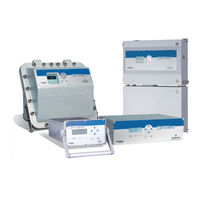
Emerson HASX2E-IM-HS Instruction Manual (436 pages)
Gas Analyzers
Brand:
Emerson
| Category:
Measuring Instruments
| Size: 38 MB
Table of Contents
Table of Contents
4
Definitions
13
Introduction
13
Terms Used in this Instruction Manual
14
Symbols Used on and Inside the Unit
15
Symbols Used in this Manual
16
General Safety Notice / Residual Risk
17
Intended Use Statement
17
Safety Instructions
17
Additional Literature
18
Authorized Personnel
18
Installing and Connecting the Unit
19
Operating and Maintaining this Unit
19
Chapter 1 Technical Description
25
Overview
27
The Front Panel
27
Fig. 1-1: X-STREAM Front Panel (here the X-STREAM X2GP)
27
Configuration of Gas Lines
28
Materials Used
28
Safety Filter
28
Inlets and Outlets
28
Pipework
28
Infallible Containments
28
Optional Components for Gas Lines
29
Fig. 1-2: Optional Heated Area
31
Configurations
32
Fig. 1-3: Gas Flow Diagram: Single Channel or in Series
32
Interfaces
33
Analog Outputs
33
Status Relays
33
Optional Interfaces
34
Fig. 1-4: Serial Interface Marking
34
Comparison of the Various X-STREAM X2 Analyzer Models
36
X-STREAM X2GK: ½19 Inch Table-Top Unit
38
Fig. 1-5: X-STREAM X2GK - Views
40
X-STREAM X2GP: 19 Inch Table-Top or Rackmount Design
41
Fig. 1-6: X-STREAM X2GP - Views
43
Fig. 8-1: X-STREAM X2GP
43
X-STREAM X2XF: Field Housing with (XLF) Single or (XXF) Dual Compartment
44
Fig. 1-7: X-STREAM X2XF Field Housings - Front Views
46
Fig. 1-8: X-STREAM X2XF Field Housings - Front Panel
47
Fig. 1-9: X-STREAM XLF - Bottom and Side View
48
Fig. 1-10: X-STREAM XLF - Power Supply and Signal Terminals
49
Field Housing for Installation in Hazardous Areas (Ex-Zones / Divisons)
50
X-STREAM X2FD: Cast Aluminum Flameproof Housing
51
Fig. 1-11: X-STREAM X2FD - Front View
53
Fig. 1-12: X-STREAM X2FD - Front Panel
54
Fig. 1-13: X-STREAM X2FD - Bottom View
54
Fig. 1-14: X-STREAM X2FD - Terminals
55
Chapter 2 Technical Data
57
Common Technical Data
60
Model-Specific Technical Data
61
X-STREAM X2GK: ½19 Inch Table-Top Unit
61
Fig. 2-1: X-STREAM X2GK - Dimensions
61
Fig. 2-2: X-STREAM X2GK - Rear Panel and Handle Variations
62
Fig. 2-3: UPS 01 T Power Supply Unit
65
Fig. 2-4: 10 a Table-Top PSU
66
X-STREAM X2GP: 19 Inch Table-Top and Rack-Mount Models
68
Fig. 2-5: X-STREAM X2GP - Dimensions
68
Fig. 2-6: X-STREAM X2GP - Power Supply and Signal Connections
70
Fig. 2-7: X-STREAM X2GP - Signal Connections with Screw-Type Terminal Adapters
70
X-STREAM X2XF: Single (XLF) or Dual (XXF) Compartment Field Housing
71
Fig. 2-8: X-STREAM XLF - Dimensions
71
Fig. 2-9: X-STREAM XXF - Dimensions
72
Fig. 2-10: X-STREAM X2XF Field Housings - Power Supply Terminals / Fuse Holders
74
Fig. 2-11: X-STREAM X2XF Field Housings - Signal Terminals
74
X-STREAM X2FD: Flameproof Housing
75
Fig. 2-12: X-STREAM X2FD - Dimensions
75
Fig. 2-13: X-STREAM X2FD - Power Supply Terminals / Fuse Holders
76
Fig. 2-14: X-STREAM X2FD - Signal Terminals
77
Information on Name Plate
78
Fig. 2-15: Analyzer Name Plate (Examples)
78
Chapter 3 Measuring Principles
79
Infrared Measurement (IR), Ultraviolet Measurement (UV)
79
Intrinzx Technology
79
Fig. 3-1: Intrinzx Signal Forms
80
NDIR Detector
81
Fig. 3-2: Gas Detector Design Principle
81
Technical Implementation
82
Fig. 3-3: Photometer Assembly Principle
82
Oxygen Measurement
83
Paramagnetic Measurement
83
Fig. 3-4: Paramagnetic Oxygen Sensor - Assembly Principle
83
Tab. 3-1: Paramagnetic Sensor - Cross Interferences (Examples)
84
Tab. 3-2: Solvent Resistant Paramagnetic Sensor - Approved Solvents
85
Tab. 3-3: Solvent Resistant Paramagnetic Sensor - Medium Affected Materials
85
Electrochemical Measurement
86
Fig. 3-5: Electrochemical Sensor Internal Assembly Principle
86
Fig. 3-6: Electrochemical O Sensor - Assembly
86
Fig. 3-7: Electrochemical Reaction of Oxygen Sensor
87
Fig. 3.8 Cover for EO2 Sensor Block at Rear Panel
88
Electrochemical Trace Oxygen Measurement
89
Fig. 3.9 Trace Oxygen Sensor Design Principle
89
Fig. 3.10 Cover for TO2 Sensor Block at Rear Panel
90
Thermal Conductivity Measurement
91
Principle of Operation
91
Fig. 3-11: Wheatstone Bridge
91
Tab. 3-5: Examples of Specific Thermal Conductivities
91
Technical Implementation
92
Fig. 3-12: TC Cell, Exterior View, Thermal Isolation Removed
92
Fig. 3-13: TC Cell, Sectional View
92
Trace Moisture Measurement
93
Fig. 3-14: Trace Moisture Sensor Assembly
93
Special Operating Conditions
94
Tab. 3-6: Dew Points and Water Content (at 1013 Hpa)
94
Accompanying Gases
95
Tab. 3-7: Limitations on Gases
95
Measurement Specifications
97
Tab. 3-8: Gas Components and Measuring Ranges, Examples
97
Tab. 3-9: IR, UV, VIS, TCD - Measurement Performance Specifications
98
Tab. 3-10: Oxygen - Standard Measurement Performance Specifications
99
Tab. 3-11: Trace Moisture - Standard Measurement Performance Specifications
100
Tab. 3-12: Special Performance Specifications for Gas Purity Measurements
100
Chapter 4 Installation
101
Scope of Supply
101
Fig. 4-1: X-STREAM X2 Analyzers - Scope of Supply
101
Introduction
102
Gas Conditioning
103
Gas Connections
105
Fig. 4-2: Labelling of Gas Connectors (Example)
106
Fig. 4-3: Installation in Bypass Mode
106
Electrical Connections
107
Analyzer Specific Instructions for Installation
108
X-Stream X2Gk
109
Fig. 4-4: X-STREAM X2GK - Front Panel
109
Fig. 4-5: X-STREAM X2GK - Rear Panel
110
Fig. 4-6: Socket X1 - Pin Configuration
111
Fig. 4-7: Plug X2 - Modbus Interface
112
Fig. 4-8: Socket X4 - Pin Configuration
113
Fig. 4-9: Power in Connectors
114
X-Stream X2Gp
115
Fig. 4-10: X-STREAM X2GP - Front View
115
Fig. 4-11: X-STREAM X2GP - Rear Panel, Model with Signal Plugs and Sockets
116
Fig. 4-12: X-STREAM X2GP - Rear Panel, with Terminal Adapters and Brackets
117
Fig. 4-14: Plug X2 - Modbus Interface
119
Fig. 4-15: Configuration of XSTA Terminal Adapter
120
Fig. 4-16: Sockets X4.1 and X4.2 - Pin Configuration
121
Fig. 4-17: Configuration of XSTD Terminal Adapter
122
X-STREAM X2XF Field Housings (Single XLF; Dual XXF)
123
Fig. 4-18: X-STREAM XLF
123
Fig. 4-19: X-STREAM XXF
124
Fig. 4-22: Terminal Block X1 - Modbus Interface
129
Fig. 4-23: X-STREAM X2XF Field Housings - Ethernet Connector
130
Fig. 4-24: Terminal Blocks for Digital Inputs and Outputs
131
Fig. 4-25: Power Supply Connections
132
Notes on Wiring Signal Inputs and Outputs
134
Electrical Shielding of Cables
134
Fig. 4-26: Shielded Signal Cable, Shielding Connected at both Ends
134
Fig. 4-27: Shielded Signal Cable, Shielding Connected at One End
135
Fig. 4-28: Signal Cable with Double Shielding, Shieldings Connected at Alternate Ends
135
Fig. 4-29: Shield Connector Terminal with Cable
136
Wiring Inductive Loads
137
Driving High-Current Loads
137
Fig. 4-30: Suppressor Diode for Inductive Loads
137
Fig. 4-31: Driving High-Current Loads
137
Driving Multiple Loads
138
Fig. 4-32: Loads in Series
138
Fig. 4-33: Loads in Parallel
138
Chapter 5 Startup
139
Introduction
139
Front Panel Elements
140
Fig. 5-1: X-STREAM Front Panel
140
Display
141
Status LED
141
Keys
142
Symbols Used
144
Software
145
Navigating and Editing
145
Access Levels
147
Special Messages
148
Powering up
149
Boot Sequence
149
Measurement Display
149
Selecting the Language
150
Checking the Settings
151
Installedoptions
152
Configuring the Display
154
Calibration Setup
155
Setting the Analog Outputs
158
Tab. 5-1: Analog Output Signals: Settings and Operational Modes
159
Setting Concentration Alarms
166
Tab. 5-3: Influence of "Spanrange" Parameter on Concentration Alarm Limits
167
Fig. 5-2: Limits Defining a Window for Valid Concentrations
169
Fig. 5-3: High Pre-Alarm and Main Alarm
170
Fig. 5-4: Low Pre-Alarm and Main Alarm
171
Backing up the Settings
172
Chapter 6 User Interface and Software Menus
175
Symbols Used
176
Menu System
177
Fig. 6-1: X-STREAM Software Menu Structure
177
Startup
178
Control Menu
178
Setup Menu
178
Status Menu
178
Info Menu
178
Tab. 6-1: Analog Output Signals - Settings and Operational Modes
206
Tab. 6-2: Options for Digital Outputs
212
Tab. 6-3: Options for Digital Inputs
214
Tab. 6-4: Parameter Intshs Options
216
Chapter 7 Maintenance and Other Procedures
239
Introduction
239
General Maintenance Information
240
Performing a Leak Test
242
Calibration Procedures
243
Manual Calibration
243
Advanced Calibration
243
Remote Calibration
243
Unattended Automatic Calibration
243
Fig. 7-2: Calibration Improvement by Variable Valve Assignments
248
Fig. 7-3: Internal Valves Assignments
251
Fig. 7-4: Zero All Calibration Procedure Flow Chart
261
Fig. 7-5: Span All Calibration Procedure Flow Diagram
264
Fig. 7-6: Zero Span All Calibration Procedure Flow Diagram
267
Tab. 7-1: Digital Inputs Priorities
271
Fig. 7-7: Digital Inputs - Initializing Calibrations
272
Fig. 7-8: Graphical Explanation of Interval Time Settings
276
Resetting a Calibration
278
Cancelling an Ongoing Calibration
279
Replacing Worn out Sensors
282
Opening X-STREAM Analyzers
282
Fig. 7-9: X-STREAM X2GP
282
Fig. 7-10: X-STREAM X2GK
282
Fig. 7-11: X-STREAM X2 Field Housings and X2FD - How to Open
283
Replacing the Electrochemical Oxygen Sensor
285
Fig. 7-12: Location of the EO2 Sensor Unit
288
Fig. 7-13: Sensor Unit Design
289
Fig. 7-14: Sensor at Rear Panel
290
Fig. 7-15: OXS Board, Top View
290
Replacing the Trace Oxygen Sensor
292
Replacing the Trace Moisture Sensor
293
Fig. 7-16: Trace Moisture Sensor Assembly Separated
293
Cleaning the Instrument´s Outside
294
Save / Restore Configuration Data Sets
295
Fig. 7-17: Relationship of Supported Data Sets and Where to Find Further Information
296
Save Cfgdata to Userdata
297
Restore Userdata to Cfgdata
298
Copy Factdata to Cfgdata
299
Save / Restore Cfgdata to External Device
300
Fig. 7-18: Service Port Connector - Serial RS 232 Interface
300
Chapter 8 Troubleshooting
305
Abstract
305
Solving Problems Indicated by Status Messages
306
Analyzer Related Messages
308
Channel Related Messages (Preceded by Channel Tag, E.g. CO2.1)
310
Solving Problems Not Indicated by Status Messages
317
Troubleshooting on Components
321
Opening X-STREAM Analyzers
321
Fig. 8-3: X-STREAM X2 Field Housings and X2FD - How to Open
324
Signal Connectors on XSP Board
325
Fig. 8-4: XSP - Allocation of Signal Connectors
325
Sample Pump: Replacement of Diaphragm
326
Paramagnetic Oxygen Cell: Adjustment of Physical Zero
337
Thermal Conductivity Cell: Adjustment of Output Signal
340
Chapter 9 Modbus Functions
347
Abstract
347
Modbus TCP/IP
347
Supported Functions
348
List of Parameters and Registers - Sorted by Daniel Registers
368
Chapter 10 Service Information
387
Return of Material
387
Customer Service
388
Training
388
Advertisement
Advertisement
Related Products
Emerson MicroMotion HPC010
Emerson MicroMotion HPC015
Emerson Micro Motion HPC010P
Emerson Hart Rosemount 935
Emerson TopWorx DX PST with HART 7
EMERSON HD13003
Emerson H-Wave-SS
Emerson MoisAir HD1300C
Emerson Unidrive HS70
Emerson COPELAND HMXA-020-TFM-511
Emerson Categories
Controller
Control Unit
Transmitter
Measuring Instruments
Fan
More Emerson Manuals
Login
Sign In
OR
Sign in with Facebook
Sign in with Google
Upload manual
Upload from disk
Upload from URL