Table of Contents
Advertisement
QUICK-START GUIDE
AND SAFETY INSTRUCTIONS
Version:
1.0 10.05.2021
Replaces:
Filename:
Quick Start and Safety-Single pulse generators-E-
V1.00_EN.docx
Print date:
5.11.2021
Surge, Burst,
Damped Oscillatory,
Telecom surge
generators:
burst NX8
vsurge NX15/NX20
VSS 500N
CSS 500N2
OCS 500N6/N6F
NSG 3150
Advertisement
Table of Contents

Related Manuals for Ametek burst NX8


Summary of Contents for Ametek burst NX8
- Page 1 Surge, Burst, QUICK-START GUIDE AND SAFETY INSTRUCTIONS Damped Oscillatory, Telecom surge generators: burst NX8 vsurge NX15/NX20 VSS 500N CSS 500N2 OCS 500N6/N6F NSG 3150 Version: 1.0 10.05.2021 Replaces: Filename: Quick Start and Safety-Single pulse generators-E- V1.00_EN.docx Print date: 5.11.2021...
- Page 2 AMETEK CTS GmbH Sternenhofstrasse 15 4153 Reinach BL1 Switzerland Phone: +41 61 204 41 11 Fax: +41 61 204 41 00 URL: http://www.ametek-cts.com Copyright © 2021 AMETEK CTS GmbH All right reserved. Specifications subject to change 1.00 2 / 88...
-
Page 3: Table Of Contents
Grounding and power connection..................... 21 6.3.4. Mains Switch and fuse ........................22 6.3.5. Connecting the burst NX8 to the ground reference ................22 6.4. Fuses for EUT with smaller nominal currents ................... 22 6.5. EUT power ON/OFF with supply Line to Line (400V) ..............23 6.6. - Page 4 AMETEK CTS Quick start guide - Single pulse generators 7.6. Options vsurge NX20 ........................33 7.7. Grounding and power connection..................... 33 7.7.1. Mains Switch and fuse ........................34 7.7.2. Connecting the vsurge NX15 system to the ground reference ............34 7.8.
- Page 5 AMETEK CTS Quick start guide - Single pulse generators 12.2. 2. Front connections ......................... 84 12.3. 3. Rear connections .......................... 84 12.4. 4. Control elements .......................... 85 12.5. 5. Home screen ..........................85 12.6. 6. Quick start............................. 85 12.7. 7. Pulse settings ..........................86 12.8.
-
Page 6: Safety
AMETEK CTS Quick start guide - Single pulse generators Safety 1.1. Safety Aspects Observe all precautions to assure your personal safety. The generators comply with Installation Category II (excess voltage section). Read the user / operation manual carefully. Pay special attention to safety and operation details! 1.2. -
Page 7: Responsibility Of The Operator
Neither AMETEK CTS GmbH, nor any of the subsidiary sales organizations can accept any responsibility for personnel, material or inconsequential injury, loss or damage that results from improper use of the equipment and accessories. -
Page 8: Qualification Of Personnel
AMETEK CTS in writing of any defect in material or workmanship within the applicable warranty period stated above, then AMETEK CTS may, at its option: repair or replace the product; or issue a credit note for the defective product; or provide the buyer with replacement parts for the product. -
Page 9: Before Activating The Equipment
AMETEK CTS Quick start guide - Single pulse generators Before Activating the Equipment 2.1. Damage due to Shipment The instrument was tested before shipment and was packed carefully on a transport palette. Each box is marked with a detailed list of the contents. -
Page 10: Power Requirements
AMETEK CTS Quick start guide - Single pulse generators 2.2. Power requirements Prior to turning the equipment on, check that the selected voltage corresponds to the supply voltage. The position of the voltage selector must correspond with the mains. If you change the mains voltage, replace the fuses according the recommended value on the number plate. -
Page 11: 3-Phase Eut Power Lines
AMETEK CTS Quick start guide - Single pulse generators 2.3. 3-phase EUT power lines The connectors for 3-phase EUT power lines on the devices is realized with CEE connectors. Please take care to connect carefully the correct plugs during installation. -
Page 12: Safety Functions
AMETEK CTS Quick start guide - Single pulse generators Safety functions The test area must be organized so that only those involved in the test may enter it. In the case that the safety circuit is used to control the complete area, an additional interlock contact must be used to directly protect the operator from contact with the DUT. -
Page 13: Safety Circuit For Devices Of 500-Series
AMETEK CTS Quick start guide - Single pulse generators Important for operation Connect the delivered Safety Circuit Terminal SCT or the optional Safety Circuit Adapter SCC AD to the SYSLINK plug. The generator does not start any test if the safety circuit is not connected and closed. -
Page 14: Warning Lamp
AMETEK CTS Quick start guide - Single pulse generators 3.2. Warning lamp 3.2.1. Warning lamp for burst NX and vsurge NX The warning lamp offers a voltage free contact that indicates the status of the generator system. Design Each device with warning lamp function can short thewarning lamp contact. -
Page 15: Earthing Of Devices
AMETEK CTS Quick start guide - Single pulse generators 3.3. Earthing of devices Earth Bolt Generators must be grounded to the reference ground plane. Generally, the generators are equipped with an aluminum earth bolt (8x30mm) at the rear side of the device. -
Page 16: Testing And Precautions
AMETEK CTS Quick start guide - Single pulse generators Testing and Precautions All tests offered by High Voltage or EMC generators are immunity tests on electronic equipment or devices. These tests are potentially dangerous to the operator. It is the responsibility of the user to avoid critical failures and risks to the environment and the operator. -
Page 17: Interference To The Environment
Quick start guide - Single pulse generators 4.4. Interference to the environment The AMETEK CTS interferences generators are instruments with a functionally emission of electromagnetic interference during the test (e.g., ESD, EFT, conducted RF, etc.). Therefore, a disturbance of the environment cannot be excluded. -
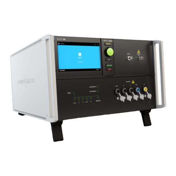
Page 18: Quick Start Guide Burst Nx8
AMETEK CTS Quick start guide - Single pulse generators Quick start guide burst NX8 6.1. Scope of delivery Using the following list, check that all the items ordered have been delivered: Item Name Remark Picture burst NX8 burst NX8 generator including... -
Page 19: Options
Pulse Verification Kit 1 Transducer plate Support Pulse Verification Fast Adapter 3 – MC to SHF PVF AD3 ESS 1 ESS 1 Interlock for burst NX8 #111607 Switches OFF High voltage and EUT power supply SCC AD Safety Circuit Adapter (Sys. Link) #111240... -
Page 20: Safety Instructions For Installation And Initial Installation
6.2.2. Installation The burst NX8 generator conforms to protection class 1. Local installation regulations must be respected to ensure the safe flow of leakage currents. WARNING Operation without a ground connection is forbidden! Two independent ground connections are necessary - one for the test system and one for the EUT. -
Page 21: Installation Of The Burst Nx8
AMETEK CTS Quick start guide - Single pulse generators 6.3. Installation of the burst NX8 6.3.1. installation site Place the test system so that there is enough free space around the cooling air inlets on both sides and behind the fan outlet on the rear panel. -
Page 22: Mains Switch And Fuse
Fuses for EUT with smaller nominal currents The AMETEK CTS pulse generators have no built-in fuse for the EUT power supply. It is in the scope of responsibility of the user to protect the EUT external for the rated current. -
Page 23: Eut Power On/Off With Supply Line To Line (400V)
AMETEK CTS Quick start guide - Single pulse generators Example of external circuit breaker Circuit breakers in the building are designed for 32 A. A circuit breaker box with 16 A protection is installed between the building supply and the test generator. -
Page 24: Front View (Model-Specific Distinctions)
AMETEK CTS Quick start guide - Single pulse generators 6.6. Front view (model-specific distinctions) HV pulse Burst output 50 Active indication Back Touch screen AC / DC test supply EUT test supply Coupling mode (50 output) Knob (Inc. / Dec /Enter) Ground reference (calibration) "... - Page 25 AMETEK CTS Quick start guide - Single pulse generators HV pulse Burst output 50 Active indication Back Touch screen AC / DC test supply EUT test supply Coupling mode (50 output) Knob (Inc. / Dec /Enter) Ground reference (calibration) "...
- Page 26 USB input (Memory Stick) Input plug for a memory stick for export / import test reports or test and link-files. The user can load from this port setup pictures, updates and other files to the burst NX8 generator. 1.00 26 / 88...
-
Page 27: Rear View (Model-Specific Distinctions)
1.000 V DC, 16 or 32 A depending on the model Ventilation A power-controlled ventilator is cooling the burst NX8 generator. During the most application the ventilator runs with variable speed depends on the cooling requirement. After long term duration tests the generator should keep on running for some minutes to cool down the system. - Page 28 USB interface “USB A” connector. Input plug for a memory stick for export / import test reports or test and link-files. The user can load from this port setup pictures, updates and other files to the burst NX8 generator USB interface B (for service purpose ONLY) USB interface “USB B”...
- Page 29 Sys Link output Sys link is the internal control bus to the connected burst NX8 devices. The sys link is a daisy chain wired bus for connect the devices in series. The bus includes a 26 pole high density connector. This port is terminated with the SWL AD (Safety Warning Lamp Adapter).
-
Page 30: Power On The Burst Nx8 Generator
Quick start guide - Single pulse generators 6.8. Power ON the burst NX8 generator Approx. 3-4 seconds after power on the generator will drive the ventilator at full speed during few seconds. Then the ventilator returns to a variable speed control concerning the temperature. -
Page 31: Quick Start Guide Vsurge Nx15/Nx20
AMETEK CTS Quick start guide - Single pulse generators Quick start guide vsurge NX15/NX20 7.1. Scope of delivery vsurge NX15 Using the following list, check that all the items ordered have been delivered: Item Name Remark Picture vsurge NX15 vsurge NX15 generator... -
Page 32: Options Vsurge Nx15
AMETEK CTS Quick start guide - Single pulse generators 7.3. Options vsurge NX15 Name Remark Picture SCC AD Safety Circuit Adapter (Sys. Link) Short circuit for Interlock ESS 1 ESS 1 Interlock for NX system Switches OFF high voltage and EUT power supply 7.4. -
Page 33: Options Vsurge Nx20
AMETEK CTS Quick start guide - Single pulse generators 7.6. Options vsurge NX20 Name Remark Picture PVV BOX 1 Pulse Verification Voltage Surge Box for vsurge NX20 verification including 11 different capacitor values: 22.5nF, 27.5nF, 32.5nF, 37.5nF, 45nF, 55nF, 67.5nF, 85nF, 105nF, 127.5nF, 155nF... -
Page 34: Mains Switch And Fuse
AMETEK CTS Quick start guide - Single pulse generators 7.7.1. Mains Switch and fuse The mains power voltage indicated on the instrument must correspond with the local supply voltage (mains voltage: 85–265 Vac, universal power unit, mains frequency: 50–60 Hz). -
Page 35: Safety Circuit, Warning Lamps
AMETEK CTS Quick start guide - Single pulse generators 7.8. Safety circuit, Warning lamps Safety circuit and warning lamps are located at each end of the Sys Link. Each End of the Sys.Link is terminated with an adapter. Safety circuit Plug position: SYS.LINK IN vsurge NX... -
Page 36: Safety Circuit
AMETEK CTS Quick start guide - Single pulse generators 7.8.1. Safety circuit The safety circuit locks the system and enables the generation of the high voltage impulses in the generators. Design Each device that has internal relevant high voltage unit, includes a safety circuit. -
Page 37: Front View Vsurge Nx15
AMETEK CTS Quick start guide - Single pulse generators 7.9. Front view vsurge NX15 Active indication " Test On" LED bar for charging voltage USB input (Memory stick) Start / Pause / Stop High/Low-output Touch screen CRO I (surge) Back CRO V (surge) CRO Trigger output ... - Page 38 AMETEK CTS Quick start guide - Single pulse generators Active indication " Test On" LED bar for charging voltage USB input (Memory stick) Start / Pause / Stop High/Low-output Touch screen CRO I (surge) Back CRO V (surge) CRO Trigger output 5V Knob (Inc.
-
Page 39: Rear View Vsurge Nx15
AMETEK CTS Quick start guide - Single pulse generators 7.10. Rear view vsurge NX15 Reference earth connection Sync input 11 Sys Link IN Ventilator Sys Link OUT 12 USB B interface Power On Switch Ethernet interface 13 USB A interface... - Page 40 AMETEK CTS Quick start guide - Single pulse generators Reference earth connection Sync input 11 Sys Link IN Ventilator Sys Link OUT 12 USB B interface Power On Switch Ethernet interface 13 USB A interface Mains input Opto Link Interface...
- Page 41 AMETEK CTS Quick start guide - Single pulse generators Reference earth connection Sync input 11 Sys Link IN Ventilator Sys Link OUT 12 USB B interface Power On Switch Ethernet interface 13 USB A interface Mains input Opto Link Interface...
-
Page 42: Power On The Vsurge Nx15 Generator
AMETEK CTS Quick start guide - Single pulse generators 7.11. Power ON the vsurge NX15 generator Approx. 3-4 seconds after power on the generator will drive the ventilator at full speed during few seconds. Then the ventilator returns to a variable speed control concerning the temperature. -
Page 43: Front View Vsurge Nx20
AMETEK CTS Quick start guide - Single pulse generators 7.13. Front view vsurge NX20 Active indication " Test On" LED bar for charging voltage USB input (Memory stick) Start / Pause / Stop EUT test supply Touch screen CRO I (surge) - Page 44 AMETEK CTS Quick start guide - Single pulse generators Active indication " Test On" LED bar for charging voltage USB input (Memory stick) Start / Pause / Stop EUT test supply Touch screen CRO I (surge) Polarity selection Back CRO U (surge) Range selection CRO Trigger output ...
- Page 45 AMETEK CTS Quick start guide - Single pulse generators Active indication " Test On" LED bar for charging voltage USB input (Memory stick) Start / Pause / Stop EUT test supply Touch screen CRO I (surge) Polarity selection Back CRO U (surge) Range selection CRO Trigger output ...
-
Page 46: Rear View Vsurge Nx20
AMETEK CTS Quick start guide - Single pulse generators 7.14. Rear view vsurge NX20 Reference earth connection Monitor V, Monitor I, (not used) 11 USB B interface Ventilator Fail, EUT 1, EUT2 12 Ethernet interface Mains input External Trigger IN... - Page 47 AMETEK CTS Quick start guide - Single pulse generators Reference earth connection Monitor V, Monitor I 11 USB B interface Ventilator Fail, EUT 1, EUT2 12 Ethernet interface Mains input External Trigger IN 13 Opto Link Interface Power On Switch...
- Page 48 AMETEK CTS Quick start guide - Single pulse generators Reference earth connection Monitor V, Monitor I 11 USB B interface Ventilator Fail, EUT 1, EUT2 12 Ethernet interface Mains input External Trigger IN 13 Opto Link Interface Power On Switch...
-
Page 49: Power On The Vsurge Nx20 Generator
AMETEK CTS Quick start guide - Single pulse generators 7.15. Power ON the vsurge NX20 generator Approx. 3-4 seconds after power on the generator will drive the ventilator at full speed during few seconds. Then the ventilator returns to a variable speed control concerning the temperature. -
Page 50: Quick Start Guide Vss 500N
AMETEK CTS Quick start guide - Single pulse generators Quick start guide VSS 500N Model overview Name 10’000 V VSS 500N10 < 100 ns / > 2 ms Ri = 1000 Ohm VSS 500N12 12000 V 18 J 1,2 µs / 50 µs Ri = 500 Ohm VSS 500N12.1... -
Page 51: Front View
AMETEK CTS Quick start guide - Single pulse generators 8.2. Front view Display Exit CRO Trigger Function key "F1..F7" Escape High Voltage Indication "TEST ON" CRO U for Peak Voltage (N12.x) High Voltage pulse output Knob (Inc/Dec) CRO I for Peak Current (N12.x) Safety circuit Cursor ""... -
Page 52: Rear View
AMETEK CTS Quick start guide - Single pulse generators 8.3. Rear View SYNC input Mains selector 115V / 230V 2 Reference earth connection Fuse of the high voltage power supply 3 Connection warning lamp Parallel interface GPIB / IEEE 488... -
Page 53: Operation Vss500N Generator
AMETEK CTS Quick start guide - Single pulse generators SYNC input Mains selector 115V / 230V Reference earth connection Fuse of the high voltage power supply Connection warning lamp Parallel interface GPIB / IEEE 488 Ventilator Opto Link interface (USB) -
Page 54: Menu Structure
AMETEK CTS Quick start guide - Single pulse generators EM TEST The serial number and the version number SWN are used for Surge traceability reasons. These numbers are listed in the test reports and calibration certificates. These numbers also are... -
Page 55: Technical Data Vss 500N12.X
AMETEK CTS Quick start guide - Single pulse generators Test level Selectable phase angle to superimpose the pulse to the mains (only with external CDN) Polarity of the generated pulse Not used in VSS generators rep (t1) Repetition rate of the generated pulses Trigger mode;... -
Page 56: Technical Data Vss 500N12.7
AMETEK CTS Quick start guide - Single pulse generators 8.8. Technical Data VSS 500N12.7 Impulse N1 ITU-T impulse generator as per IEC 60950 10 % Open circuit voltage 500 V - 12000 V Pulse circuit Figure N.1 as per IEC 60950 Annex N... -
Page 57: Quick Start Guide Css 500N2
AMETEK CTS Quick start guide - Single pulse generators Quick start guide CSS 500N2 9.1. Scope of delivery Using the following list, check that all the items ordered have been delivered: • Current surge generator type CSS 500 N2 •... -
Page 58: Front View
AMETEK CTS Quick start guide - Single pulse generators 9.3. Front view HV Output on top cover of CSS 500 N2 CRO trigger output 5V Display Exit "Test On" Escape 8/20s current pulse high Function keys "F1..F7” CRO U ( surge) 8/20s current pulse low... -
Page 59: Rear View
AMETEK CTS Quick start guide - Single pulse generators 9.4. Rear view Ventilation Parallel interface IEEE 488 EXT trigger input USB Serial interface Mains selector 115V / 230V Remote Control connector Power on switch Fail detection Ventilation After long term duration tests the generator should keep on running for some minutes to cool down the system. - Page 60 AMETEK CTS Quick start guide - Single pulse generators Fuse for high voltage power supply 12 Reference earth connection 10 Safety circuit 13 Sync input 11 Warning lamp Fuse F3 of the high voltage power supply The high voltage power supply unit is protected against overload by this fuse. In case that no pulses are generated anymore please check the fuse.
-
Page 61: Operation Css500N2 Generator
AMETEK CTS Quick start guide - Single pulse generators 9.5. Operation CSS500N2 generator The simulator CSS 500N2 is operated by an easy menu control system. Seven function keys are available to select parameters and functions. All functions are indicated on the display; max. 8 lines and 40 characters. -
Page 62: Quick Start
AMETEK CTS Quick start guide - Single pulse generators Page 2 CSURGE (1200A) F1 : Quick Start F2 : Usual Routine F3 : Change Voltage after n by V F4 : Change Phase angle after n by A F5 : Change Polarity after n pulses F1 Quick Start Easy and fast operation of the generator. -
Page 63: Technical Data
AMETEK CTS Quick start guide - Single pulse generators Any pressing of a function key will indicate the functions START, CHANGE or CONTINUE. F3 will continue the same test routine. Also the test time will continue running. If the user selects at first START or CHANGE the test will be stopped completely. -
Page 64: Quick Start Guide Ocs 500N6 / N6F
AMETEK CTS Quick start guide - Single pulse generators Quick start guide OCS 500N6 / N6F 10.1. Models Model name till 2008 coupling network AC voltage DC voltage OCS 500 N6 OCS 500 M6 1-phase 250 V / 16 A 250 V / 10 A OCS 500 N6.2... -
Page 65: Front View Ocs 500N6.X
AMETEK CTS Quick start guide - Single pulse generators 10.3. Front view OCS 500N6.x "Test On" LED coupling 1 ph. version Cursor keys "" and "→" Function keys "F1..F7 EUT test supply L, N, PE 1ph version Knob (Inc. / Dec.) Display LED coupling 3 ph. - Page 66 The direct HV and COM output of the generator is located at the front panel of the instrument. It is not allowed to connect these outputs to any other coupling/decoupling network than manufactured by AMETEK CTS, e.g. the types CNV or CNI.
-
Page 67: Rear View Ocs 500N6.X
AMETEK CTS Quick start guide - Single pulse generators 10.4. Rear view OCS 500N6.x EUT supply input neutral EUT power mains supply line Sync input Test supply input PE Reference earth connection Warning lamp Ventilation Safety Circuit EUT power mains supply input - Neutral The neutral N is conducted to the EUT via the coupling/decoupling network to the front panel output N. - Page 68 AMETEK CTS Quick start guide - Single pulse generators External trigger 13 Parallel interface IEEE 10 Power on switch and fuse 14 USB Serial interface 11 Mains selector 115V / 230V 15 Remote control connector 12 Fuse of the high voltage power supply...
-
Page 69: Front View Ocs 500N6F.x
AMETEK CTS Quick start guide - Single pulse generators 10.5. Front view OCS 500N6F.x "Test On" LED mains coupling 1/3 ph. Cursor keys "" and "→" Function keys "F1..F7 EUT test supply 1ph/3ph Knob (Inc. / Dec) Display Fast damped output for I/O lines Escape Direct output HV –... - Page 70 The direct HV and COM output of the generator is located at the front panel of the instrument. It is not allowed to connect these outputs to any other coupling/decoupling network than manufactured by AMETEK CTS, e.g. the types CNV or CNI.
-
Page 71: Rear View Ocs 500N6F.x
AMETEK CTS Quick start guide - Single pulse generators 10.6. Rear view OCS 500N6F.x EUT supply input neutral EUT power mains supply line Sync input Test supply input PE Reference earth connection Warning lamp Ventilation Safety Circuit EUT power mains supply input - Neutral The neutral N is conducted to the EUT via the coupling/decoupling network to the front panel output N. - Page 72 AMETEK CTS Quick start guide - Single pulse generators External trigger 10 Power on switch and fuse 11 Mains selector 115V / 230V 12 Fuse of the high voltage power supply 13 Parallel interface IEEE 14 Optical interface (USB) 15 Remote control connector...
-
Page 73: Description Of The Menus
These numbers are listed in the test reports Ringwave and calibration certificates. These numbers also are listed within OCS 500N6 the test reports generated by the Damped Oscillatory AMETEK CTS software ISM IEC. V 2.00 SWN: 001234 Start-up display example OCS 500N6 Page 0 Page 1... -
Page 74: Main Menu Ocs 500N6.X
AMETEK CTS Quick start guide - Single pulse generators 10.8. Main Menu OCS 500N6.x Page 1 MAIN MENU F1 : Damped Osc. 100 kHz IEC 61000-4-18 F2 : Damped Osc. 1MHz IEC 61000-4-18 F3 : Ringwave 100 kHz IEC 61000-4-12 F4 : Damped Osc. -
Page 75: Main Menu Ocs 500N6F.x
AMETEK CTS Quick start guide - Single pulse generators 10.9. Main Menu OCS 500N6F.x Page 1 MAIN MENU F1 Fast Damped Osc. IEC 61000-4-18 F2 Slow Damped Osc. IEC 61000-4-18 F3 Ringwave Gen. 100 kHz IEC 61000-4-12 F4 Damped Osc. -
Page 76: Main Menu Ocs 500N6F.x
AMETEK CTS Quick start guide - Single pulse generators 10.10. Main Menu OCS 500N6F.x Easy and very fast operation of all standard functions of the equipment. The latest simulator settings are stored automatically and will be recalled when Quick Start is next selected. -
Page 77: Technical Data - Slow Damped Oscillatory As Per Iec 61000-4-18
AMETEK CTS Quick start guide - Single pulse generators 10.11. Technical data - Slow damped oscillatory as per IEC 61000-4-18 Test Level 250 V – 2`500 V 10 % Output voltage 250 V – 3`000 V 10 % HV out on model N6.5;... -
Page 78: Quick Start Guide Nsg 3150
AMETEK CTS Quick start guide - Single pulse generators Quick start guide NSG 3150 11.1. Scope of delivery NSG 3150 Using the following list, check that all the items ordered have been delivered: 1. NSG 3150 generator 2. User manuals 3. -
Page 79: Front View Nsg 3150
AMETEK CTS Quick start guide - Single pulse generators 11.3. Front view NSG 3150 Reference ground connector The earth connection between the CDN and the generator is realized via the shield of the HV connectors. There is no need to connect the ground connector from the generator itself. -
Page 80: Rear View Nsg 3150
AMETEK CTS Quick start guide - Single pulse generators 11.4. Rear view NSG 3150 11.5. The standard user interface (SUI) The NSG 3150 Standard User Interface (SUI) consists of – A 7” color touch panel – A wheel for setting parameters –... -
Page 81: Installation
AMETEK CTS Quick start guide - Single pulse generators 11.6. Installation The NSG 3150 test system conforms to protection class 1. Local installation regulations must be respected to ensure the safe flow of leakage currents. WARNING - Operation without a ground connection is forbidden! Operate the equipment only in dry surroundings. -
Page 82: 11.10. Technical Data
AMETEK CTS Quick start guide - Single pulse generators ▪ Internal disruption of the electronics can result in the interference voltage or the EUT supply voltage being present on the EUT’s outer casing. ▪ Electrical breakdown or arcing from connections that are overstressed voltage wise during the test. -
Page 83: Coupling/Decoupling Network Cdn 3153-S63.1
AMETEK CTS Quick start guide - Single pulse generators 11.11. Coupling/decoupling network CDN 3153-S63.1 These CDN 3153-S63.1 is fully automatic controlled, featuring plug and play technology - just connect them to the NSG 3150 and they will auto detect and auto configure at system power up, available coupling possibilities will show up in respective test windows. -
Page 84: How To Use A Nextgen Device
AMETEK CTS Quick start guide - Single pulse generators How to use a NextGen device 12.1. 1. General safety instructions 1. Must be operated only by authorized and trained specialists 2. Do not operate without any ground connection 3. Hazardous high voltages are generated on the output terminal 12.2. -
Page 85: Control Elements
AMETEK CTS Quick start guide - Single pulse generators 12.4. 4. Control elements 1. Phenomenon 2. Advanced Menu 3. Brings you back to the Home Screen 4. Test and Control Buttons 5. Output and coupling options 12.5. 5. Home screen 1. -
Page 86: Pulse Settings
AMETEK CTS Quick start guide - Single pulse generators 12.7. 7. Pulse settings 1. Tap to select the parameter. Parameters written in white can be changed. Selected parameter is underlined. 2. Pulse Graphic. Press loupe-symbol to enlarge or swipe left and right to naviagte to other views. -
Page 87: Starting A Test
AMETEK CTS Quick start guide - Single pulse generators 12.10. 8. Starting a test 1. Press “TEST ON” to enable High voltage and power to the EUT 2. Press “START/PAUSE” to start a test. 3. Long press “START/PAUSE” for continuous test. -
Page 88: Maintenance, Adjustments, Replacement Of Parts
The user is not permitted to change or modify any EM TEST / TESEQ generator. Only original EM TEST / TESEQ parts and components shall be used for repair and service. AMETEK CTS is not responsible for accidents or injuries caused through the use of parts or components not sold by AMETEK CTS.
Need help?
Do you have a question about the burst NX8 and is the answer not in the manual?
Questions and answers