Table of Contents
Advertisement
The benchmark for emc
M a n u a l
F o r
O p e r a t i o n
AMP 200N
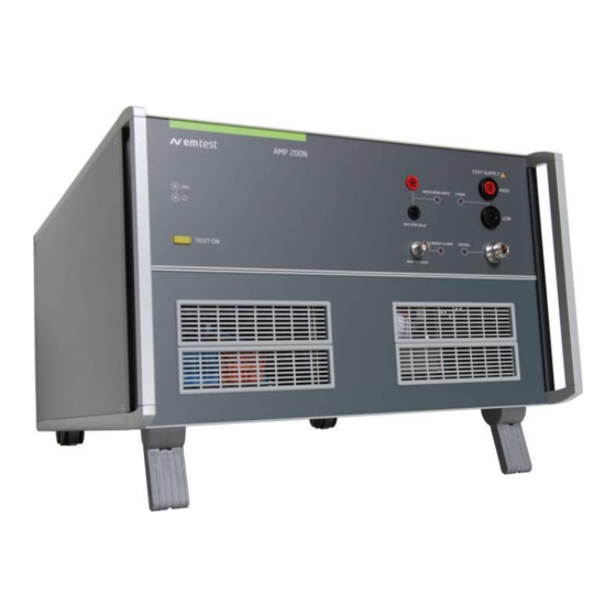
AMP 200N1.1
AMP 200N2
Low frequency signal source for supply
simulation and magnetic fields
The AMP 200N series has been designed as a low-frequency
signal source to generate sinusoidal signals used to simulate
ripple noise and ground shift noise as required by a variety of
standards in the automotive, aircraft and military industry.
The AMP 200N devices is controlled by the EM TEST Autowave
to also allow the generation of non-sinusoidal and customized
signals. Additionally, the AMP 200N series can be used to
generate magnetic fields by means of a radiation loop or small
Helmholtz coils.
Version: 4.0.3 / 23.11.2020
Replaces: 4.0.2 / 18.10.2019
Filename: UserManual-AMP200N-E-
V4.0.3_reformatted.doc
Printdate: 23.11.20
•
Ford FMC 1278
•
Ford EMC-CS-2009
•
ISO 11452-8
•
ISO 7637-4 (Draft)
•
LV 123
•
SAE J1113-2
•
Daimler Chrysler DC xx
•
Fiat 9.90110
•
GMW3097
•
PSA/Renault EQ/IR 02
•
VW TL 82566
•
Mercedes MBN 10284-2
•
Nissan 28401 NDS 02
•
GLoyd GL VI-7-2
Advertisement
Table of Contents

Related Manuals for Ametek AMP 200N


Summary of Contents for Ametek AMP 200N
- Page 1 LV 123 standards in the automotive, aircraft and military industry. • SAE J1113-2 The AMP 200N devices is controlled by the EM TEST Autowave • Daimler Chrysler DC xx • to also allow the generation of non-sinusoidal and customized Fiat 9.90110...
- Page 2 Sternenhofstrasse 15 4153 Reinach BL1 Switzerland Phone: +41 61 717 91 91 Fax: +41 61 717 91 99 URL: http://www.emtest.com Copyright © 2018 AMETEK CTS GmbH All right reserved. Specifications subject to change Manual for Operation V 4.0.3 2 / 60...
-
Page 3: Table Of Contents
Calibration and Verification ....................... 28 11.2.1 Factory calibration ..........................28 11.2.2 Guideline to determine the calibration period of AMETEK CTS instrumentation ......28 11.2.3 Calibration of Accessories made by passive components only ............28 11.2.4 Periodically In-house verification ...................... 28 Application ........................ - Page 4 Using Capacitive loads ........................29 12.2 Power setup AMP 200Nx ......................... 30 12.3 Test setup for AMP 200N Series application ..................30 12.4 Setup for Ford EMC CS 2009-1 ....................... 33 12.4.1 Setup for Magnetic Field Immunity: RI 140 ..................34 12.4.2 General Information about Magnetic Immunity ................
-
Page 5: Safety
AMETEK CTS AMP 200N series Safety Safety Aspects Observe all precautions to assure your personal safety. The generators comply with Installation Category II (excess voltage section). Pay special attention to safety and operation details! Safety and warning label on the device Please take note of the following explanations of the symbols used in order to achieve the optimum benefit from this manual and to ensure safety during operation of the equipment. -
Page 6: Responsibility Of The Operator
AMETEK CTS AMP 200N series To avoid personal injury, do not operate the generators without panels and covers. Do Not Operate in an Explosive Environment Electric Overload Never apply power to a connector which is not specified for that particular voltage/current. -
Page 7: Qualification Of Personnel
AMETEK CTS AMP 200N series Neither AMETEK CTS GmbH, nor any of the subsidiary sales organizations can accept any responsibility for personnel, material or inconsequential injury, loss or damage that results from improper use of the equipment and accessories. WARNING... -
Page 8: Standards Covered By Amp 200N Series
Ford, CI 210 and CI 250 as well as RI 150. The AMP 200N is controlled by the EM TEST Autowave to also allow the generation of non-sinusoidal and customized signals. -
Page 9: Delivery Groups And Put In Service
Identical accessory parts are delivered only once if several devices are ordered. The delivered packing list is in each case valid for the delivery. Basic equipment AMP 200N Series • Pulse generator type AMP 200N, AMP 200N1.1 and AMP 200N2 • Power Mains cable Country specific plug • Control cable (Framebus) SubD 15 pin male / female for AMP200N to (AutoWave or NetWave) •... -
Page 10: Accessories
AMETEK CTS AMP 200N series Accessories 3.2.1 Frame Bus Termination • Frame Bus terminating for matching the end of the framebus. The framebus, an internal bus system, is used for control EM Test devices and work as daisy chain between the equipment. Longer bus systems must be terminated with a Frame bus termination. -
Page 11: Operating Functions Amp200N
AMETEK CTS AMP 200N series Operating Functions AMP200N Front view Figure 1 1. TEST ON 6. 2 wire output indication 2. LED Power 7. 2 wire output 3. LED Fail 8. Coaxial output 4. Measuring input 9. Coaxial output indication 5. -
Page 12: Rear View
Control output to system dc source (normally VDS200N). The control signal is generated in the AutoWave or AMP 200 internal and pass through the AMP200N to the “analog IN” of the VDS200N. Offset OUT Output control signal from the AMP 200N internal DC source (-10V to +10V). Manual for Operation V 4.0.3... - Page 13 AMETEK CTS AMP 200N series Reference earth connection The generator has to be connected to the reference earth plane of the test set up. Manual for Operation V 4.0.3 13 / 60...
-
Page 14: Operating Functions Amp200N1.1 And Amp 200N2
Power On Indication of the present mains power. The illuminated LED shows the power on status. LED Fail Indication of different Fail status of the AMP 200N, such as: Overtemperature, Overload, internal Fail, Safety Circuit Fail Reset: Press OK in the software Fail window, wait 2 seconds and press AMP200N Test ON button. -
Page 15: Rear View
AMETEK CTS AMP 200N series Figure 4 1. TEST ON 6. 2 wire output indication 2. LED Power 7. 2 wire output 3. LED Fail 8. Coaxial output 4. Measuring input 9. Coaxial output indication 5. Measuring input enabled 10. Current clamp input enabled 11. - Page 16 CH 2 IN BNC input -10V to +10V to internal amplifier. Offset OUT Output control signal from the AMP 200N internal DC source (-10V to +10V). Ventilation The cooling output needs at least 20cm space for a free airflow. Manual for Operation V 4.0.3...
- Page 17 AMETEK CTS AMP 200N series Figure 6 Framebus Ventilation Reference earth connection Mains Fuse Signal OUT Safety Circuit CH 1 IN Mains input CH 2 IN Power on switch Offset OUT Mains selector 115V / 230V Mains Fuse Mains AMP 200N2 AMP 200N1.1...
- Page 18 AMETEK CTS AMP 200N series Figure 7 Framebus Ventilation Reference earth connection Mains Fuse Signal OUT Safety Circuit CH 1 IN Mains input CH 2 IN Power on switch Offset OUT Mains selector 115V / 230V See AMP 200N1.1, except SIGNAL OUT. The AMP 200N2: The SIGNAL OUT output is only active when the AMP is turned on.
-
Page 19: Operation
AMP 200N series Operation The AMP 200N needs an AutoWave generator or a Netwave for operate. The AutoWave/Netwave generator controls the AMP 200N via the framebus. The user needs the autowave.control or Netwave.controlsoftware for operate the system with the AMP200N. -
Page 20: Output Range Setting For Dc Application
AMP 200Nx as DC source It is generally not recommended to use the AMP 200N series as a DC source, but if necessary, it is recommended to check in advance the equipment maximum current consumption during the test. Then select the suitable output range for equipment operation. - Page 21 AMP 200N series Overcurrent alarm appears when DUT current exeeds Imax ! AMP 200N is only suitable as DC source when DUT current consumption is < Imax under all conditions (Inrush, overshoot, peak, transient current). Even µs overcurrent will trip the AMP...
-
Page 22: Test Equipment Amp 200N
DC supply +5V , ± 15V Transformer Cooling Restriction for cooling behavior. Rack: No restriction where to install the AMP 200N. The rack internal cooling must be warranted. Other: For cooling the AMP200N a minimum free space at the rear of 20cm is requested. -
Page 23: Framebus Interface Module
AMETEK CTS AMP 200N series Framebus Interface Module The framebus interface module with the following blocks: Controller: Communication with the AutoWave generator DC Source: DC source for the offset Out signal Signalgenerator: Generator for the sine signal up to 500kHz. The signal can be shifted by a dc offset. -
Page 24: Technical Data Amp200N
Frequency range Output voltage ±10 V Dc offset ±10 V, programmable, to control external DC amplifier Measurements (optional) Measuring Unit AMP 200N Frequency-selective instrument for voltage, current and magnetic field 10 Hz – 250 kHz Frequency range Accuracy Better than 5%... -
Page 25: Technical Data Amp200N1.1
Frequency range Output voltage ±10 V Dc offset ±10 V, programmable, to control external DC amplifier Measurements (optional) Measuring Unit AMP 200N Frequency-selective instrument for voltage, current and magnetic field 10 Hz – 250 kHz Frequency range Accuracy Better than 5%... -
Page 26: Technical Data Amp200N2
Dc offset ±10 V, programmable, to control external DC amplifier 10.3 Measurements (optional) Measuring Unit AMP 200N Frequency-selective instrument for voltage, current and magnetic field 10 Hz – 250 kHz Frequency range (External oscilloscope must be used to measure beyond 250 kHz) - Page 27 AMETEK CTS AMP 200N series Temperature 10°C - 40°C Humidity 20 to 85% relative humidity (RH non condensing) Manual for Operation V 4.0.3 27 / 60...
-
Page 28: Maintenance
AMETEK CTS equipment. AMETEK CTS doesn’t know each customer’s Quality Assurance Policy nor do we know how often the equipment is used and what kind of tests is performed during the life cycle of test equipment. Only the customer knows all the details and therefore the customer needs to specify the calibration interval for his test equipment. -
Page 29: Application
AMETEK CTS AMP 200N series 12 Application The AMP 200N is a multi using instrument with a large number of applications. In general the AMP 200N can be used for the following two groups of application: Immunity tests Different devices like Radiating loop or Coupling Network (CN200) are connected to the Test supply output. -
Page 30: Power Setup Amp 200Nx
Immunity Test Check output voltage before connect any devices DC source 13.5V Power setup when using the AMP 200N for immunity tests and using as dc source. 12.3 Test setup for AMP 200N Series application The following setup shows different setup with EM Test devices for testing with AMP200N. The list is not complete. - Page 31 AMETEK CTS AMP 200N series Setup 5: example with: Rack LD 200N AMP 200N AutoWave UCS 200N VDS 200Nx Figure 11 Setup 5 Manual for Operation V 4.0.3 31 / 60...
- Page 32 AMETEK CTS AMP 200N series Setup 6: example with: Rack LD 200N AMP 200N AutoWave PFS500N RDS200 UCS 200N VDS 200Nx Figure 12 Setup 6 Manual for Operation V 4.0.3 32 / 60...
-
Page 33: Setup For Ford Emc Cs 2009-1
AMETEK CTS AMP 200N series 12.4 Setup for Ford EMC CS 2009-1 These requirements are related to component immunity from wire-to wire coupling of unintended transient disturbances. The originate of these disturbances are from switching of inductive loads including solenoids and motors. -
Page 34: Setup For Magnetic Field Immunity: Ri 140
AMETEK CTS AMP 200N series Standard setup as per Ford Rack 1 DC sources Rack 2 Pulses For complete transient testing as per Ford standard, the following RDS 200N control: AutoWave CH4 or PFS200 LD 200N setup shows the wiring between... - Page 35 AMETEK CTS AMP 200N series Figure 15 Setup for RI 140 If MN HField box is used the bridge must be shorted RI 140 Test Parameter requirements Figure 16 Graph for RI 140 Range Frequency [kHz] Level [dBpT rms] Frequency step [kHz] 0.05 –...
- Page 36 AMETEK CTS AMP 200N series Test characteristics Default settings as per Standard Method: Coupling Method : Radiated Test Regulation Method: Magnetic field (Calculation) Diagram Unit X-Axis : kHz ; Log Y-Axis: dBpT Tolerances Tolerances : +10% -0% Additional Settings: Additional Level Offset...
-
Page 37: General Information About Magnetic Immunity
Transform the current into a rms ac voltage Current Probe Current Shunt 12.4.2 General Information about Magnetic Immunity Below is an overview of the field strength limits using various AMP 200N models. Manual for Operation V 4.0.3 37 / 60... -
Page 38: Setup For Coupled Immunity: Ri 150
AMETEK CTS AMP 200N series Generally speaking the larger the coil, the more current and/or windings you need to get the desired field strength inside the coil. The more windings, the higher the resistance and therefore the more voltage you need to get a certain current into the coil to achieve the desired field strength. - Page 39 AMETEK CTS AMP 200N series Figure 17 Setup for RI 150 RI 150 Test Parameter requirements Figure 18 Graph for RI 150 Range Frequency [kHz] Level [I p-p] Frequency step [kHz] 1 – 10 Range 1 6 – 5.4 log (f/10)
- Page 40 AMETEK CTS AMP 200N series Test characteristics for RI 150 Default settings as per Standard Method: Coupling Method : Conducted Test Regulation Method: Current Level ( Closed Loop) Diagram Unit X-Axis : kHz ; log Y-Axis: A pk-pk ; linear...
-
Page 41: Immunity From Continuous Power Line Disturbances: Ci 210
AMETEK CTS AMP 200N series 12.4.4 Immunity from Continuous Power Line Disturbances: CI 210 The device shall be immune from continuous disturbances that occur on the vehicle’s low voltage (i.e. 13.5 VDC) electrical distribution system. Default test setup Figure 19 Setup for CI 210 closed loop with scope... - Page 42 AMETEK CTS AMP 200N series Test characteristics for CI 210 Method: Coupling Method : Conducted Test Regulation Method: Voltage Level ( Closed Loop) Disturbance Current limit : yes/no setted value Diagram Unit X-Axis : kHz ; Log Example Closed Loop Y-Axis: Vpp ;...
-
Page 43: Immunity To Ground Voltage Offset: Ci 250
AMETEK CTS AMP 200N series 12.4.5 Immunity to Ground Voltage Offset: CI 250 Components shall be immune from AC ground offset voltages. Requirements include both continuous and transient disturbances. Default test setup Continuous Disturbances Figure 21 Setup for CI 250... - Page 44 AMETEK CTS AMP 200N series Test characteristics for CI 250 continuous interference Method: Coupling Method : Conducted Test Regulation Method: Voltage Level (Closed Loop) Disturbance Current limit : yes/no setted value Diagram Unit X-Axis : kHz ; Log Y-Axis: Vpp ; linear...
- Page 45 AMETEK CTS AMP 200N series Default test setup Transient Disturbances Transient disturbances consist of a damped sinusoidal pulse with a resonant frequency of 100 kHz illustrated in Figure 8.16. The pulse is applied using the delay sequence illustrated in Figure 8.17.
- Page 46 AMETEK CTS AMP 200N series Test characteristics for CI 250 Transient interference Signal Adjust the coupling factor The used Solar transformer 6220-1A has a 2:1 turns ratio transformation at 1kHz. This ratio will change with higher frequencies. At 100kHz the effective ratio is more like 16:1. EM Test thinks the inter-winding capacitance results in a higher than anticipated drive voltage to produce the +/-5V signal at the secondary.
-
Page 47: Immunity To Sae J1113-2
AMETEK CTS AMP 200N series User Software settings The user has to complete the test settings with his individual used coupling and measuring devices. New coupling devices can be installed in the menu Setup/Coupling Device by the user. A: Voltage Measuring Instrument: The software needs no measuring instrument for control. - Page 48 AMETEK CTS AMP 200N series Figure 26 Setup for SAE J1113-2 SAE J1113-2 Test Parameter requirements Figure 27 Graph for SAE J1113-2 Range Frequency [kHz] Us [Vp-p] Frequency step 0.015 – 250 Range 1 0.15 Manual for Operation V 4.0.3...
- Page 49 AMETEK CTS AMP 200N series Test characteristics for SAE J1113-2 continuous interference Method: Coupling Method : Conducted Test Regulation Method: Voltage Level (Closed Loop) Disturbance Current limit : 1 A Diagram Unit X-Axis : kHz ; Log Y-Axis: Vpp ; linear...
-
Page 50: Immunity To Gloyd Gl Vi-7-2 - 20 (Dc)
AMETEK CTS AMP 200N series Immunity to GLoyd GL VI-7-2 – 20 (DC) 12.6 11.6.1. DC power supply For loading this testfile the user has to open the file “GL VI-7-2 – 20 (DC).wim”. Press in the main Window “Immunity play”... - Page 51 AMETEK CTS AMP 200N series Test characteristics for GL VI-7-2-20 (DC) continuous interference Vector 1: Name : Vector 1 Start: Level: 3V Frequency 0.05Hz Stop : Level: 3V Frequency 10.kHz Step Type: Percentage Value: Method: Coupling Method : Conducted Test Regulation Method:...
-
Page 52: Ripple Immunity With Voltage And Current Measurement
Figure 30 Setup for ripple immunity with swapped voltage and current measurement channels The above figure shows the setup for a closed-loop ripple immunity testing. The AMP 200N measurement channels are used to measure the ripple current and voltage at the EUT terminals. - Page 53 Software setup Setup with voltage and current inputs used in the normal way. Voltage Monitor In this case the internal AMP 200N voltage measuring input is used (4mm lab connector input). PVS 7 as differential voltage probe with 1000:1 ratio...
- Page 54 This setup can be used to increase the sensitivity on the voltage measurement. The current input offers higher sensitivity (100 mV / A or 100 mV / V) compared to the voltage input. Voltage Monitor In this case the internal AMP 200N voltage measuring input is used (4mm lab connector input). Current Monitor In this case the internal AMP 200N current measuring input is used (BNC connector input).
-
Page 55: Waveform Verification
AMETEK CTS AMP 200N series 13 Waveform Verification The Waveform verification is made at the AMP200N output plugs. 13.1 RI 140 H-Field verification Verification test setup Figure 31 Setup for RI 140 short circuit disconnected at the MN HField box... - Page 56 AMETEK CTS AMP 200N series Test characteristics Default settings as per Standard Method: Coupling Method : Radiated Test Regulation Method: Verify H-Field Diagram Unit X-Axis : kHz ; Log Y-Axis: dBpT ; Log Tolerances Tolerances : +2.7% -0% Additional Settings:...
- Page 57 AMETEK CTS AMP 200N series Magnetic Field Monitor: Measuring Instrument (AC current) 1. Instrument AMP Internal 2. Instrument value Voltage Measuring Equipment 3. Equipment Type H-Field sensor 4. Equipment Sensor name B: Measuring Instrument (Magnetic Field [dBpT]) : The current measuring is realized with a current probe connected to a measurement receiver. This instrument will measure the transferred ac voltage.
-
Page 58: Ci 250 Pulse Verification
AMETEK CTS AMP 200N series 13.2 CI 250 Pulse verification CI 250 Test Parameter requirements Peak measurement Upeak 5.00 3.65 2.67 1.95 1.42 1.04 0.76 0.55 0.41 0.30 Tolerances: Time interval ± 10% Voltage +10% -0% Climatic Test conditions Temperature 23±... -
Page 59: Appendix
AMETEK CTS AMP 200N series 14 Appendix 14.1 Declaration of CE-Conformity Manufacturer: AMETEK CTS GmbH Address: Sternenhofstr. 15 CH 4153 Reinach BL1 Switzerland declares, that under is sole responsibility, the product’s listed below, including all their options, are conformity with the applicable CE directives listed below using the relevant section of the following EC standards and other normative documents. -
Page 60: Radiating Loop H-Field Versus Antenna Current
EM TEST AMP 200 14.2 Radiating Loop H-Field versus antenna current Green range : Normal operating Red Range : Additional lower range with matching network Manual for Operation V 4.0.3 60 / 60...
Need help?
Do you have a question about the AMP 200N and is the answer not in the manual?
Questions and answers