Table of Contents
Advertisement
The benchmark for emc
M a n u a l
F o r
O p e r a t i o n
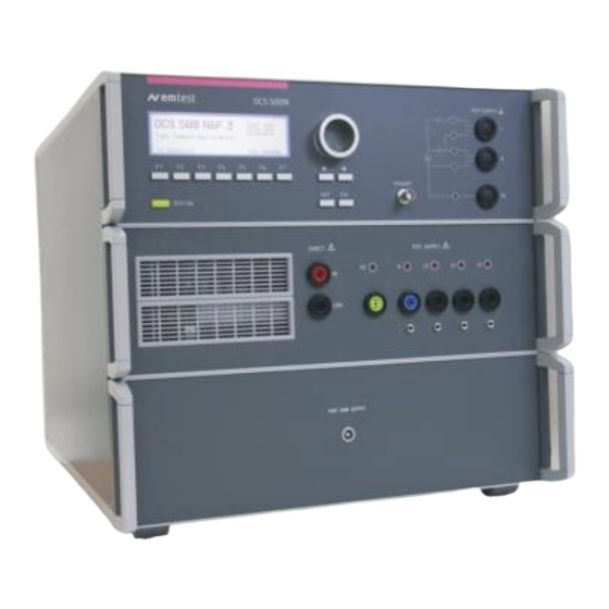
OCS 500N6 series
OCS 500N6F series
The Damped Oscillatory and
Ring Wave generator in one box
OCS 500N6x series - designed as a modular system - is the
most intelligent solution offering exactly what you need for full-
compliant immunity tests against damped oscillatory and ring
wave phenomena. The distinct operation features, convenient
DUT connection facilities, a clearly arranged menu structure and
display philosophy as well as the pre-programmed standard test
routines make testing easy, reliable and safe. Extendable by a
variety of test accessories the OCS 500N6 is universal
equipment for abroad range of recommendations even for three-
phase applications up to 100A.
Version: 5. 24 / 17.03.2021
Replaces: 5. 23 / 13.12.2018
File name
UserManual-OCS500N6-E-V5.24.doc
Print Date 17.03.21
ANSI /IEEE C62.41
ANSI /IEEE C37.90
EN/IEC 61000-4-10
EN/IEC 61000-4-12
EN/IEC 61000-4-18
IEC 60255-1
Advertisement
Table of Contents

Related Manuals for Ametek OCS 500N6 Series


Summary of Contents for Ametek OCS 500N6 Series
- Page 1 M a n u a l F o r O p e r a t i o n OCS 500N6 series OCS 500N6F series The Damped Oscillatory and Ring Wave generator in one box OCS 500N6x series - designed as a modular system - is the ANSI /IEEE C62.41...
- Page 2 4153 Reinach BL1 Switzerland Phone: +41 61 204 41 11 Fax: +41 61 204 41 00 URL : http://www.ametek-cts.com Copyright © 2021 AMETEK CTS GmbH All right reserved. Specifications subject to change Manual for Operation V 5.24 2 / 80...
-
Page 3: Table Of Contents
AMETEK CTS OCS 500 N6 series Contents General ..........................5 1.1. Purpose .............................. 5 1.2. Safety label on the device ........................5 1.3. Standards covered by OCS 500N6 / N6F generators ................ 6 1.4. Models and options ..........................6 1.5. - Page 4 Calibration and Verification ....................... 63 10.2.1. Factory calibration ..........................63 10.2.2. Guideline to determine the calibration period of AMETEK CTS instrumentation ......63 10.2.3. Calibration of Accessories made by passive components only ............63 10.2.4. Periodically In-house verification ...................... 63 10.3.
-
Page 5: General
AMETEK CTS OCS 500 N6 series General 1.1. Purpose The compact OCS 500Nx generator is a multifunction compact generator that simulates conducted electromagnetic interference effects for immunity testing to international, national, and manufacturers’ standards. The system is designed for full compliance conducted electromagnetic compatibility (EMC) test requirements. -
Page 6: Standards Covered By Ocs 500N6 / N6F Generators
AMETEK CTS OCS 500 N6 series 1.3. Standards covered by OCS 500N6 / N6F generators Fully equipped OCS 500N6 / N6F generators cover the following standards - IEC 61000-4-10 Oscillatory Magnetic Field test Ring wave immunity test - IEC 61000-4-12 - ANSI-IEEE C62.41.2... -
Page 7: Special Models
AMETEK CTS OCS 500 N6 series 1.5. Special Models Modell Remarks AC voltage DC voltage OCS500N6.1 Damped Oscillatory generator as per IEC 61000-4-18 incl 250V/16A 250V / 10A Damped Oscillatory waveform 100kHz and 1MHz No Ringwave module OCS500N6.9 With built-in Ringwave module only, 1 phase CDN... -
Page 8: Operating Functions
AMETEK CTS OCS 500 N6 series Operating Functions 2.1. OCS 500N6.x models 2.1.1. Front view OCS 500N6.x "Test On" LED coupling 1 ph. version Cursor keys "" and "→" Function keys "F1..F7 10 EUT test supply L, N, PE 1ph version Knob (Inc. - Page 9 The direct HV and COM output of the generator is located at the front panel of the instrument. It is not allowed to connect these outputs to any other coupling/decoupling network than manufactured by AMETEK CTS, e.g. the types CNV or CNI. Before to connect any external networks to this output the operator must contact the manufacturer.
-
Page 10: Rear View Ocs 500N6.X
AMETEK CTS OCS 500 N6 series 2.1.2. Rear view OCS 500N6.x 1 EUT supply input neutral 2 EUT power mains supply line 3 Sync input 4 Test supply input PE 5 Reference earth connection 6 Warning lamp 7 Ventilation 8 Safety Circuit EUT power mains supply input - Neutral The neutral N is conducted to the EUT via the coupling/decoupling network to the front panel output N. - Page 11 AMETEK CTS OCS 500 N6 series 9 External trigger 13 Parallel interface IEEE 10 Power on switch and fuse 14 USB Serial interface 11 Mains selector 115V / 230V 15 Remote control connector 12 Fuse of the high voltage power supply...
-
Page 12: Ocs 500N6F Models
AMETEK CTS OCS 500 N6 series 2.2. OCS 500N6F models 2.2.1. Front view OCS 500N6F.x "Test On" LED mains coupling 1/3 ph. Cursor keys "" and "→" Function keys "F1..F7 10 EUT test supply 1ph/3ph Knob (Inc. / Dec) Display... - Page 13 The direct HV and COM output of the generator is located at the front panel of the instrument. It is not allowed to connect these outputs to any other coupling/decoupling network than manufactured by AMETEK CTS, e.g. the types CNV or CNI. Before to connect any external networks to this output the operator must contact the manufacturer.
-
Page 14: Rear View Ocs 500N6F.x
AMETEK CTS OCS 500 N6 series 2.2.2. Rear view OCS 500N6F.x 1 EUT supply input neutral 2 EUT power mains supply line 3 Sync input 4 Test supply input PE 5 Reference earth connection 6 Warning lamp 7 Ventilation 8 Safety Circuit EUT power mains supply input - Neutral The neutral N is conducted to the EUT via the coupling/decoupling network to the front panel output N. - Page 15 AMETEK CTS OCS 500 N6 series 9 External trigger 10 Power on switch and fuse 11 Mains selector 115V / 230V 12 Fuse of the high voltage power supply 13 Parallel interface IEEE 14 Optical interface (USB) 15 Remote control connector...
-
Page 16: Operation
These numbers are listed in the Ringwave test reports and calibration certificates. These numbers OCS 500N6 also are listed within the test reports generated by the AMETEK CTS software ISM IEC. Damped Oscillatory SWN: 001234 V 2.00 Start-up display example OCS 500N6 Manual for Operation V 5.24... -
Page 17: Menu Structure
AMETEK CTS OCS 500 N6 series 3.2. Menu structure Page 0...4 Page 0 Page 1 Page 2 Page 3 Page 4..x MAIN MENU Damp. Osc.100kHz Quick Start Start IEC 61000-4-18 F1 Damped Osc. 100kHz IEC 61000-4-18 F1 Quick Start F1 Start Start the test routine F2 Damped Osc. -
Page 18: Main Menu Ocs 500N6.X
AMETEK CTS OCS 500 N6 series 3.3. Main Menu OCS 500N6.x Page 1 MAIN MENU F1 : Damped Osc. 100 kHz IEC 61000-4-18 F2 : Damped Osc. 1MHz IEC 61000-4-18 F3 : Ringwave 100 kHz IEC 61000-4-12 F4 : Damped Osc. -
Page 19: Main Menu Ocs 500N6F.x
AMETEK CTS OCS 500 N6 series 3.4. Main Menu OCS 500N6F.x Page 1 MAIN MENU F1 Fast Damped Osc. IEC 61000-4-18 F2 Slow Damped Osc. IEC 61000-4-18 F3 Ringwave Gen. 100 kHz IEC 61000-4-12 F4 Damped Osc. 1MHz ext. IEC 60255-26... -
Page 20: Phase Synchronization In 3-Phase System
AMETEK CTS OCS 500 N6 series 3.5. Phase synchronization in 3-phase system The built in hardware phase synchronization is between the sync input and PE. The user must connect the synchronize line L1 with the sync plug. The synchronization is based on a 3-phase system where neutral is connected to PE in the supply system. -
Page 21: Service
F7 : Status F1 Addresses The addresses of the AMETEK CTS GmbH in Switzerland and Germany are shown. The addresses of all AMETEK CTS sales agencies are listed on the web site of EM TEST under : www.emtest.com F2 Set-up The software will clearly explain the set-up procedure. - Page 22 AMETEK CTS OCS 500 N6 series Page 4 General Change standard level SETUP Change standard levels V : 250 V – 2500 V Level1 Level 2 Level 3 Coupling 500V 1000V 2500 DIFF F1, F2, F3 For each coupling (Differential mode and Common mode) a separate level can be settled.
-
Page 23: Setup
AMETEK CTS OCS 500 N6 series 3.7. Setup Page 3 SETUP F1 : Change language F2 : LCD - Backlighting F3 : Interfaces F4 : Beeper F5 : Power – on counter F1 Change language The user can chose between two languages, German and English. The user can chose between two languages, German and English. -
Page 24: Test Equipment Ocs 500 Nx
AMETEK CTS OCS 500 N6 series Test Equipment OCS 500 Nx 4.1. Assembling OCS 500N6 Rearpanel Frontpanel Control unit Power supply board 4 Power supply transformer Interface board 5 Filter board / connecting board Controller board 6 Keyboard / LCD- display... -
Page 25: Assembling Ocs 500N6Fx
AMETEK CTS OCS 500 N6 series 4.2. Assembling OCS 500N6Fx Control unit Power supply board 6 Power supply transformer Interface board 7 Filter board / connecting board Controller board 6 Keyboard / LCD- display High voltage unit General power supply input, filter... -
Page 26: Technical Data
AMETEK CTS OCS 500 N6 series Technical data 5.1. Slow damped oscillatory as per IEC 61000-4-18 Test Level 250 V – 2`500 V 10 % Output voltage 250 V – 3`000 V 10 % HV out on model N6.5; N6.6; N6.7; N6.8 Wave form (open circuit): 75 ns ... - Page 27 AMETEK CTS OCS 500 N6 series Test routines Quick Start Immediate start, all parameters adjustable during a running test Standard test as per IEC 61000-4-18 level 1 up to level 3 IEC 61000-4-18 Manual operated standard test routine User test routines...
-
Page 28: Fast Damped Oscillatory As Per Iec 61000-4-18
AMETEK CTS OCS 500 N6 series 5.2. Fast damped oscillatory as per IEC 61000-4-18 Test Level 450V – 4`400 V 10 % Output voltage Wave form (open circuit): 5 ns 30 % Rise time 3 MHz, 10 MHz, and 30 MHz 10 %... -
Page 29: Ringwave Immunity Requirements As Per Ansi C 62.41 (Iec 61000-4-12)
AMETEK CTS OCS 500 N6 series 5.3. RINGWAVE Immunity requirements as per ANSI C 62.41 (IEC 61000-4-12) Test level 250 V – 6‘000 V ± 10 % Open circuit voltage Wave shape open circuit 0.5 μs ± 30 % Rise time first peak T1 Oscillation frequency 1/T 100 kHz ±... -
Page 30: General Specifications Ocs 500N6.X
AMETEK CTS OCS 500 N6 series 5.4. General Specifications OCS 500N6.x DUT Supply OCS 500 N6.5 built in 1- phase coupling network 250 V 16 A ac 250 V/16 A dc OCS 500 N6.6 N6.2 built in 1- phase coupling network... -
Page 31: General Specifications Ocs 500N6F.x
AMETEK CTS OCS 500 N6 series 5.5. General Specifications OCS 500N6F.x DUT Supply OCS 500 N6F built in 1- phase coupling network 250 V 16 A ac 250 V/16 A dc OCS 500 N6F.1 built in 1- phase coupling network... -
Page 32: Damped Oscillatory 100 Khz Or 1 Mhz As Per Iec 61000-4-18
AMETEK CTS OCS 500 N6 series Damped Oscillatory 100 kHz or 1 MHz as per IEC 61000-4-18 This phenomenon is representative of switching of isolators in HV / MV open-air stations, and is particularly related to the switching of HV bus-bars, as well as of background disturbances in industrial plants. -
Page 33: Quick Start
AMETEK CTS OCS 500 N6 series 6.1.1. Quick start Easy and very fast operation of all standard functions of the equipment. The latest simulator settings are stored automatically and will be recalled when Quick Start is next selected. Page 3 Damped Osc. -
Page 34: Standard Test Routines
AMETEK CTS OCS 500 N6 series 6.1.2. Standard test routines The user can select preprogrammed standard test routines. Page 3 Damped Osc. 1MHz IEC 61000-4-18 F1 : Common Mode L-PE, N-PE L+N - PE F2 : Differential Mode Page 4 Damped Osc. - Page 35 AMETEK CTS OCS 500 N6 series 6.1.2.2. Manual testing The manual test menu is only in the single phase equipment available. Manual standard test routine Damped Osc. 1MHz IEC 61000-4-18 <- -> + 2000V Level 3 L PE 400/s Testtime 0:00:45 h...
-
Page 36: User Test Routines
AMETEK CTS OCS 500 N6 series 6.1.3. User Test Routines The user can program, save and recall his own specific test routines. The next pages show the selection of the functions. Damped Oscillatory User test routines F1 : Synchronized F2 : Random release... -
Page 37: Coupling Decoupling Network
AMETEK CTS OCS 500 N6 series 6.2. Coupling decoupling network The decoupling part of the coupling network has to: - filter the interference pulses in the direction to the power supply; - protect other systems that are connected to the same power supply and - realize a high impedance of the power supply, e.g. -
Page 38: Coupling To Signal- And Datalines
AMETEK CTS OCS 500 N6 series 6.2.2. Coupling to Signal- and Datalines For coupling of Ringwave or damped waves to signal- and data lines special coupling network as per IEC 61000-4- 12 / -18 are available. The CND uses special coupling capacitors (CNV 504N1 for four lines). -
Page 39: Ri Setting For Slow Damped Oscillatory Wave 100 Ω Or 200 Ω
Ri setting for slow damped oscillatory wave 100 Ω or 200 Ω 6.2.3. This chapter is valid for OCS 500Nx with firmware versions V 3.30axx and higher. AMETEK CTS coupling decoupling networks All other CDN not from AMETEK CTS Ri = 100 Ω Coupling setting to: “ExtCN” Ri = 200 Ω... -
Page 40: Menu Damped Osc. 1Mhz Ext
AMETEK CTS OCS 500 N6 series 6.3. Menu Damped Osc. 1MHz EXT. This menu appears only if an external coupling network CNV 508N4 is connected via the CN interface and recognized from the OCS 500N6 during the power on routine. The menu structure is analogue the tests with damped oscillatory for 100kHz and 1MHz. -
Page 41: Quick Start
AMETEK CTS OCS 500 N6 series 6.3.2. Quick start Easy and very fast operation of all standard functions of the device. The latest simulator settings are stored automatically and will be recalled when Quick Start is next selected. Page 3 Damped Osc. - Page 42 AMETEK CTS OCS 500 N6 series 6.3.3.1. Level test A selected level will step through all couplings in the selected Mode. The following parameters are used: Defined per Voltage selected level voltage standard Repetition f 40/s (100 kHz) 400/s (1 MHz)
-
Page 43: User Test Routines
AMETEK CTS OCS 500 N6 series 6.3.4. User Test Routines The user can program, save and recall his own specific test routines. The next pages show the selection of the functions. Damped Oscillatory User test routines F1 : Synchronized F2 : Random release... -
Page 44: Fast Damped Oscillatory 3 Mhz, 10 Mhz Or 30 Mhz As Per Iec 61000-4-18
AMETEK CTS OCS 500 N6 series Fast Damped Oscillatory 3 MHz, 10 MHz or 30 MHz as per IEC 61000-4-18 This phenomenon is representative of switching of isolators in HV / MV open-air stations, and is particularly related to the switching of HV bus-bars, as well as of background disturbances in industrial plants. -
Page 45: Quick Start
AMETEK CTS OCS 500 N6 series 7.1.1. Quick start Easy and very fast operation of all standard functions of the device. The latest simulator settings are stored automatically and will be recalled when Quick Start is next selected. Page 3 Damped Osc. -
Page 46: Standard Test Routines
AMETEK CTS OCS 500 N6 series 7.1.2. Standard test routines The user can select preprogrammed standard test routines. Page 3 Damped Osc. 3MHz IEC 61000-4-18 F1 : Common Mode Page 4 Damped Osc. 3MHz IEC 61000-4-18 F1 : Level 1... - Page 47 AMETEK CTS OCS 500 N6 series 7.1.2.2. Manual testing The manual test menu is only in the single phase equipment available. Manual standard test routine Damped Osc. 3MHz IEC 61000-4-18 <- -> + 2000V Level 3 L PE 5000/s Testtime 0:00:45 h...
-
Page 48: User Test Routines
AMETEK CTS OCS 500 N6 series 7.1.3. User Test Routines The user can program, save and recall his own specific test routines. The next pages show the selection of the functions. Damped Osc. 3MHz IEC 61000-4-18 F1 : Synchronized F2 : Random release F3 : Voltage change after T by ΔV... -
Page 49: Coupling Decoupling Network
AMETEK CTS OCS 500 N6 series 7.2. Coupling decoupling network The decoupling part of the coupling network has to: - filter the interference pulses in the direction to the power supply; - protect other systems that are connected to the same power supply and - realize a high impedance of the power supply, e.g. -
Page 50: Ring Wave
AMETEK CTS OCS 500 N6 series Ring Wave The ring wave is a typical oscillatory transient, induced in low-voltage cables due to the switching of electrical networks and reactive loads, faults and insulation breakdown of power supply circuits or lightning. -
Page 51: Quick Start
AMETEK CTS OCS 500 N6 series 8.1.1. Quick Start Easy and very fast operation of all standard functions of the equipment. The latest simulator settings are stored automatically and will be recalled when Quick Start is next selected. Page 2... -
Page 52: Standard Test Routine
AMETEK CTS OCS 500 N6 series 8.1.2. Standard test Routine Page 3 Ringwave IEC 61000-4-12 F1 : Common Mode F2 : Differential Mode Page 4 Ringwave IEC 61000-4-12 With the selection of F1 ..F4 the test is conducted F1 :... - Page 53 AMETEK CTS OCS 500 N6 series Iteration of the standard test procedure as per IEC 61000-4-12 The ring wave has to be applied synchronized to the voltage phase at the respective angle and the peak value of the ac. voltage wave (positive and negative).
- Page 54 AMETEK CTS OCS 500 N6 series 8.1.2.2. Manual test routine The manual test menu is only in the single phase equipment available. Within this test routine all standard parameters can be easy set. A test cycle makes 10 impulses within this setting.
-
Page 55: User Test Routines
AMETEK CTS OCS 500 N6 series 8.1.3. User Test Routines The user can program, save and recall his own specific test routines. The next pages show the selection of the functions. Ringwave IEC 61000-4-12 F1 : Change polarity after n pulses F2 : Voltage change after n pulses by V... -
Page 56: Ringwave And Damped Oscillatory Pulse Generation
AMETEK CTS OCS 500 N6 series 8.2. Ringwave and damped oscillatory pulse generation Block diagram Ringwave Generator Block diagram Damped oscillatory Wave Generator High voltage source (Surge) Filter resistor Output impedance selector Charging resistor Filter capacitor Coupling capacitor Energy storage capacitor Filter inductance 12... -
Page 57: Coupling Decoupling Network
AMETEK CTS OCS 500 N6 series 8.3. Coupling decoupling network The coupling network has to couple the interference pulses to the lines of a power supply system (AC or DC) or to signal and control ports of the EUT. Capacitive coupling is the specified coupling mode for surge testing. -
Page 58: Coupling To Signal- And Datalines
- IEC 61000-4-12, - ANSI IEEE C62.41.2 For coupling of signal and- und data lines as per figure 9 of IEC 61000-4-12, AMETEK CTS offers the coupling networks of the series CNV. CDN up to 4 lines: CNV 504N1.x 4 kV CNV 504N2.x... -
Page 59: Test Set-Up
AMETEK CTS OCS 500 N6 series 8.4. Test set-up According to the specifications of IEC 61000-4-12, the surge generator has a source impedance of 12 or 30 when the simulator is coupled between the lines and protective earth. This will activate fault current detectors or protectors which may be installed in the laboratory. -
Page 60: Damped Oscillatory Magnetic Field As Per Iec 61000-4-10
AMETEK CTS OCS 500 N6 series Damped Oscillatory Magnetic Field as per IEC 61000-4-10 For magnetic test a separate manual is damped oscillating magnetic field. For the magnetic field test, an additional and more detailed operating manual is available. This manual can be requested if required, or is included in case of an upgrade. -
Page 61: Menu Damped Osc. Wave 1 Mhz Magnetic Field (Mf)
AMETEK CTS OCS 500 N6 series 9.2. Menu Damped Osc. Wave 1 MHz magnetic field (MF) There are the same menu functions for the 100 kHz and 1 MHz damped oscillating magnetic field. Page 2 (Select function) Damped Osc. 1MHz MF... -
Page 62: Maintenance
AMETEK CTS OCS 500 N6 series Maintenance 10.1. General The generator is absolutely maintenance-free by using a solid state semiconductor switch to generate transients 10.1.1. Test set- up When setting up the test national and international regulations regarding human safety have to be guaranteed. -
Page 63: Calibration And Verification
Please refer to the corresponding standard before carrying out a calibration or verification. The standard describes the procedure, the tolerances and the necessary auxiliary means. Suitable calibration adapters are needed. To compare the verification results, AMETEK CTS suggests for refer to the waveshape and values of the original calibration certificate. -
Page 64: Verification Ringwave
AMETEK CTS OCS 500 N6 series 10.3. Verification Ringwave 10.3.1. Verification Parameter IEC 61000-4-12, ANSI C62.41 (open circuit) V peak open circuit voltage ±10% 0.5 μs Rise time first peak ±20% Oscillating frequency 100 kHz ±10% Decaying of peak 2-1... -
Page 65: Verification Damped Oscillatory Wave
AMETEK CTS OCS 500 N6 series 10.4. Verification Damped Oscillatory Wave 10.4.1. Verification Parameter slow damped oscillatory wave IEC 61000-4-18 (open circuit) V peak ±10% Rise time first peak 75ns ±20% Oscillating frequency 100, 1000 kHz ±10% Decaying of peak 5-1 >... -
Page 66: Verification Setup
AMETEK CTS OCS 500 N6 series 10.4.2. Verification Setup The verification setup is very important for a correct measurement. A differential high voltage measuring probe is strongly recommended for the Waveform and amplitude measurement. There is a significant wrong amplitude measuring result if the user makes the verification with a single high voltage probe. -
Page 67: Verification Parameter Fast Damped Oscillatory Wave
AMETEK CTS OCS 500 N6 series 10.4.3. Verification Parameter fast damped oscillatory wave This phenomenon is representative of switching of isolators in HV / MV open-air stations, and is particularly related to the switching of HV bus-bars, as well as of background disturbances in industrial plants. - Page 68 AMETEK CTS OCS 500 N6 series Typical pulses, measured with a calibrated equipment 2000 V on 1000 Ω Fast Damped Oscillatory Wave, 3 MHz, Coaxial output Positive Negative 2000 V on 1000 Ω Fast Damped Oscillatory Wave, 10MHz, Coaxial output...
- Page 69 AMETEK CTS OCS 500 N6 series 2000 V on 0.1 Ω Fast Damped Oscillatory Wave, 3 MHz, Coaxial output Positive Negative 2000 V on 0.1 Ω Fast Damped Oscillatory Wave, 10MHz, Coaxial output Positive Negative 2000 V on 0.1 Ω...
- Page 70 AMETEK CTS OCS 500 N6 series Fast Damped Oscillatory Wave, 3 MHz, output L+N-PE 2000V at L1 Positive Negative Fast Damped Oscillatory Wave, 10 MHz, output L+N-PE 2000V at L1 Positive Negative Fast Damped Oscillatory Wave, 30 MHz, output L+N-PE...
-
Page 71: Verification Damped Oscillatory Wave 100 / 1000 Khz Magnetic Field
AMETEK CTS OCS 500 N6 series 10.5. Verification Damped Oscillatory Wave 100 / 1000 kHz magnetic field 10.5.1. Verification Parameter IEC 61000-4-10 (to MS 100 antenna) Current measurement Current 10.0A ±10% Current 30.0A ±10% Current 100.0A ±10% H-Field measurement Settings: 100A/m Antenna factor= 0.9 Current 111.1A... -
Page 72: Delivery Groups
AMETEK CTS OCS 500 N6 series Delivery Groups Identical accessory parts are delivered only once if several devices are ordered. The delivered packing list is in each case valid for the delivery. 11.1. Basic equipment • Generator OCS 500N6.x series with including slow damped oscillatory 100kHz and 1MHz and Ringwave Generator OCS 500 N6F.x series including fast damped oscillatory 3, 10, 30 MHz... - Page 73 AMETEK CTS OCS 500 N6 series Coupling network for power lines • 3 phase CNI 503N up to 100A EUT mains supply 400 V rms max. // 480V for USA Nominal current In = 16 A / 32A / 63A / 100 A rms...
-
Page 74: Usb Interface
“collect” the interferences. For filtering the following type of ferrites can be used: Kitagawa TR-40-27-15 with 8 windings AMETEK CTS deliver the ferrite under the name FER-USB as an option 11.4. Optical Interface For eliminate EMC interferences as earth loops, an optical link delivers a galvanic separation between generator and computer for remote control. -
Page 75: Appendix
AMETEK CTS OCS 500 N6 series Appendix 12.1. Declaration of CE-Conformity Manufacturer : AMETEK CTS GmbH Address: Sternenhofstr. 15CH 4153 Reinach Switzerland Declares, that under is sole responsibility, the product’s listed below, including all their options, are conformity with the applicable CE directives listed below using the relevant section of the following EC standards and other normative documents. -
Page 77: Ocs 500 N6- General Diagram
AMETEK CTS OCS 500 N6 series 12.2. OCS 500 N6- General Diagram Manual for Operation V 5.22 77 / 80... -
Page 78: Ocs 500 N6F- General Diagram 1-Phase Devices
AMETEK CTS OCS 500 N6 series 12.3. OCS 500 N6F- General Diagram 1-phase devices Manual for Operation V 5.24 78 / 80... -
Page 79: Ocs 500 N6F- General Diagram 3-Phase Devices
AMETEK CTS OCS 500 N6 series 12.4. OCS 500 N6F- General Diagram 3-phase devices Manual for Operation V 5.24 79 / 80... -
Page 80: Ocs 500N6 1-Phase Operating With 3-Phase Devices
AMETEK CTS OCS 500 N6 series 12.5. OCS 500N6 1-phase operating with 3-phase devices A 3-phase OCS 500 N6 uses in single phase mode the following phases: = phase line L = neutral line N = protected earth PE L+N-PE coupling...
Need help?
Do you have a question about the OCS 500N6 Series and is the answer not in the manual?
Questions and answers
When we connected an AC current input (5A, 50Hz) to the internal CDN of OCS500 N, we observed that the waveform was clipped at the output of the CDN. How can we obtain a proper waveform at the CDN output?
To obtain a proper waveform at the CDN output of the Ametek OCS 500N6 Series when the output is clipped with a 5A, 50Hz AC current input, ensure the following:
1. Use the correct coupling decoupling network (CDN) compatible with the OCS 500N6 Series.
2. For firmware version V3.30axx and higher, set the coupling to “ExtCN” with Ri = 100 Ω or “\\” with Ri = 200 Ω, depending on the CDN used.
3. For firmware version V3.24axx and earlier, only one external coupling setting (“\\”) with 100 Ω is available.
4. Ensure proper synchronization of impulses to the input signal using the rear Sync-connector.
5. Connect the antenna correctly to the HV and COM plugs using banana cables.
6. Follow safety and grounding requirements during setup.
These steps help maintain waveform integrity under specified input conditions.
This answer is automatically generated