Table of Contents
Advertisement
QUICK-START GUIDE
AND SAFETY INSTRUCTIONS
Version:
1.00 08.04.2021
Replaces:
Filename:
Quick Start and Safety 200-series Transients
Print date:
5.5.2021
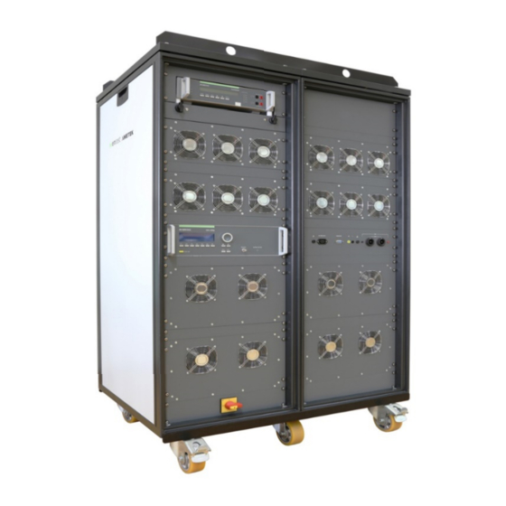
Quick Start and Safety Guide
Automotive
Transient Immunity
Test Generators
200-series
UCS 200Nx
LD 200Nx
VDS 200Qx
PFS 200Nx
MPG 200S21
RCB 200Nx
SNG 200Px
V 1.00
1 / 26
Advertisement
Table of Contents


Need help?
Do you have a question about the 200 Series and is the answer not in the manual?
Questions and answers