Sign In
Upload
Manuals
Brands
Ametek Manuals
Portable Generator
OCS 500N6F
Ametek OCS 500N6F Ringwave Generator Manuals
Manuals and User Guides for Ametek OCS 500N6F Ringwave Generator. We have
2
Ametek OCS 500N6F Ringwave Generator manuals available for free PDF download: Quick Start Manual And Safety Instructions, Manual For Operation
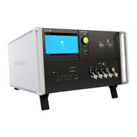
Ametek OCS 500N6F Quick Start Manual And Safety Instructions (88 pages)
Surge, Burst, Damped Oscillatory, Telecom surge generators
Brand:
Ametek
| Category:
Portable Generator
| Size: 3.16 MB
Table of Contents
Table of Contents
3
1 Safety
6
Safety Aspects
6
Safety and Warning Label on the Device
6
Responsibility of the Operator
7
General Hazard
7
Qualification of Personnel
8
Warranty Terms
8
Prohibition of Unauthorized Conversions and Modifications
8
Specific Accessories Required for Safety Reason
8
Procedure in Case of Hazard
8
Temperatures at the Surface
8
Lifting and Carrying Instructions
8
2 Before Activating the Equipment
9
Damage Due to Shipment
9
Power Requirements
10
3-Phase EUT Power Lines
11
Fuse for the EUT Power Supply
11
3 Safety Functions
12
Safety Circuit
12
Safety Circuit for Burst NX and Vsurge NX
12
Safety Circuit on Rack Systems
12
Safety Circuit for Devices of 500-Series
13
Warning Lamp
14
Warning Lamp for Burst NX and Vsurge NX
14
Earthing of Devices
15
Fault Current Protection
15
4 Testing and Precautions
16
Precautions to be Taken
16
Failures and Heavy Strain
16
Coupling Networks
16
Interference to the Environment
17
5 Testing
17
Safety Precautions
17
Danger from EUT
17
6 Quick Start Guide Burst NX8
18
Scope of Delivery
18
Accessories
18
Options
19
Safety Instructions for Installation and Initial Installation
20
Qualifications of the Staff
20
Installation
20
Installation of the Burst NX8
21
Installation Site
21
Voltage Free Switching
21
Grounding and Power Connection
21
Mains Switch and Fuse
22
Connecting the Burst NX8 to the Ground Reference
22
Fuses for EUT with Smaller Nominal Currents
22
EUT Power ON/OFF with Supply Line to Line (400V)
23
Front View (Model-Specific Distinctions)
24
Rear View (Model-Specific Distinctions)
27
Power on the Burst NX8 Generator
30
How to Use the Burst NX8
30
7 Quick Start Guide Vsurge NX15/NX20
31
Scope of Delivery Vsurge NX15
31
Accessories Vsurge NX15
31
Options Vsurge NX15
32
Scope of Delivery Vsurge NX20
32
Accessories Vsurge NX20
32
Options Vsurge NX20
33
Grounding and Power Connection
33
Mains Switch and Fuse
34
Connecting the Vsurge NX15 System to the Ground Reference
34
Safety Circuit, Warning Lamps
35
Safety Circuit
36
Warning Lamp
36
Front View Vsurge NX15
37
Rear View Vsurge NX15
39
Power on the Vsurge NX15 Generator
42
How to Use the Vsurge NX15
42
Front View Vsurge NX20
43
Rear View Vsurge NX20
46
Power on the Vsurge NX20 Generator
49
How to Use the Vsurge NX20
49
8 Quick Start Guide VSS 500N
50
Scope of Delivery
50
Front View
51
Rear View
52
Operation VSS500N Generator
53
Menu Structure
54
Quick Start
54
Technical Data VSS 500N12.X
55
Technical Data VSS 500N12.7
56
Technical Data VSS 500N10
56
9 Quick Start Guide CSS 500N2
57
Scope of Delivery
57
Accessories and Options
57
Front View
58
Rear View
59
Operation CSS500N2 Generator
61
Main Menu
61
Quick Start
62
Technical Data
63
10 Quick Start Guide OCS 500N6 / N6F
64
Models
64
Special Models
64
Front View OCS 500N6.X
65
Rear View OCS 500N6.X
67
Front View OCS 500N6F.X
69
Rear View OCS 500N6F.X
71
Description of the Menus
73
Main Menu OCS 500N6.X
74
Main Menu OCS 500N6F.X
75
Main Menu OCS 500N6F.X
76
Technical Data - Slow Damped Oscillatory as Per IEC 61000-4-18
77
Technical Data - Fast Damped Oscillatory as Per IEC 61000-4-18
77
Technical Data - Ring Wave as Per IEC 61000-4-12
77
11 Quick Start Guide NSG 3150
78
Scope of Delivery NSG 3150
78
General
78
Front View NSG 3150
79
Rear View NSG 3150
80
The Standard User Interface (SUI)
80
Installation
81
Installation of an EUT Power Switch
81
User Warnings Generator
81
Dangers Concerning the EUT
81
11.10. Technical Data
82
Coupling/Decoupling Network CDN 3153-S63.1
83
12 How to Use a Nextgen Device
84
General Safety Instructions
84
Front Connections
84
Rear Connections
84
Control Elements
85
Home Screen
85
Quick Start
85
Pulse Settings
86
Info: Pulse Settings
86
Starting a Test
87
The Test Run
87
Info: Button Status Indicators
87
13 Maintenance, Adjustments, Replacement of Parts
88
Disposal of Devices
88
Calibration and Verification
88
Advertisement
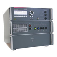
Ametek OCS 500N6F Manual For Operation (80 pages)
The Damped Oscillatory and Ring Wave generator in one box
Brand:
Ametek
| Category:
Test Equipment
| Size: 3.3 MB
Table of Contents
Table of Contents
3
General
5
Purpose
5
Safety Label on the Device
5
Standards Covered by OCS 500N6 / N6F Generators
6
Models and Options
6
Special Models
7
Operating Functions
8
OCS 500N6.X Models
8
Front View OCS 500N6.X
8
Rear View OCS 500N6.X
10
OCS 500N6F Models
12
Front View OCS 500N6F.X
12
Rear View OCS 500N6F.X
14
Operation
16
Description of the Menus
16
Menu Structure
17
Main Menu OCS 500N6.X
18
Main Menu OCS 500N6F.X
19
Phase Synchronization in 3-Phase System
20
Service
21
Setup
23
Test Equipment OCS 500 Nx
24
Assembling OCS 500N6
24
Assembling OCS 500N6Fx
25
Technical Data
26
Slow Damped Oscillatory as Per IEC 61000-4-18
26
Fast Damped Oscillatory as Per IEC 61000-4-18
28
RINGWAVE Immunity Requirements as Per ANSI C 62.41 (IEC 61000-4-12)
29
General Specifications OCS 500N6.X
30
General Specifications OCS 500N6F.X
31
Damped Oscillatory 100 Khz or 1 Mhz as Per IEC 61000-4-18
32
Operation
32
Quick Start
33
Standard Test Routines
34
User Test Routines
36
Coupling Decoupling Network
37
Coupling/Decoupling Network for Ac/DC Power Lines
37
Coupling to Signal- and Datalines
38
Ri Setting for Slow Damped Oscillatory Wave 100 Ω or 200 Ω
39
Menu Damped Osc. 1Mhz EXT
40
Coupling as Per IEC 60255 with CNV 508 N4
40
Quick Start
41
Standard Test Routines
41
User Test Routines
43
Fast Damped Oscillatory 3 Mhz, 10 Mhz or 30 Mhz as Per IEC 61000-4-18
44
Operation
44
Quick Start
45
Standard Test Routines
46
User Test Routines
48
Coupling Decoupling Network
49
Coupling/Decoupling Network for Ac/DC Power Lines
49
Coupling to Signal and Datalines
49
Ring Wave
50
Operation
50
Quick Start
51
Standard Test Routine
52
User Test Routines
55
Ringwave and Damped Oscillatory Pulse Generation
56
Coupling Decoupling Network
57
Coupling to Ac / DC Power Supply Lines
57
Coupling to Signal- and Datalines
58
Test Set-Up
59
Damped Oscillatory Magnetic Field as Per IEC 61000-4-10
60
General
60
Menu Damped Osc. Wave 1 Mhz Magnetic Field (MF)
61
Maintenance
62
General
62
Test Set- up
62
Calibration and Verification
63
Factory Calibration
63
Guideline to Determine the Calibration Period of AMETEK CTS Instrumentation
63
Calibration of Accessories Made by Passive Components Only
63
Periodically In-House Verification
63
Verification Ringwave
64
Verification Parameter
64
Verification Damped Oscillatory Wave
65
Verification Parameter Slow Damped Oscillatory Wave
65
Verification Setup
66
Verification Parameter Fast Damped Oscillatory Wave
67
Verification Damped Oscillatory Wave 100 / 1000 Khz Magnetic Field
71
Verification Parameter
71
Delivery Groups
72
Basic Equipment
72
Accessories and Options
72
USB Interface
74
Optical Interface
74
Appendix
75
Declaration of CE-Conformity
75
OCS 500 N6- General Diagram
77
OCS 500 N6F- General Diagram 1-Phase Devices
78
OCS 500 N6F- General Diagram 3-Phase Devices
79
OCS 500N6 1-Phase Operating with 3-Phase Devices
80
Advertisement
Related Products
Ametek OCS500N6F.1
Ametek OCS500N6F.2
Ametek OCS500N6F.3
Ametek OCS500N6F.4
Ametek OCS 500 N6
Ametek OCS500 N6.11
Ametek OCS500N6.5
Ametek OCS500N6.6
Ametek OCS500N6.8
Ametek OCS500N6.7
Ametek Categories
Measuring Instruments
Test Equipment
Power Supply
Controller
Laboratory Equipment
More Ametek Manuals
Login
Sign In
OR
Sign in with Facebook
Sign in with Google
Upload manual
Upload from disk
Upload from URL