
Related Manuals for Ametek MX Series


Summary of Contents for Ametek MX Series
- Page 1 MX Series AC and DC Power Source User Manual 7003-960 Rev BE www.programmablepower.com...
- Page 2 User Manual – Rev BE AMETEK Programmable Power User's Manual California Instruments - AC Power Source By AMETEK Programmable Power. Models COVERED IN THIS MANUAL: MX22.5-1 MX22.5-3 MX22.5-3Pi MX30-1 MX30-3 MX30-3Pi MX45-1 MX45-3 MX45-3Pi MX60-3 MX60-3Pi (-MB) MX90-3 MX90-3Pi (-MB)
- Page 3 AMETEK Programmable Power About AMETEK AMETEK Programmable Power, Inc., a Division of AMETEK, Inc., is a global leader in the design and manufacture of precision, programmable power supplies for R&D, test and measurement, process control, power bus simulation and power conditioning applications across diverse industrial segments.
- Page 4 User Manual – Rev BE AMETEK Programmable Power Hazardous voltages may be present when covers are removed. Qualified personnel must use extreme caution when servicing this equipment. Circuit boards, test points, and output voltages also may be floating above (below) chassis ground.
- Page 5 Use safety glasses during open cover checks to avoid personal injury by any sudden component failure. Neither AMETEK Programmable Power Inc., San Diego, California, USA, nor any of the subsidiary sales organizations can accept any responsibility for personnel, material or inconsequential injury, loss or damage that results from improper use of the equipment and accessories.
- Page 6 User Manual – Rev BE AMETEK Programmable Power Safety Symbols MX Series...
- Page 7 AMETEK in accordance with the return procedure specified below. AMETEK will, at its expense, deliver the repaired or replaced Product or parts to the Buyer. Any warranty of AMETEK will not apply if the Buyer is in default under the Purchase Order Agreement or where the Product or any part thereof: is damaged by misuse, accident, negligence or failure to maintain the same as specified or required by AMETEK;...
- Page 8 User Manual – Rev BE AMETEK Programmable Power This page is intentionally blank MX Series...
-
Page 9: Table Of Contents
Power Requirements ..................47 Mechanical Installation ..................48 AC Input Connections and Wiring ............... 49 AC On/Off Circuit Breaker on MX Series Front Panel..........54 Output Connections ..................56 Connectors - Rear Panel ..................73 Multiple Cabinet System Configurations (incl. –MB) ..........82 Multiple Cabinet System - Power Up/Down Procedures .......... - Page 10 User Manual – Rev BE AMETEK Programmable Power Routine Output Calibration ................214 Non-Routine Calibration .................. 226 7. Service ....................... 234 Cleaning ......................234 General ......................234 Basic Operation ....................234 Advanced Troubleshooting................236 Factory Assistance ..................239 Fuses ......................240 Firmware Updates ..................
- Page 11 Figure 3-1: The MX45 Power Source ....................48 Figure 3-2: Location of AC Input and Chassis Ground Connection - Front View, Access Panel Removed ..50 Figure 3-3: MX Series AC Input Connection Diagram (Rear view) ............52 Figure 3-4: Rear Panel ........................55 Figure 3-5: External Sense Cable Shield Connection to Chassis Ground ............
- Page 12 Figure 4-45: Switching Waveforms in a Transient List ................185 Figure 4-46: START/VIEW TRANSIENT SEQUENCE Menu ..............186 Figure 5-1: MX Series Functional Block Diagram .................. 188 Figure 5-2: MX Series Detailed Block Diagram..................193 Figure 5-3: Power Module Detailed Block Diagram ................194 Figure 5-4: Power Module Layout ......................
- Page 13 User Manual – Rev BE AMETEK Programmable Power Figure 9-42: Emergency Test ......................308 Figure 9-43: Application Screen ......................310 Figure 9-44: Watt-Hour Meter Screen ....................310 Figure 9-45: WH-Meter Screen with Function Active................311 Figure 9-46: REGENERATE CONTROL Screen ..................314...
- Page 14 Table 6-1: Calibration Load Values ....................210 Table 6-2: Measurement Calibration Table ..................213 Table 6-3: Output Calibration Table – MX Series I ................224 Table 6-4: Output Calibration Table – MX Series II ................225 Table 6-5: Current Limit Calibration ....................230 Table 6-6: Programmable Z Adjustment Pots ..................
-
Page 15: Introduction
1.1 General Description The MX Series AC and DC power source systems are high efficiency, floor standing AC and DC power sources that provide a precise output with low distortion. Available voltage ranges are 150 Vac, 300 Vac and an optional 400 Vac in AC mode and 200 Vdc and 400 Vdc in DC mode. - Page 16 User Manual – Rev BE AMETEK Programmable Power control interfaces and command syntax. The programming manual is provided on the same CDROM as this user manual. MX Series...
-
Page 17: Different Model Series
Series I products. The part number is shown on the model / serial number tag on the back of the MX series. All Series II will have a firmware revision of 4.0 or higher. The firmware revision is displayed briefly at power up on the LCD display and can also be queried over the bus by using the *IDN? command. -
Page 18: Specifications
User Manual – Rev BE AMETEK Programmable Power 2. Specifications Specifications shown are valid over an ambient temperature range of 25 ± 5° C and apply after a 30-minute warm-up time. Unless otherwise noted, all specifications are per phase for sine wave output into a resistive load. For three phase configurations or mode of operation, all specifications are for Line to Neutral (L-N) and phase angle specifications are valid under balanced load conditions only. -
Page 19: Electrical
User Manual – Rev BE AMETEK Programmable Power 2.1 Electrical 2.1.1 Input Single Cabinet M odels Parameter M X 22.5 M X 30 M X 45 208 V LL ±10% 230 V LL ±10% Line V oltage: 380 V LL ±10% (3 phase, 3 wire + ground (PE)) 400 V LL ±10%... - Page 20 User Manual – Rev BE AMETEK Programmable Power M ultiple Chassis Systems M X 60 M X 90 M X 135 M X 180 M X 225 M X 270 Parameter (2 M X 30 (2 M X 45 (3 M X 45...
- Page 21 User Manual – Rev BE AMETEK Programmable Power 2.1.2 Output NOTE: All specifications are for AC and DC unless otherwise indicated. Individual Cabinet M odels Output Parameter M X 22.5 M X 30 M X 45 M odes Std Controller...
- Page 22 User Manual – Rev BE AMETEK Programmable Power Individual Cabinet M odels Output Parameter M X 22.5 M X 30 M X 45 0.5 % FS @ > 100 Hz Line Regulation: 0.1% for 10% input line change DC Offset V oltage: <...
- Page 23 User Manual – Rev BE AMETEK Programmable Power Individual Cabinet M odels Output Parameter M X 22.5 M X 30 M X 45 V Hi: 225 A V Hi: 450 A M X 22.5-3 / MX 22.5-3Pi, per M X 30-3 / MX 30-3Pi / MX 45-3 / MX 45-3Pi, per phase...
- Page 24 < 1.00 % @ 66 - 500 Hz < 1.50 % @ > 500 Hz 1 The distortion specification for the MX Series is valid for pure (inductance < 12 uH) resistive load conditions and using a 30 K Hz Low Pass filter on distortion meter.
- Page 25 User Manual – Rev BE AMETEK Programmable Power M ultiple Cabinet Systems Output M X 60 M X 90 M X 135 M X 180 M X 225 M X 270 Parameter Line Regulation: 0.1% for 10% input line change DC Offset V oltage: <...
- Page 26 User Manual – Rev BE AMETEK Programmable Power M ultiple Cabinet Systems Output M X 60 M X 90 M X 135 M X 180 M X 225 M X 270 Parameter ±0.25 % for –FC option Phase (3 phase mode)
-
Page 27: Figure 2-1: Voltage / Current Rating Chart For 150/300 V Ac Ranges
User Manual – Rev BE AMETEK Programmable Power NOTE: Output specifications apply below the Current / Voltage rating lines shown in the V/I rating charts below. Figure 2-1: Voltage / Current Rating Chart for 150/300 V AC Ranges. Figure 2-2: Voltage / Current Rating Chart for 150/300 V AC Ranges – Max Rating. - Page 28 User Manual – Rev BE AMETEK Programmable Power 2.1.3 AC Measurements Measurement specifications apply to MX22.5-3 / MX22.5-3Pi / MX30-3 / MX30-3Pi / MX45-3 or MX45-3Pi in three-phase mode. See notes for other models and configurations. Parameter Range Accuracy (±) Resolution 0.01 to 81.91 Hz...
- Page 29 User Manual – Rev BE AMETEK Programmable Power 2.1.6 Harmonic Measurements (Pi controller) Harmonic measurement specifications apply to MX22.5, MX30-3, MX45-3, MX 22.5- 3Pi, MX30-3Pi and MX45-3Pi in three-phase mode. See notes for other models and configurations. Parameter Range Accuracy (±)
- Page 30 User Manual – Rev BE AMETEK Programmable Power Response time is 10 ms (typical) Bi-directional serial interface ,9 pin D-shell connector Handshake: CTS, RTS Data bits: 7, 8 Stop bits: 1,2 Baud rate: 9600 to 115,200 bps RS232C Interface: Syntax: IEEE 488.2 and SCPI.
-
Page 31: Mechanical
User Manual – Rev BE AMETEK Programmable Power 2.1.8 Unit Protection Parameter Description In-line fast acting fuses. Check fuse rating in Service and M aintenance section. Ratings will depend on AC input configuration settings. Input Over current: Circuit breaker for LV supply. -
Page 32: Environmental
User Manual – Rev BE AMETEK Programmable Power Environmental Parameter Specification 0° to +35° C. (Except in CP mode). Operating Temp: +32° to +104° F. -40° to +85 °C. Storage Temp: -40° to +185° F. < 2000 meters A ltitude: 0-95 % RAH, non-condensing maximum for temperatures up to 31°C decreasing linearly to 50% at 40°C. -
Page 33: Front Panel Controls
User Manual – Rev BE AMETEK Programmable Power 2.5 Front Panel Controls Controls: Allows continuous change of all values including output calibration and range change. Shuttle knob: A conventional decimal keypad facilitates quick entry of numerical values such as voltage, current limit, etc. -
Page 34: Special Features And Options
User Manual – Rev BE AMETEK Programmable Power 2.6 Special Features and Options Controller Features Switches between 1 and 3 phase outputs. This mode is available on models M X 30-3Pi and M X 45-3Pi only. M ode: Up to three units can be paralleled in a three-phase configuration (with one master controller and one or two auxiliary units). - Page 35 NOTE: Do not misplace the 2 keys provided, as no duplicates are available from A M ETEK . If lost, the ES switch must be replaced. In that case, contact AM ETEK Programmable Power repair department at: (repair.ppd@ametek.com). Increases maximum output frequency to 905 Hz.
- Page 36 User Manual – Rev BE AMETEK Programmable Power 2.6.1 -HV Option Specifications The -HV option provides an AC only output range of 0 to 400 Vac L-N. Specifications unique to the -HV option are shown in the table below. Output Parameter M X 22.5...
- Page 37 User Manual – Rev BE AMETEK Programmable Power 2.6.2 -XV Option Specifications Consult factory for -XV option specifications. 2.6.3 -HF Option Specifications The -HF option extends the maximum available output frequency from 819 Hz to 905 Hz. Some restrictions are in effect at this increased output frequency level.
-
Page 38: Figure 2-3 -Hf Option Voltage Frequency Rating 300V Range
User Manual – Rev BE AMETEK Programmable Power Figure 2-3 -HF Option Voltage Frequency Rating 300V range Figure 2-4 -HF Option Voltage Frequency Rating 150V range MX Series... - Page 39 User Manual – Rev BE AMETEK Programmable Power 2.6.4 -LF Option Specifications The -LF option limits the maximum available output frequency to 500 Hz. All other specifications of the MX45 system remain unchanged if this option is installed. 2.6.5 WHM Option Specifications...
- Page 40 User Manual – Rev BE AMETEK Programmable Power 2.6.6 SNK (AC or DC) Option Specifications The –SNK or current sink option enables the MX power source to sink current from the unit under test. This mode of operation is particularly useful when testing grid- tied products that feed energy back onto the grid.
-
Page 41: Supplemental Specifications
User Manual – Rev BE AMETEK Programmable Power 2.7 Supplemental Specifications Supplemental specifications are not warranted and generally reflect typical performance characteristics. These characteristics have been checked on a type test basis only and are not verified on each unit shipped. They are provided for reference only. - Page 42 2.7.3 Output Noise Spectrum The MX series is a switching power supply and as such will have a certain amount of switching noise at its output. While the overall RMS noise is specified, the specific noise spectrum will differ slightly from unit to unit. The information provided in this section is for reference only.
-
Page 43: Figure 2-5 Mx Output Filter Option Schematic
User Manual – Rev BE AMETEK Programmable Power Figure 2-5 MX Output Filter Option Schematic MX Series... -
Page 44: Figure 2-6 Mx45 Output Noise 10 Khz - 1 Mhz
User Manual – Rev BE AMETEK Programmable Power MX Series... -
Page 45: Figure 2-7 Mx45 Output Noise 10 Khz - 1 Mhz With Optional Filter
User Manual – Rev BE AMETEK Programmable Power MX Series... - Page 46 User Manual – Rev BE AMETEK Programmable Power BLANK PAGE MX Series...
-
Page 47: Unpacking And Installation
Kg) to 1150 lbs (522 Kg), depending on model. Obtain adequate help when moving the unit. Make sure the location (floor) in which the MX Series unit(s) will be installed can support the weight of the unit(s). 3.2 Power Requirements... -
Page 48: Mechanical Installation
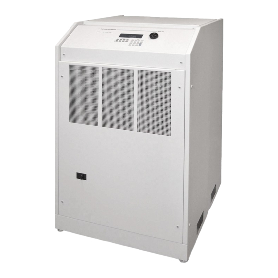
User Manual – Rev BE AMETEK Programmable Power Figure 3-1: The MX45 Power Source 3.3 Mechanical Installation MX Series... -
Page 49: Ac Input Connections And Wiring
Figure 3-2 for details. No wiring for AC input connections is provided with the MX Series and must be provided by the end user or installer. Input wiring should be entered through the right-hand side (when facing the back of the MX cabinet, see Figure 3-4) wire access opening located at the rear bottom of the MX chassis. -
Page 50: Figure 3-2: Location Of Ac Input And Chassis Ground Connection - Front View, Access Panel Removed
User Manual – Rev BE AMETEK Programmable Power Figure 3-2: Location of AC Input and Chassis Ground Connection - Front View, Access Panel Removed NOTE: DO NOT USE THE NEUTRAL CONNECTION OF A 3 PHASE Y AC POWER CONNECTION IN PLACE OF A TRUE EARTH GROUND CONNECTION. - Page 51 User Manual – Rev BE AMETEK Programmable Power DELTA INPUT WIRING CONNECTION ONLY. NO NEUTRAL CONNECTION IS REQUIRED OR PROVIDED. DO NOT USE AN AC NEUTRAL CONDUCTOR FOR GROUNDING THE CHASSIS. USE A SEPARATE PROTECTIVE EARTH GROUND CONNECTION ONLY. MX Series...
-
Page 52: Figure 3-3: Mx Series Ac Input Connection Diagram (Rear View)
User Manual – Rev BE AMETEK Programmable Power Figure 3-3: MX Series AC Input Connection Diagram (Rear view) MX Series... -
Page 53: Table 3-1: Suggested Input Wiring Sizes For Each Mx Cabinet
User Manual – Rev BE AMETEK Programmable Power The input power cables, and protective circuit breaker used must be specified to handle the input current and input voltage of the power source and must conform to local electrical codes. Consult a qualified electrician prior to installation. -
Page 54: Ac On/Off Circuit Breaker On Mx Series Front Panel
It is important to understand the purpose and operation of the On/Off circuit breaker of the MX Series located on the lower left side of the front panel. This is a 2A rated breaker that is used to engage and protect the LV Power supply of the MX chassis only. -
Page 55: Figure 3-4: Rear Panel
User Manual – Rev BE AMETEK Programmable Power Figure 3-4: Rear Panel MX Series... -
Page 56: Output Connections
User Manual – Rev BE AMETEK Programmable Power 3.6 Output Connections 3.6.1 Output Wiring The output terminal blocks, TB1A and TB1B are located at the front of the unit behind the bottom access panel. See Figure 3-2 for details. Three phase output line connections are made to terminal block TB1A. The phase outputs are labeled A, B and C. -
Page 57: Figure 3-5: External Sense Cable Shield Connection To Chassis Ground
User Manual – Rev BE AMETEK Programmable Power Figure 3-5: External Sense Cable Shield Connection to Chassis Ground NOTE: The output of the power source is isolated from the input line and floating with respect to chassis ground. If needed, either side (HI or LO) may be grounded. - Page 58 User Manual – Rev BE AMETEK Programmable Power NOTE: Use high temperature rated wire. Always consult the National Electrical Code and/or local code regulations for proper rating and size of wire cabling prior to installation. MX Series...
-
Page 59: Table 3-3: Output Terminal Connections
The correct standard size Allen wrenches for connecting output wiring to TB1A and/or TB1B are supplied with each MX in the ship kit. Look for a brown envelope. If the correct tools cannot be found, contact AMETEK Programmable Power customer service at repair.ppd@ametek.com. -
Page 60: Figure 3-6: Location Of Output Terminals (Front View)
User Manual – Rev BE AMETEK Programmable Power Figure 3-6: Location of Output Terminals (Front view) 3.6.3 MX22.5-1, MX45-1, MX30-1, MX22.5-3Pi, MX30-3Pi and MX45-3Pi 1 ø mode Output Wiring Diagram Figure 3-7 shows the required output connections for a MX30-1, MX45-1, MX30- 3Pi or MX45-3Pi in single-phase mode output configuration (rear-view perspective). -
Page 61: Figure 3-7: Mx 22.5-1, Mx30-1 / Mx45-1 Output Wiring (Rear View)
User Manual – Rev BE AMETEK Programmable Power Figure 3-7: MX 22.5-1, MX30-1 / MX45-1 Output Wiring (Rear view) MX Series... - Page 62 User Manual – Rev BE AMETEK Programmable Power 3.6.4 MX30-3, MX45-3, MX30-3Pi and MX45-3Pi 3ø mode Output Wiring Diagram Figure 3-8 shows the required output connections for a MX30-3, MX45-3 three phase or an MX30-3Pi and MX45-3Pi in three-phase mode output configuration (rear-view perspective).
-
Page 63: Figure 3-8: Mx 22.5-3, Mx30-3 / Mx45-3 Output Wiring (Rear View)
User Manual – Rev BE AMETEK Programmable Power Figure 3-8: MX 22.5-3, MX30-3 / MX45-3 Output Wiring (rear view) MX Series... - Page 64 User Manual – Rev BE AMETEK Programmable Power 3.6.5 MX60 or MX90 Output Wiring Diagram Figure 3-9 shows the required output connections for a MX60-3 or MX90-3 three phase output configuration (rear- view perspective). Always disconnect all input power from the MX60 or MX90 before removing the front panel cover that provides access to the input and output terminal connections.
-
Page 65: Figure 3-9: Mx60, Mx60-Mb, Mx90 Or Mx90-Mb Output Wiring (Rear View)
User Manual – Rev BE AMETEK Programmable Power Figure 3-9: MX60, MX60-MB, MX90 or MX90-MB Output Wiring (rear view) MX Series... -
Page 66: Figure 3-10: Two Mx's In Clock And Lock Mode Output Wiring (Rear View)
User Manual – Rev BE AMETEK Programmable Power Figure 3-10: Two MX's in Clock and Lock Mode Output Wiring (rear view) MX Series... - Page 67 User Manual – Rev BE AMETEK Programmable Power 3.6.6 MX135 Output Wiring Diagram Figure 3-11 shows the required output connections for a MX135-3Pi or MX135-3Pi-MB three phase output configuration (rear-view perspective). Always disconnect all input power from the MX135 before removing the front panel cover that provides access to the input and output terminal connections.
-
Page 68: Figure 3-11: Mx135 Or Mx135-Mb Output Wiring (Rear View)
User Manual – Rev BE AMETEK Programmable Power Figure 3-11: MX135 or MX135-MB Output Wiring (Rear view) MX Series... -
Page 69: Figure 3-12: Three Mx's In Clock And Lock Mode - Output Wiring (Rear View)
User Manual – Rev BE AMETEK Programmable Power Figure 3-12: Three MX's in Clock and Lock mode - Output Wiring (rear view) MX Series... - Page 70 User Manual – Rev BE AMETEK Programmable Power 3.6.7 MX180, MX225, and MX270 Output Wiring Diagram Figure 3-11 shows the required output connections for a MX180-3Pi through MX270-3Pi three phase output configuration (rear-view perspective). For MX180, only 4 cabinets are used and for MX225 only 5 but otherwise the wiring diagrams are the same so only the complete MX270-3Pi configuration is shown.
-
Page 71: Figure 3-13: Mx180, Mx225 Or Mx270 Output Wiring (Rear View)
User Manual – Rev BE AMETEK Programmable Power Figure 3-13: MX180, MX225 or MX270 Output Wiring (rear view) MX Series... - Page 72 User Manual – Rev BE AMETEK Programmable Power 3.6.8 Multi-Chassis Output Connections If two or more MX chassis are used to form a single power system, the outputs of all chassis need to be combined (paralleled by phase). This can be done directly at the EUT if convenient or using the provided heavy-duty terminal blocks.
-
Page 73: Connectors - Rear Panel
Several connectors are located along the top rear covers. These connectors are in a recessed area to protect them from shipment damage. 3.7.1 System Interface WARNING: The system interface connectors are for use with AMETEK Programmable Power supplied cables, and only between California Instruments equipment. MX Series... - Page 74 User Manual – Rev BE AMETEK Programmable Power The Clock and Lock BNC connectors located on the rear panel are used to synchronize and control the phase shift between the three outputs when 3 units are operating as a three-phase clock and lock system. This mode of operation requires the -LKM (on Master unit) and -LKS (on Auxiliary units) options.
-
Page 75: Table 3-4: System Interface Connectors
User Manual – Rev BE AMETEK Programmable Power P8 / P9 Description DC: DC mode control INP OFF: Input power control A ERR HI: Error Signal Phase A, high B ERR LO: Error Signal Phase B, low C ERR HI: Error Signal Phase C, high Table 3-4: System Interface Connectors 3.7.2... -
Page 76: Table 3-7: External Sense Connector
User Manual – Rev BE AMETEK Programmable Power Phase C sense Neutral sense Table 3-7: External Sense Connector MX Series... -
Page 77: Table 3-8: Rs232 Connector Pin-Out - Mx With Rs232 And Usb
PC. With these MX models, a special 13 foot (4 meters) cable is supplied in the MX Series ship-kit. The wiring diagram for this cable is shown below in case a longer cable needs to be constructed. Alternatively, a generic straight thru DB9 male to DB9 female cable can be used to extend the supplied cable. -
Page 78: Figure 3-15: Rs232C Cable For Pc Connection Wiring Diagram - Mx Without Usb
User Manual – Rev BE AMETEK Programmable Power Figure 3-15: RS232C Cable for PC Connection Wiring Diagram – MX without USB. MX Series... -
Page 79: Figure 3-16: Usb Connector Pin Orientation
User Manual – Rev BE AMETEK Programmable Power 3.7.6 USB Interface A standard USB Series B device connector is located on the rear panel for remote-control. A standard USB cable between the AC Source and a PC or USB Hub may be used. -
Page 80: Figure 3-17: Lan Interface Connector
The serial tag is located on the rear panel of the unit. For information on how to set up a network connection or a direct PC connection using the LAN interface, refer to the MX Series Programming Manual P/N 7003- Figure 3-17: LAN Interface Connector 961 distributed in Adobe PDF format on CD ROM CIC496. -
Page 81: Figure 3-18: Emergency Switch (Es Option) Shutoff Interconnect On -Mb Systems
User Manual – Rev BE AMETEK Programmable Power 3.7.8 ES Option - Emergency Switch Interconnect for –MB systems – BNC Except for MX units shipped January 2017 and later, an optional BNC connector is located on the rear panel for connecting multiple chassis, each having a controller and an emergency shut off switch (-ES option). -
Page 82: Multiple Cabinet System Configurations (Incl. -Mb)
User Manual – Rev BE AMETEK Programmable Power Name Description 24V DC M aster Select. C onnection is made to M aster Chassis only. 24V DC /10mA to set a SLA V E M aster unit into AUX mode. SLAV E Common. -
Page 83: Figure 3-20: Multi-Cabinet Dip Switch Location And Setting
User Manual – Rev BE AMETEK Programmable Power In addition to disabling the controller if present (as described above), the DIP switch (S1) located on the GPIB / RS232C / IO assembly in the auxiliary cabinets. (Requires removal of the top cover). The correct switch settings are shown below. -
Page 84: Multiple Cabinet System - Power Up/Down Procedures
User Manual – Rev BE AMETEK Programmable Power 3.9 Multiple Cabinet System - Power Up/Down Procedures For all multi-cabinet MX Series configurations (MX60, MX90, MX135, MX180, MX225 and MX270), the following Power Up (Turn on) and Power Down (Turn off) procedures should be observed. -
Page 85: Clock And Lock Configurations
AMETEK Programmable Power 3.10 Clock and Lock Configurations The MX Series may optionally be equipped for clock and lock mode of operation. This mode is a special form of Master/Auxiliary, which requires each chassis to have its controller. As such, it is possible to create 2, 3, 6 or 9 phase power systems using 2 to 3 MX chassis. -
Page 86: Table 3-13: Clock And Lock Initialization Settings
User Manual – Rev BE AMETEK Programmable Power 3.10.2 Clock/Lock Initialization Settings The mode of operation of the MX-LKS auxiliary unit is determined by the Clock mode set in the PROGRAM2 screen. Since most clock and lock systems are permanently used in this configuration, the clock mode can be set to EXT (External) at power on by using the INITIAL SETUP3 screen. - Page 87 User Manual – Rev BE AMETEK Programmable Power To set up a GPIB remote-controlled clock and lock systems, the GPIB addresses for the individual MX's must be set to different address values in the UTILITY1, GPIB/RS232 SETUP screen. NOTE: This mode of operation is not supported by the VIRTUAL PANELS Windows software supplied with each MX unit.
-
Page 88: Basic Initial Functional Test
User Manual – Rev BE AMETEK Programmable Power 3.11 Basic Initial Functional Test CAUTION: Work carefully when performing these tests; hazardous voltages are present on the input and output during this test. Refer to Figure 3-21 for the required functional test set up. Proceed as follows... - Page 89 User Manual – Rev BE AMETEK Programmable Power Select the MEASUREMENT 1 screen by pressing the MEAS button. The output voltage, current and power will be displayed. For three phase configurations, use the PHASE button to select the øABC display mode. This will show the voltage, current and power for all three phases.
-
Page 90: Figure 3-21: Functional Test Setup
User Manual – Rev BE AMETEK Programmable Power Figure 3-21: Functional Test Setup. MX Series... -
Page 91: Remote Inhibit / Remote Shutdown
On units with firmware rev 0.27 or lower, this input level mode selection is not available. MX Series I When set to HIGH, an active low TTL level or a contact closure is required to enable the output relay of the MX. - Page 92 User Manual – Rev BE AMETEK Programmable Power turning on the MX master unit. During initialization, the RI connection must be OPEN or initialization will be halted with the message WARNING FOR AUXILIARY displayed on the LCD screen. MX Series...
-
Page 93: Junction Box Accessory
User Manual – Rev BE AMETEK Programmable Power 3.13 Junction Box Accessory An optional wiring junction box (P/N 7003-416-1) is available which may be used to connect the outputs of 2 to 6 MX cabinets together. The junction box also has a protective ground connection, which MUST be connected to a suitable protective earth ground. -
Page 94: Output Filter Box Accessory
User Manual – Rev BE AMETEK Programmable Power Figure 3-22: 7003-416-1 Output Junction Box DIMENSIONS 7003-416-1 OUTPUT JUNCTION BOX: Parameter Dimension in Inches Dimension in mm Chassis Dimension W x L x H 12.125 “ x 16.125” x 4.125” 308 x 410 x 105 mm Feet height: 0.875... -
Page 95: Figure 3-23: 7003-424-1 Output Noise Filter Box
User Manual – Rev BE AMETEK Programmable Power To compensate for the voltage drop across the filter, the external sense connections can be made at the load (load side of the filter). NOTE: The filter box chassis must be connected to earth ground. -
Page 96: Fuse Box Accessory
User Manual – Rev BE AMETEK Programmable Power 3.15 Fuse Box Accessory An Output Fuse Box (P/N 7003-426-1) is provided with MX systems consisting of more than 2 cabinets. This fuse box provides protection against excessive current circulating between amplifiers in different chassis in case of a system malfunction. -
Page 97: Figure 3-24: 7003-426-1 Output Fuse Box
User Manual – Rev BE AMETEK Programmable Power Figure 3-24: 7003-426-1 Output Fuse Box DIMENSIONS 7003-426-1 OUTPUT FUSE BOX: Parameter Dimension in Inches Dimension in mm Chassis Dimension W x L x H 12.125 “ x 16.125” x 4.125” 308 x 410 x 105 mm Feet height: 0.875... -
Page 98: Front Panel Operation
4. Front Panel Operation 4.1 Tour of the Front Panel The MX Series with type P or type Pi have identical front panels although some of the keys found on the front panel are only used by MX models with the 3Pi controller. - Page 99 SYST:REM command. Any time the REMOTE\LAN LED is lit, the front panel of the MX Series unit is disabled. There is no LOCAL button that allows the user to regain control of the front panel.
-
Page 100: Figure 4-1. Status And Fault Leds (Mx45 Front Panel Shown)
User Manual – Rev BE AMETEK Programmable Power Figure 4-1. Status and Fault LEDs (MX45 front panel shown) MX Series... -
Page 101: Figure 4-2: Shuttle Knob
MODE DESCRIPTION IMMEDIATE mode Any time the ENTER key is pressed, the MX Series returns to its normal mode of operation. In this mode, changes made with the shuttle knob, or the data entry keypad will take immediate effect. The IMMEDIATE... -
Page 102: Figure 4-3: Function Keypad
PROG, WAVE, and MEAS keys, respectively. A map of the Main menus is provided on the next few pages. There are three top level menus in the MX Series. PROG The PROG key is a shortcut to access the PROGRAM menu directly. - Page 103 User Manual – Rev BE AMETEK Programmable Power The WAVEFORM screen is used to select a user defined arbitrary waveform. (3Pi controller only) MEAS The MEAS key is a shortcut to access the MEASUREMENT screen directly. The MEASUREMENT screen is one of the most frequently used screens.
-
Page 104: Figure 4-4: Entering Values From The Decimal Keypad
User Manual – Rev BE AMETEK Programmable Power 4.1.5 DECIMAL KEYPAD The decimal keypad may be used to enter any numeric parameter required in any of the menu fields. Several fields accept input from either the keypad or the knob. Data entered from the keypad is normally accepted once the ENTER key is pressed unless the front panel mode is in the SET mode. -
Page 105: Figure 4-6: Cursor Down Key Movement
To ease reading of the displayed information, most screens are widely spaced. A sample of the main menu 1 screen that appears when the MX Series source is powered up is shown in Figure 4-7. -
Page 106: Figure 4-7: Main Menu 1 Screen
User Manual – Rev BE AMETEK Programmable Power selection followed by pressing the ‘ENTER’ key. Alternatively, the MENU key may be pressed to move to the MENU 2 screen. The present cursor position is always shown with an inverse bar. The cursor is located on the ‘MORE’... -
Page 107: Menu Structure
AMETEK Programmable Power 4.2 Menu Structure The next few pages show a map of the available menus in the MX Series. There are three main level (level 1) menus from which all other menus can be reached. Frequently used (level 2) menus have a short cut key that provides direct access. - Page 108 APPLICATIONS The APPLICATIONS menu provides access to the optional firmware application programs that may be installed in the MX Series AC source. SETUP REGISTERS The SETUP REGISTERS menu allows complete instrument settings and transient list programs to be saved to nonvolatile memory.
- Page 109 User Manual – Rev BE AMETEK Programmable Power OUTPUT IMPEDANCE The OUTPUT IMPEDANCE menu provides control of the AC source output impedance. (MX30-3Pi or MX45-3Pi model only) MEASUREMENT CAL The MEASUREMENT CAL menu allows for calibration of the AC source measurement system.
- Page 110 User Manual – Rev BE AMETEK Programmable Power 4.2.2 Overview of Menu 1 level 1 level 2 level 3 PROGRAM PROGRAM1 VOLTAGE FREQ VOLT RANGE CURR LIMIT MORE PROGRAM2 PHASE CLOCK MODE VOLT MODE DC OFFSET START ø MEASUREMENTS MEASUREMENTS1...
- Page 111 User Manual – Rev BE AMETEK Programmable Power MORE USER WAVE MX Series...
- Page 112 User Manual – Rev BE AMETEK Programmable Power 4.2.3 Overview of Menu 2 and 3 level 1 level 2 level 3 MENU 2 ADVANCE HARMONICS/TRACE MEAS. ANALYSIS FUNCTION VIEW DATA MODE SCALE TRIG MODE TRIG SOURCE TRIG PHASE TRIG DELAY...
-
Page 113: Figure 4-9: Program Menu
User Manual – Rev BE AMETEK Programmable Power OUTPUT RESISTIVE CONFIG SETUP NO. OUTPUT IMPEDANCE INDUCTIVE MS704 VOLT ALC SET MINIMUM PREVIOUS SCREEN SYSTEM CONFIG SETUP Series II only MANUAL OPTn CONFIG SETUP Series II only Series I only MEASUREMENT... - Page 114 User Manual – Rev BE AMETEK Programmable Power by pressing the PROG key in the FUNCTION keypad • The PROGRAM menu is used to change output parameters. The most used parameters are all located in PROGRAM 1. The PREVIOUS SCREEN entry, when selected, will return the user to the most recently selected menu.
- Page 115 VOLT MODE The MX Series offers three output modes, AC, DC, and AC+DC. The VOLT MODE field can be used to toggle between these three output modes. Both the Knob and the +/- key may be used to toggle through these three selections.
-
Page 116: Figure 4-10: Measurements Screen, Single Phase And Three Phase Modes
AMETEK Programmable Power 4.2.5 MEASUREMENTS Screens The MX Series uses a DSP based data acquisition system to provide extensive information regarding the output of the Source. This data acquisition system digitizes the voltage and current waveforms and calculates several parameters from this digitized data. - Page 117 User Manual – Rev BE AMETEK Programmable Power POWER In both AC and DC mode, this value is the real rms. power consumed by the load. MEASUREMENT 2 VA POWER In AC or AC+DC mode, this value is the apparent rms.
- Page 118 User Manual – Rev BE AMETEK Programmable Power INST PK CURR This readout reflects the instantaneous peak current value detected at the output. This value is updated continuously and does not require a reset operation like the PEAK CURR readout. The instantaneous peak...
-
Page 119: Figure 4-11: Harmonics/Trace Analysis Screen
[3Pi controller only] The fourth measurement screen is dedicated to the advanced measurements available on the MX Series with 3Pi controller only. This screen is not available on the P controllers. The Harmonics/Trace Analysis measurement screen is a true menu screen offering several user accessible fields. - Page 120 User Manual – Rev BE AMETEK Programmable Power DATA MODE Selects absolute or relative harmonics display for TABLE and BAR view modes. In relative mode, all harmonics are shown in a percentage of the fundamental, which is normalized at 100 %. In absolute mode, the harmonic amplitudes are shown in absolute volts or amperes.
- Page 121 User Manual – Rev BE AMETEK Programmable Power TRIG SOURCE The trigger source selects the event that will trigger a measurement acquisition. Available options for this field are IMM (immediate), PHASE A or SET VOLT. The IMM trigger source causes the acquisition to trigger immediately when the ENTER key is pressed on the START field.
- Page 122 User Manual – Rev BE AMETEK Programmable Power START The START field is used to start a new acquisition run. To start an acquisition, place the cursor on the START field and press the ENTER key. Once the ENTER key is...
-
Page 123: Figure 4-12: Transients Menu
User Manual – Rev BE AMETEK Programmable Power 4.2.6 TRANSIENTS Menu Figure 4-12: TRANSIENTS Menu The transient menu provides access to the transient list data. Available list length is: Series I: Both P and Pi controllers; 32 data points. This is represented by 32 transient step numbers from 0 through 31. -
Page 124: Figure 4-13: Voltage Surge/Sag Setup Screen
User Manual – Rev BE AMETEK Programmable Power VOLT SWEEP/STEP Voltage sweeps cause the output voltage to change from the present value to a user specified end value at a specified rate of change. A voltage step on the other hand is an instantaneous change in output voltage. - Page 125 User Manual – Rev BE AMETEK Programmable Power The VOLT SURGE/SAG screen has several data fields. All data fields that are blank to the right of the equal sign must be filled or an error message will occur when trying to leave this screen. The EVENT # is the last data field to be filled.
- Page 126 User Manual – Rev BE AMETEK Programmable Power FUNCTION [3Pi controller only] This field can be used to select the wave shape to be used during this step of the transient sequence. Each step can use a different wave shape from the available library of 50 user-defined waveforms or the three standard waveforms.
-
Page 127: Figure 4-14: Voltage Sweep/Step Setup Screen
User Manual – Rev BE AMETEK Programmable Power 4.2.6.2 VOLTAGE SWEEP/STEP sub menu Figure 4-14: VOLTAGE SWEEP/STEP SETUP Screen The Voltage sweep and step screen shown in Figure 4-14 can be reached from the transient screen as follows: 1) Scroll to the VOLT SWEEP/STEP entry using the up and down keys. - Page 128 User Manual – Rev BE AMETEK Programmable Power DURATION Duration is the time it will take for the output voltage to reach the END VOLT level. As such, “Duration” will define the slew rate of the output voltage for the event.
-
Page 129: Figure 4-15: Frequency Sweep/Step Setup Screen
User Manual – Rev BE AMETEK Programmable Power 4.2.6.3 FREQUENCY SWEEP/STEP sub menu Figure 4-15: FREQUENCY SWEEP/STEP SETUP Screen The Voltage sweep and step screen shown in Figure 4-15 can be reached from the transient screen as follows: 1) Scroll to the FREQ SWEEP/STEP entry using the up and down cursor keys. - Page 130 User Manual – Rev BE AMETEK Programmable Power REPEAT This is the number of times the FREQUENCY SWEEP/STEP transient will repeat before it proceeds to the next event or exit the transient. The number of times the transient event is generated is equal to the REPEAT + 1.
-
Page 131: Figure 4-16 Voltage/Frequency Sweep/Step Setup Screen
User Manual – Rev BE AMETEK Programmable Power 4.2.6.4 VOLTAGE/FREQUENCY SWEEP/STEP sub menu Figure 4-16 VOLTAGE/FREQUENCY SWEEP/STEP SETUP Screen The Volt/freq sweep/step screen shown in Figure 4-16 can be reached from the transient screen as follows: 3) Scroll to the VOLT/FREQ SWEEP/STEP entry using the up and down cursor keys. -
Page 132: Figure 4-17:Start/View Transient Sequence Screen
User Manual – Rev BE AMETEK Programmable Power FUNCTION [3Pi Controller only] This field can be used to select the wave shape to be used during this step of the transient sequence. Each step can use a different wave shape from the available library of 50 user-defined waveforms or the three standard waveforms. -
Page 133: Figure 4-18: Waveforms Menu
User Manual – Rev BE AMETEK Programmable Power START / ABORT The START field is used to start a transient execution. When the cursor is positioned on the START field and the ENTER key is pressed, transient execution starts. The output relay must be closed, or an error message will appear, and the transient will not start. - Page 134 User Manual – Rev BE AMETEK Programmable Power The selected phase is shown in the top right corner of the display (øA, øB or øC). The selected wave shape will be applied to that phase. If all phases are selected (phase coupling), the selected waveform will apply to all three phases.
- Page 135 User Manual – Rev BE AMETEK Programmable Power VIEW (F): This mode can be used to display any of the available user defined waveforms in a frequency domain display. Waveform data is shown by harmonic amplitude and phase relative to the fundamental frequency.
- Page 136 User Manual – Rev BE AMETEK Programmable Power CLIPPED The CLIPPED is a standard waveform that is always available. It does not consume any of the user defined waveform registers and is always displayed in the waveform list. A right arrow indicates the waveform is presently selected for the phase.
-
Page 137: Figure 4-19: Applications Menus
User Manual – Rev BE AMETEK Programmable Power 4.2.8 ADVANCE MEAS. Menu [3Pi Controller only] This entry in the MENU 2 screen displays the HARMONICS/TRACE ANALYSIS screen which is covered in section 4.6. This field can be used in lieu of the MEAS key to directly bring up the advanced measurements screens. -
Page 138: Figure 4-20: Setup Registers Menu
User Manual – Rev BE AMETEK Programmable Power 4.2.10 SETUP REGISTERS Menu Figure 4-20: SETUP REGISTERS Menu The SETUP REGISTERS menu allows the user to store and recall complete instrument setups, including transient program lists. A total of 8 non-volatile setup registers is available, numbered sequentially from 0 through 7. -
Page 139: Figure 4-21: Utility Menus
User Manual – Rev BE AMETEK Programmable Power 4.2.11 UTILITY Menus Figure 4-21: UTILITY Menus The UTILITY menus provide access to less frequently used setup items. There is no connection between the various entries in the UTILITY menu other than there is no other logical place to put them. - Page 140 User Manual – Rev BE AMETEK Programmable Power Constant Current mode will maintain the load current at the maximum level set by the current limit value, even if the maximum power level is exceeded. This is done by reducing the voltage as needed. As such, the voltage will be reduced from the set level down to zero depending on the load requirement.
- Page 141 User Manual – Rev BE AMETEK Programmable Power LANETWORK SETUP Displays or sets LAN interface settings. If the LAN option is present, this screen may be used to view or change LAN parameters. The MAC address is fixed and cannot be changed. IP and Gateway addresses are normally assigned by the network DCHP server.
- Page 142 User Manual – Rev BE AMETEK Programmable Power ELAPSED TIME The elapsed time screen, when selected from the UTILITY menu, will appear for about 3 seconds. The elapsed time shown is the cumulative amount of time the power source has been on from its initial build. This value is read only and cannot be changed by the user.
-
Page 143: Figure 4-22: Gpib/Rs232 Setup Menu
Newer models can be equipped with as many as 4 different interfaces although only one can be used at the same time. Refer to the MX Series Programming Manual P/N 7003-961 distributed in Adobe PDF format on the same CD ROM as this user manual for more details on using the RS232, USB or LAN interface. - Page 144 User Manual – Rev BE AMETEK Programmable Power RS232 STPBITS This field is used to set the number of stop bits used on the serial port. Available options are 1 or 2 bits. Factory setting is 1 stop bit. This value must match the parity set on the communications port of the controller.
-
Page 145: Figure 4-23: Voltage/Current Control Setup Menu
User Manual – Rev BE AMETEK Programmable Power 4.2.11.2 VOLTAGE/CURRENT CONTROL SETUP menu Figure 4-23: VOLTAGE/CURRENT CONTROL SETUP Menu The VOLTAGE/CURRENT CONTROL SETUP menu may be used to set output voltage and current control parameters. These parameters are not frequently changed in the normal operation of the AC source and are thus located on the UTILITY rather than the PROGRAM menu. - Page 146 User Manual – Rev BE AMETEK Programmable Power OL MODE This field is used to select constant current (CC) or constant voltage (CV) mode. The constant current mode will limit the maximum amount of current drawn by the load to the set value. The voltage will be reduced as needed after the trip delay time to maintain the level of programmed current.
-
Page 147: Figure 4-24: Initial Setup Menus
User Manual – Rev BE AMETEK Programmable Power 4.2.11.3 INITIAL SETUP menu Figure 4-24: INITIAL SETUP Menus Any time the power source is powered up, the output will reflect the values stored as the INITIAL setup values. This allows the unit to be always powered up in a known state. - Page 148 User Manual – Rev BE AMETEK Programmable Power VOLT MODE Sets the power-on voltage mode. Available settings are AC mode, DC mode or AC+DC mode. OL MODE Sets the power-on overload mode. Available settings are Constant Current (CC) or Constant Voltage (CV) mode.
-
Page 149: Figure 4-25: Limit Setup Menu
User Manual – Rev BE AMETEK Programmable Power 4.2.11.4 LIMIT SETUP screen Figure 4-25: LIMIT SETUP Menu The limit setup screen is not a menu but only serves to inform the user of the hardware capabilities of the AC source. The cursor can be moved to any of the fields in this screen but none of these fields can be changed. -
Page 150: Figure 4-26: Configuration Setup Menus
User Manual – Rev BE AMETEK Programmable Power 4.2.11.5 CONFIGURATION SETUP screens Figure 4-26: CONFIGURATION SETUP Menus The configuration setup screens are not menus but only serve to inform the user of the software options installed in the AC source. The cursor can be moved to any of the fields in this screen but none of these fields can be changed. - Page 151 User Manual – Rev BE AMETEK Programmable Power MIL704 Indicates the presence of the MIL/STD-704 Revision D and E test option. If this option is installed, this field will show ON. If this option is not installed, this field will show N/A (not available).
- Page 152 User Manual – Rev BE AMETEK Programmable Power SYSTEM This field sets the controller for the correct MX system configuration. Available settings are: MX30 MX30 Single Unit MX45 MX45 Single Unit MX60 MX60 System Master MX90 MX90 System Master MX135...
- Page 153 User Manual – Rev BE AMETEK Programmable Power Note that the fourth configuration screen is only available on MX models with firmware revision 4.60 or higher. For units with older models, refer to the CONFIGURATION SETUP 3 screen. This entry was moved from CONFIGURATION SETUP 3 to CONFIGURATION SETUP 4.
-
Page 154: Figure 4-27: Output Impedance Menu
User Manual – Rev BE AMETEK Programmable Power 4.2.12 OUTPUT IMPEDANCE Menu [MX30-3Pi or MX45-3Pi Model in 3 phase mode only] Figure 4-27: OUTPUT IMPEDANCE Menu The MX30-3Pi and MX45-3Pi offers programmable output impedance in three- phase mode of operation. This allows the user to simulate line impedance conditions by programming resistive and inductive elements of the AC source’s... -
Page 155: Figure 4-28: Measurement Cal Factors Menu (Series I Only)
User Manual – Rev BE AMETEK Programmable Power 4.2.13 MEASUREMENT CAL FACTORS Menu Figure 4-28: MEASUREMENT CAL FACTORS Menu (Series I only) Figure 4-29: MEASUREMENT CAL FACTORS Menu (Series II only) The MEASUREMENT CAL FACTORS menu provides access to the measurement calibration parameters. - Page 156 User Manual – Rev BE AMETEK Programmable Power CURR FS HT Temperature compensated full-scale current measurement calibration factor. (Series I only) CURR 0 HT Temperature compensated zero offset current measurement calibration factor. (Series I only) MX Series...
-
Page 157: Figure 4-30: Output Cal Factors Menu (Series I Only)
User Manual – Rev BE AMETEK Programmable Power 4.2.14 OUTPUT CAL FACTORS Menu Figure 4-30: OUTPUT CAL FACTORS Menu (Series I only) Figure 4-31: OUTPUT CAL FACTORS Menu (Series II only) The OUTPUT CAL FACTORS menu provides access to the output calibration parameters. - Page 158 User Manual – Rev BE AMETEK Programmable Power IMP. REAL MIN Minimum resistive AC source output impedance. The AC source has an output impedance greater than zero. This value determines the minimum resistive component of the AC source output impedance.
-
Page 159: Output Programming
User Manual – Rev BE AMETEK Programmable Power 4.3 Output Programming 4.3.1 Set the Output Output parameters are all set from the PROGRAM screen. 1) Use the MENU key and select the PROGRAM entry. 2) Press the ENTER key to bring up the PROGRAM menu. - Page 160 User Manual – Rev BE AMETEK Programmable Power 2) Rotate knob clockwise increase value, counterclockwise to decrease the value These changes take effect immediately. 4.3.3 Change Output Values with the Knob in SET Mode The SET mode of operation is a mode in which changes to output parameters made with the knob or the entry keypad do not affect the output until the ENTER key is pressed.
-
Page 161: Waveform Management [3Pi Controller Only]
4.3.5 Changing Voltage Output Modes The MX Series supports AC mode, DC mode and AC+DC mode (-3Pi only). The voltage mode can be selected from the PROGRAM 2 screen, VOLT MODE field. The shuttle or +/- key will toggle between available modes. It is recommended... -
Page 162: Figure 4-32: Selecting A Waveform
User Manual – Rev BE AMETEK Programmable Power Figure 4-32: Selecting a Waveform The square wave provides a high frequency content waveform with relative fast rise and fall times. Due to AC amplifier bandwidth limitations, the frequency content of the standard square wave has been kept within the amplifier’s capabilities. -
Page 163: Figure 4-34: Custom Waveform Creation With Gui Program
User Manual – Rev BE AMETEK Programmable Power Custom waveforms cannot be created from the front panel of the MX Series. Rather, they must be downloaded through one of the remote-control interfaces. A Windows based program is included with the MX Series that allows waveforms to be created and downloaded easily. - Page 164 1.414, the peak voltage will exceed this maximum if the rms voltage were to be programmed at 300 V rms. The MX Series power source automatically limits the maximum allowable programmed rms voltage of a any custom waveform by calculating the crest factor of the selected waveform and controlling the rms limit accordingly.
-
Page 165: Figure 4-35: Waveform Crest Factor Affects Max. Rms Voltage
300 V rms as this still falls within the same peak voltage limitation of the AC source. If the MX Series is used over the bus, the “:VOLT? MAX” query command can be used to determine the maximum allowable RMS voltage for the selected waveform. -
Page 166: Figure 4-36: Waveform Frequency Domain View Mode
User Manual – Rev BE AMETEK Programmable Power selected waveform. Using the returned value as part of a program will prevent range errors. Limits assume a program of full-scale voltage. No adjustments for voltage setting are made below the full-scale value. -
Page 167: Standard Measurements
MEAS button on the front panel. This will cause the screen to cycle through all available measurement screens. 4.5.1 Standard Controller Measurements For MX Series power sources with the –1 or –3 standard controllers, the following two measurement screens are available: M ode V OLTA GE... - Page 168 User Manual – Rev BE AMETEK Programmable Power 4.5.2 3Pi Controller Measurements For MX Series with the -3Pi controller, the following four measurement screens are available: M ode AC+DC M EASUREM ENTS 1 V OLTA GE A C rms voltage...
-
Page 169: Advanced Measurements [3Pi Controller Only]
The measurement system on the MX Series I utilize a data acquisition system with a 6.6 kHz bandwidth in three-phase mode. The MX Series uses 16 kHz. This means that high frequency components of the measured signal are filtered out. -
Page 170: Figure 4-37: Scrolling Through Tabular Fft Data
User Manual – Rev BE AMETEK Programmable Power 3) Move the cursor to the VIEW field and select the TABLE or BAR display mode. The TRACE display mode does not apply to FFT results. 4) Move the cursor to the DATA MODE field and select ABS or REL. -
Page 171: Figure 4-38: Scrolling Through Bar Chart Fft Data
User Manual – Rev BE AMETEK Programmable Power component. The display can show up to 24 components at a time. The triangle at the bottom of the display shows the currently selected component for which numeric data is shown on the left. This data includes the harmonic number (DC through 50), the absolute or relative amplitude (depending on selected VIEW mode) and the phase angle with respect to the fundamental. - Page 172 User Manual – Rev BE AMETEK Programmable Power 4.6.2 Waveform Acquisition The waveform acquisition mode allows voltage and/or current data waveforms to be captured and displayed. This mode is selected by choosing the VIEW =TRACE mode in the HARMONICS/TRACE ANALYSIS screen. Voltage and current may be viewed separately or combined into a single display using the FUNCTION field.
-
Page 173: Figure 4-39: Scrolling Through Acquired Waveform Data
User Manual – Rev BE AMETEK Programmable Power 4.6.2.2 Analyzing waveform data The data displays available for acquired waveform data allow you to scroll through the entire acquisition buffer. For waveform displays, the knob can be used to scroll through the display horizontally. The UP and DOWN cursor keys have no effect in this display mode. - Page 174 Display updates will occur about once per second. 4.6.3.2 Trigger source The MX Series 3Pi controller offers a choice of trigger sources in front panel operation mode. The following trigger sources are available from the HARMONICS/TRACE ANALYSIS, TRIG SOURCE field:...
- Page 175 User Manual – Rev BE AMETEK Programmable Power This trigger source is appropriate if no trigger condition is known or desired. When using this trigger source, the acquisition is always triggered. Phase (PHASE A) This mode causes the MX acquisition system to wait for a specified phase angle on the phase A voltage output.
-
Page 176: Figure 4-40: Set Volt Trigger Source Acquisition
User Manual – Rev BE AMETEK Programmable Power START [ENTER] ACQUISITION WINDOW TRIGGER DELAY TRIGGER = SET VOLT 120 Figure 4-40: SET VOLT Trigger Source Acquisition This mode is appropriate for capturing the inrush current of a load by programming the voltage to a specified value and capturing the voltage and current at that moment in time. -
Page 177: Figure 4-41: Positive Trigger Delay (Post Trigger Data)
User Manual – Rev BE AMETEK Programmable Power 4.6.3.3 Trigger delay The trigger delay field allows the user the set the amount of pre- or post-trigger data that should be used when positioning the data acquisition window with respect to the trigger moment. -
Page 178: Figure 4-42: Negative Trigger Delay (Pre-Trigger Data)
User Manual – Rev BE AMETEK Programmable Power PRE TRIGGER DELAY Alternatively, a negative trigger delay value may be specified up to the maximum time window depth of the acquisition window. The value may be entered directly from the keyboard or using the knob. The following time... -
Page 179: Transient Programming
User Manual – Rev BE AMETEK Programmable Power 4.7 Transient Programming 4.7.1 Introduction Transient programming provides a precise timing control over output voltage and frequency changes. This mode of operation can be used to test a product for susceptibility to common AC line conditions such as surges, sags, brownouts, and spikes. -
Page 180: Figure 4-43: Pulse Transients
User Manual – Rev BE AMETEK Programmable Power 4.7.4 Pulse Transients Pulse transients let you program the output to a specified value for a predetermined amount of time. At the end of the Pulse transient, the output voltage returns to its previous value. Parameters required to set up a Pulse transient include the pulse count, pulse period, and pulse duty cycle. -
Page 181: Figure 4-44: List Transients
User Manual – Rev BE AMETEK Programmable Power 4.7.5 List Transients List transients provide the most versatile means of controlling the output in a specific manner as they allow a series of parameters to be programmed in a timed sequence. The following figure shows a voltage output generated from a list. - Page 182 Figure 4-44 into a single list event. 14) If you have an MX Series AC source, move down to the FUNCTION field, and use the knob to select SINE. The knob will allow you to scroll through all available wave shapes in the active WAVE GROUP.
- Page 183 User Manual – Rev BE AMETEK Programmable Power in order of event number. Leaving a gap between event numbers allows you to insert events at different places later in the sequence. Deleting events is always possible regardless of the event number. For this exercise, we will start with EVENT # 5.
- Page 184 User Manual – Rev BE AMETEK Programmable Power the desired phase, as described in the example. Note that fields common to all phases such as DURATION, END DELAY and REPEAT always apply to all three phases in three-phase mode. When the cursor is moved to any of these fields, the phase enunciator in the top right-hand corner always reverts to øABC.
-
Page 185: Figure 4-45: Switching Waveforms In A Transient List
User Manual – Rev BE AMETEK Programmable Power 4.7.7 Switching Waveforms The FUNCTION field available in each transient list event setup menu may be used to dynamically switch waveforms during transient execution. This allows different waveforms to be used during transient execution. Waveforms may be switched without the output of the source being turned off. -
Page 186: Figure 4-46: Start/View Transient Sequence Menu
User Manual – Rev BE AMETEK Programmable Power 4.7.8 Transient Execution Figure 4-46: START/VIEW TRANSIENT SEQUENCE Menu A transient list can be executed from the START/VIEW TRANSIENT SEQUENCE menu. To start a transient list, position the cursor on the START field as shown Figure 4-46 and press the ENTER key. - Page 187 User Manual – Rev BE AMETEK Programmable Power 4.7.9 Saving Transient List Programs When the AC source is turned off, the transient list that was programmed is not automatically retained. Thus, if you turn the unit off, you will lose your programmed transient list.
-
Page 188: Principle Of Operation
AMETEK Programmable Power 5. Principle of Operation 5.1 General An explanation of the circuits in the MX Series is given in this section. Refer to Figure 5-1 for a basic functional block diagram of the system. Figure 5-2 shows a more detailed system interconnect for a MX-45-1 single-phase output unit. - Page 189 User Manual – Rev BE AMETEK Programmable Power ranges by employing multiple taps. Three sets of three-phase output secondaries are provided by the transformer to produce three 140 VAC unregulated output AC buses. Each of these outputs is fed into one of the power modules.
-
Page 190: Controller Assembly
On MX Series I units, this board contains only Phase A circuitry in addition to the CPU logic. On MX Series II unit, all three phases are contained on the same board. If the -413 option is present, a separate inter harmonic generator board is connected to the CPU board. - Page 191 User Manual – Rev BE AMETEK Programmable Power 5.3.4 GPIB / RS232 or GPIB / RS232 / USB / LAN IO Board This board assembly is identified as A1. It has the IEEE 488, RS232, and USB transceivers and optionally an Ethernet interface (-LAN option). USB and LAN are available on top assembly 7003-427 MX models only.
- Page 192 User Manual – Rev BE AMETEK Programmable Power This page intentionally left blank. MX Series...
-
Page 193: Figure 5-2: Mx Series Detailed Block Diagram
Figure 5-2: MX Series Detailed Block Diagram MX Series... -
Page 194: Figure 5-3: Power Module Detailed Block Diagram
Figure 5-3: Power Module Detailed Block Diagram MX Series... - Page 195 This page intentionally left blank. MX Series...
-
Page 196: System Interface Board
User Manual – Rev BE AMETEK Programmable Power 5.4 System Interface Board The System Interface Board is in the top section of the MX unit. To access this assembly, the top cover needs to be removed. The System Interface board, A6,... -
Page 197: Power Module
User Manual – Rev BE AMETEK Programmable Power +/- 19 V to the System Interface board and power modules. • • + 9 V to the oscillator. • + 24 V to all contactors and LV cooling fan. Isolated + 8 V for the GPIB/RS232 board. -
Page 198: Figure 5-4: Power Module Layout
User Manual – Rev BE AMETEK Programmable Power Figure 5-4: Power Module Layout MX Series... - Page 199 (300 Vac ./ 400 Vdc) or low (150 Vac / 200 Vdc) output voltage range. Note that some configurations of the MX Series may be hardwired for single range use. The modulator contains several feedback loops that control the current sharing and output regulation of the four power amplifier boards.
-
Page 200: Figure 5-5: Amplifier Board Layout
User Manual – Rev BE AMETEK Programmable Power 5.7.3 Amplifier Boards The Amplifier boards are each attached to a heat sink and stacked on top of each other at the top portion of the power module enclosure. Sets of two boards are held together by a bracket which screws into the back wall of the power module enclosure. - Page 201 User Manual – Rev BE AMETEK Programmable Power 5.7.4 Filter Boards A set of two identical inductor boards is located behind the Modulator board and next to the four amplifier boards. One filter board handles the "A" output, the other handles the "B" output. In addition to the filtering function performed by these boards, the inductor boards also contain current sensors that are used in the feedback loop of the amplifier.
- Page 202 User Manual – Rev BE AMETEK Programmable Power DEATH ON CONTACT MAY RESULT IF PERSONNEL FAIL TO OBSERVE SAFETY PRECAUTIONS. DO NOT TOUCH ELECTRONIC CIRCUITS WHEN POWER IS APPLIED. MX Series...
-
Page 203: Calibration
Perform the Measurement calibration first. The cardinal calibration points used during calibration are chosen to obtain optimal performance at the typical operating points of the MX Series. If the typical application in which the MX system is used is unusual, it may be better to calibrate it at different operating points than the ones used in this manual. - Page 204 User Manual – Rev BE AMETEK Programmable Power Digital Phase Meter: Krohn-Hite model 6610 or 6620 (GPIB) or equivalent. 0.02°accuracy, 0.01° resolution or better. MX Series...
-
Page 205: Front Panel Calibration Screens
User Manual – Rev BE AMETEK Programmable Power 6.2 Front Panel Calibration Screens The calibration screens for output or measurement calibration can be selected from the MENU 3 screen. (Press MENU button several times to toggle to MENU 3 screen.) To select the OUTPUT CALIBRATION screen, press the ↑... -
Page 206: Figure 6-1: Calibration Setup Mx45-1 (Rear View)
User Manual – Rev BE AMETEK Programmable Power Figure 6-1: Calibration Setup MX45-1 (rear view) MX Series... -
Page 207: Figure 6-2: Calibration Setup Mx30-3Pi, Mx45-3Pi Or Mx30-3, Mx45-3 (Rear View)
User Manual – Rev BE AMETEK Programmable Power Figure 6-2: Calibration Setup MX30-3Pi, MX45-3Pi or MX30-3, MX45-3 (rear view) MX Series... -
Page 208: Routine Measurement Calibration
AMETEK Programmable Power 6.3 Routine Measurement Calibration The MX Series controller measures voltage and current by digitizing both voltage and current waveforms on each available output phase. This data is subsequently processed and use to calculate all measurement parameters such as VRMS, IRMS, Power, VA, Frequency etc. -
Page 209: Figure 6-3: Current Measurement Calibration Setup (Rear View)
User Manual – Rev BE AMETEK Programmable Power Figure 6-3: Current Measurement Calibration Setup (rear view) Connect the load to the output. Use the 1 mOhm current shunt in series with the load to measure the AC and DC load current. When programming a DC load always program the output voltage to 0 volts before changing the output load. -
Page 210: Table 6-1: Calibration Load Values
User Manual – Rev BE AMETEK Programmable Power measurement calibration coefficients are used on both voltage ranges (if available). Suggested load values are shown for either voltage range in case the MX configuration used only has a single voltage range. (MX45-N-150 or MX45-N- 300). - Page 211 Multimeter into the DC mode. DC Volt Zero: [Applies to MX Series I only] Go to the PROGRAM 2 screen and program the DC mode. Go to the PROGRAM screen and select the 400 V range. Set the output to +2.0 volts.
- Page 212 User Manual – Rev BE AMETEK Programmable Power If an 80 Ohm load is not available, select a load and voltage setting that produces the same 2.0 A current. Enter the actual DC load current for the CURR ZERO parameter in the MEASUREMENT CALIBRATION screen and press the ENTER key.
-
Page 213: Table 6-2: Measurement Calibration Table
User Manual – Rev BE AMETEK Programmable Power 6.3.4 Measurement Calibration Summary The following Table is a summary of the preceding calibration steps. The value indicated by the External DVM is called V or V . The current measured by the... -
Page 214: Routine Output Calibration
For best results, it is recommended to perform the measurement calibration procedure first. See section 6.3. The MX Series I have more calibration coefficients than the MX Series II. Where relevant, this is indicated. On Series II models, the output calibration screens will show only available cal factors. -
Page 215: Figure 6-4: Dc Offset Ac Filter
User Manual – Rev BE AMETEK Programmable Power AMPLIFIER High OUTPUT 22 uF 100 Kohm Figure 6-4: DC Offset AC Filter MX Series... - Page 216 User Manual – Rev BE AMETEK Programmable Power 6.4.1 Output Cal Series II only 300 VAC Range DC Zero: Program the output to the 300 VAC Range by pressing and selecting the 300 Range with the shuttle. Program the output to 0.0 volts and 60 Hz. Go to the OUTPUT CAL screen, select the VOLT ZERO parameter, and adjust the output to 0.0 ±...
- Page 217 User Manual – Rev BE AMETEK Programmable Power 150 VAC Range DC Zero: [Applies to MX Series I only] Press the PROGRAM key and select the 150 Range with the shuttle. Program the output to 0.0 volts. Go to the Output Calibration, press the PHASE key to select the phase to be calibrated and select the VOLT ZERO parameter.
- Page 218 VOLT ZERO for 0.0 ± 0.005 volts DC on the output. Save this value by pressing the SET key. 200 VDC Range + Full-scale:[Applies to MX Series I only] Program +160.0 volts DC. Once the output settings are made, turn on the ALC mode and allow the output on all phases to settle.
- Page 219 User Manual – Rev BE AMETEK Programmable Power 400 VDC Range + Full-scale: [Applies to MX Series I only] Program + 320.0 volts. Once the output settings are made, turn on the ALC mode and allow the output on all phases to settle. Next, proceed to the output calibration screen.
- Page 220 A are used in either phase mode. 6.4.7 Phase Angle Calibration Output phase angle calibration is required only on MX Series models capable of three-phase mode operation. A phase meter is required to perform this calibration. This calibration can be done in either high or low voltage range if the maximum input voltage of the phase meter input is not exceeded.
- Page 221 User Manual – Rev BE AMETEK Programmable Power 8) Use PHASE key to select phase C in the upper right corner of the CAL screen. 9) Adjust PHASE OFST cal coefficient up or down and press ENTER key until phase C offset is 120° ± 0.5° or better.
- Page 222 User Manual – Rev BE AMETEK Programmable Power 6.4.8 Option -413 Calibration If the IEC61000-4-13 auxiliary generator option is installed, the following calibration procedure applies. Refer to for the locations of the adjustment pots on the Aux. Waveform Generator (CI P/N 7004-719-1).
-
Page 223: Figure 6-5: -413 Option Aux Generator Adjustments
User Manual – Rev BE AMETEK Programmable Power 10) Select the OUTPUT CALIBRATION screen. 11) Select the INTER HARM FS value. 12) Use the shuttle to calibrate the output voltage to 20.00 ± 1.0 volts rms. 13) Select the frequency in the INTER HARMONIC screen and set to 500 Hz or lower. -
Page 224: Table 6-3: Output Calibration Table - Mx Series I
150 V AC range, 120V , 60 Hz PHASE OFST ± 0.5° 400 Hz R9, R10, R11 20 ± 1.0 V rms Option -413 1800 Hz INTER HARM FS 20 ± 1.0 V rms Table 6-3: Output Calibration Table – MX Series I MX Series... -
Page 225: Table 6-4: Output Calibration Table - Mx Series Ii
PHASE OFST ± 0.5° 400 Hz, 20V AC R9, R10, R11 20 ± 1.0 V rms Option -413 1800 Hz, 20V AC INTER HARM FS 20 ± 1.0 V rms Table 6-4: Output Calibration Table – MX Series II MX Series... -
Page 226: Non-Routine Calibration
User Manual – Rev BE AMETEK Programmable Power 6.5 Non-Routine Calibration The non-routine calibration may involve removing the front or top cover of the power source. Use extreme caution when performing any of these tasks while the system is connected to AC mains and/or powered up. - Page 227 User Manual – Rev BE AMETEK Programmable Power SINGLE CHASSIS SYSTEMS 1) Verify the controller is indeed set for 1-phase operation. 2) Shut off all power to the cabinet. Disconnect the two wires going to Terminal 6 and Terminal 7 on the lower front of the power modules.
- Page 228 User Manual – Rev BE AMETEK Programmable Power MULTI CHASSIS SYSTEMS If the power system to be adjusted is an MX60, MX90 or an MX135, the procedure involves matching the output voltage of the A, B and C power modules in the master cabinet to the A, B and C power modules in the auxiliary cabinet(s).
- Page 229 User Manual – Rev BE AMETEK Programmable Power enable the output. Verify the phase C module output is within 50mVolts of the C module in the master cabinet. If it is not, adjust the pot behind the hole in the upper left corner of the module so the C output matches the C master output within 50mVolts.
-
Page 230: Table 6-5: Current Limit Calibration
User Manual – Rev BE AMETEK Programmable Power Current Limit Calibration NOTE: This procedure only applies to MX Systems with top assembly P/N 7003-400-1 (Series I). If the MX system is P/N 7003-422, this section can be skipped. To check the model top assembly part number, consult the model and serial tag on the rear on the MX chassis. - Page 231 User Manual – Rev BE AMETEK Programmable Power 6.5.2 Output Impedance Calibration (MX30-3Pi / MX45-3Pi only) For the output impedance calibration, two HP 34401A DMM's or equivalent must be used. The following modes must be programmed: 6 digits, AC Filter, slow: 3 Hz and 6 digits.
-
Page 232: Table 6-6: Programmable Z Adjustment Pots
User Manual – Rev BE AMETEK Programmable Power selected or use the PHASE key if not. Do the same with the IMP REACT FS field. Note that the adjustment range for R is 0 to 100, for L is 0 to 300. -
Page 233: Table 6-7: Formulas To Calculate R And L
User Manual – Rev BE AMETEK Programmable Power Definitions: = M easured RM S voltage under no load. = M easured RM S voltage under load I = M easured RM S current. F = Source frequency (50 Hz). ∆Φ= Phase angle shift between load and no-load conditions. Record phase angle from phase meter under NL and L condition and determine phase shift. -
Page 234: Service
User Manual – Rev BE AMETEK Programmable Power 7. Service 7.1 Cleaning The exterior of the power source may be cleaned with a cloth dampened with a mild detergent and wrung out. Disconnect mains power to the source before cleaning. Do not spray water or other cleaning agents directly on the power source. - Page 235 User Manual – Rev BE AMETEK Programmable Power 7.3.3 Overload Light is On CAUSE SOLUTION Unit is overloaded Remove overload or check CL setting Unit is switched to high voltage range. Select correct voltage range. 7.3.4 Distorted Output CAUSE SOLUTION Power source is grossly overloaded.
-
Page 236: Advanced Troubleshooting
User Manual – Rev BE AMETEK Programmable Power 7.4 Advanced Troubleshooting. WARNING: Do not connect 400-480V into the 208-240V unit, the result could be a severely damaged unit. CAUTION: VOLTAGES UP TO 480 VAC AND 450 VDC ARE PRESENT IN CERTAIN SECTIONS OF THIS POWER SOURCE. - Page 237 User Manual – Rev BE AMETEK Programmable Power 7.4.5 Power-on Troubleshooting Using the LED’s. WARNING: Do not touch any parts inside the unit during this test as they will be live and dangerous. Always wear safety glasses. If the three input fuses are OK, then reconnect the main AC input power to the cabinet.
- Page 238 User Manual – Rev BE AMETEK Programmable Power 4) Carefully slide module outward and lift out of cabinet. Use caution, module weighs 66 LBS (30Kg). 5) With the power module out of the cabinet and lying flat on a bench, remove the screws on the bottom and sides of the left- hand cover as seen from the front when module is installed normally.
-
Page 239: Factory Assistance
User Manual – Rev BE AMETEK Programmable Power 1) Measure the output voltage with Zero AC volts programmed. 2) Remove any EUT from the output connections. 3) Turn output ON and measure the AC and DC output. It should be close to zero. -
Page 240: Fuses
User Manual – Rev BE AMETEK Programmable Power 7.6 Fuses FUSE # FUNCTION FUSE V ALUE CI # F1, F2, F3 A C mains input, 208 - 240V . 200A 270246 F1, F2, F3 A C mains input, 400 - 480V... -
Page 241: Firmware Updates
A RS232 serial cable, P/N 7000-263-2. This cable is provided in the MX Series ship kit. If lost, refer to the MX Series programming manual (PN 7003-961) for cable pin-out information or contact customer service (repair.ppd@ametek.com) to order a replacement. - Page 242 User Manual – Rev BE AMETEK Programmable Power WinZip archive with a .zip extension. In that case, unzip the .zip file to its native .hex format before attempting to upgrade the MX unit. Please record the revision of the previous firmware before the update for reference.
- Page 243 User Manual – Rev BE AMETEK Programmable Power Select the COM port to be used (default is COM1). Leave “Baud rate” and “Cmd Delay” set to their default values of 38400 baud and 0 msec. Click on the “Init Port” button. If the selected port can be initialized, the “Flash Update”...
-
Page 244: Table 7-3: Flash Download Messages
User Manual – Rev BE AMETEK Programmable Power 7.7.3 Flash download Messages One or more messages may appear during this process. The table below shows some of the possible message and their meaning. M essage Description Remedy Erase operation successful. -
Page 245: Top Assembly Replaceable Parts
User Manual – Rev BE AMETEK Programmable Power 8. Top Assembly Replaceable Parts Note that different generation MX units may use different sub-assemblies. Check the serial tag on the back of the MX to determine the applicable top assembly number to determine the correct sub assembly or part required. For amplifiers, refer to the amplifier serial tag for the relevant amplifier top assembly part number. - Page 246 User Manual – Rev BE AMETEK Programmable Power Ref. CI P/N Description V endor Location EECLS47.22NTW EE Controls Relay, 3C, 90A, 24V DC 245236 EECLS47.22NTW EE Controls Relay, 3C, 90A, 24V DC 245236 EECLS47.22NTW EE Controls Relay, 3C, 90A, 24V DC 245236 EECLS47.22NTW...
- Page 247 User Manual – Rev BE AMETEK Programmable Power Ref. CI P/N Description V endor Location Amplifier Assy. 15kV A 7003-418-1 7003-704-1 PC Assy., M odulator AM ETEK PP A 7, A 8, A 9 330436 Transistor, IGBT IX Y S, IX GX 60N60C2D1...
-
Page 248: Table 8-1: Replaceable Parts
User Manual – Rev BE AMETEK Programmable Power 5440218-01 PW A, OUPUT FILTER -M X AM ETEK PP A 7, A 8, A 9 330450 Transistor, FET INFINEON, IPW 60R045CP A 7, A 8, A 9 330450 Transistor, FET INFINEON, IPW 60R045CP... - Page 249 User Manual – Rev BE AMETEK Programmable Power Assy. Number and Seq # CI P/N Description V endor Location Top Assembly 7003-400-01 Ferraz Shawmut A6T200 FUSE, 200A, 600V 270246 Littlefuse JLLS 200 Ferraz Shawmut A6T200 FUSE, 200A, 600V 270246 For 208V / 230V Input...
-
Page 250: Table 8-2: Fuses
User Manual – Rev BE AMETEK Programmable Power Raychem RUE250 FUSE, Poly switch 270192 A 8-A 8 Raychem RUEF250 Raychem RUE250 FUSE, Poly switch 270192 A 9-A 8 Raychem RUEF250 Raychem RUE250 FUSE, Poly switch 270192 A 7-A 8 Raychem RUEF250... -
Page 251: Options
9. Options 9.1 Introduction There are several options available for the MX Series, both hardware and software. While not all or no options may be present on your specific unit, this section of the manual incorporates the user documentation for all available options. -
Page 252: Option -Hv: Additional Ac Voltage Range
User Manual – Rev BE AMETEK Programmable Power 9.2 Option -HV: Additional AC Voltage Range The -HV option provides an additional AC only output voltage range of 0-400 VRMS. There is no equivalent 200 VRMS range associated with the -HV option but the standard 0-150 V RMS and 0-300 V RMS remain available even if the - HV option is installed. -
Page 253: Option -160: Rtca/Do-160 Tests
User Manual – Rev BE AMETEK Programmable Power 9.3 Option –160: RTCA/DO-160 Tests The RTCA/DO-160 Option is made up of both firmware that resides in the power source and the Virtual Panels Windows application program. The firmware covers revision D and can be used from the front panel or under Virtual Panels control. - Page 254 User Manual – Rev BE AMETEK Programmable Power 9.3.1.3 Tests Performed Available tests are divided into Normal, Abnormal and Emergency. 9.3.1.3.1 NORMAL STATE AC Source: Normal State Voltage and Frequency test • Voltage unbalance test • Waveform Distortion test •...
-
Page 255: Figure 9-1: Application Menu
User Manual – Rev BE AMETEK Programmable Power Figure 9-1: Application Menu Scroll to the RTCA/DO-160D entry using the up and down cursor keys. Press the ENTER key to select the RTCA/DO 160D main menu. The screen will appear as shown in Figure 9-2. -
Page 256: Table 9-1: Normal Voltage And Frequency Minimum
User Manual – Rev BE AMETEK Programmable Power The above tests can be selected by scrolling to the highlighted selection using the up and down key and the ENTER key to start the selected test. For some of these tests, numeric data entry may be required to define the test number or the modulation rate. - Page 257 User Manual – Rev BE AMETEK Programmable Power This test will generate a 5% THD voltage distortion on the output voltage waveform. The distortion is generated by using a clipped sine wave. The test will last for 30 minutes. The ← key (backspace) will terminate the test at any time.
-
Page 258: Figure 9-4: Voltage Modulation
User Manual – Rev BE AMETEK Programmable Power Figure 9-4: Voltage Modulation MX Series... -
Page 259: Figure 9-5: Frequency Modulation
User Manual – Rev BE AMETEK Programmable Power FREQUENCY MODULATION This test requires a numeric value equal to the modulation rate in Hz. This value must be between 0.01 Hz and 100 Hz. The frequency modulation is calculated based on the modulation rate as defined in Figure 9-5. This test will last for a minimum of 2 minutes. -
Page 260: Figure 9-6: Power Interrupt
User Manual – Rev BE AMETEK Programmable Power POWER INTERRUPT This test requires a numeric entry value equal to the test number. The tests are grouped as follows: Test numbers 1 through 15 are for all Standard and Groups. See Figure 9-6 for •... -
Page 261: Figure 9-7: Power Interrupt For Group 2 And 3
User Manual – Rev BE AMETEK Programmable Power Test no. Parameter 21(I) 22(II) 23(III) 24(IV ) 25(V ) 26(V I) T1 (ms) F1 (Hz) Fmax Fmax Fmax F2 (Hz) Fmax Fmax Fmax Fmax = 650 Hz for Group 2 Fmax = 800 Hz for Group 3... -
Page 262: Figure 9-8: Emergency Screen
User Manual – Rev BE AMETEK Programmable Power FREQUENCY TRANSIENTS (GROUP 1 ONLY) Seq. No Frequency Time 5 M inutes 150msec 5 Sec. 150msec 5 Sec. Table 9-5: Normal Frequency Transient Sequence This test applies to Group 1 only. At 115 volts, change the frequency per sequence listed in Table 9-5. -
Page 263: Table 9-7: Emergency Voltage And Frequency Minimum
User Manual – Rev BE AMETEK Programmable Power VOLT FREQ MIN Standard/Group Phases RTCA Group 1 Group 2 Group 3 V oltage 1Ф 3Ф 101.5 105.5 105.5 105.5 Frequency Table 9-7: Emergency Voltage and Frequency Minimum Standard/Group Phases RTCA Group 1... -
Page 264: Figure 9-9: Abnormal Screen
User Manual – Rev BE AMETEK Programmable Power Figure 9-9: Abnormal Screen The ABNORMAL SCREEN has the following tests: VOLT MAX • VOLT MIN • • VOLT SURG VOLT DROP • FREQ TRANSIENTS • The above test can be selected by scrolling to the highlighted selection using the up and down key and the ENTER key to start the selected test. -
Page 265: Figure 9-10: Do-160 Dc Main Menu
User Manual – Rev BE AMETEK Programmable Power This test requires 180-volt output voltage. If the power source is set at the low voltage range, the high voltage range will be selected before the test starts. At the end of the test the AC source will be switched back to the low range. -
Page 266: Table 9-13: Normal Voltage Minimum
User Manual – Rev BE AMETEK Programmable Power The DO-160 NORMAL screen has the following tests: VOLT MIN • VOLT MAX • VOLT UNDER • VOLT SURGE • • POWER INTERRUPT The above tests can be selected by scrolling to the highlighted selection using the up and down key and the ENTER key to start the selected test. -
Page 267: Figure 9-12: Abnormal State
User Manual – Rev BE AMETEK Programmable Power Surge Sags V olt Dwell (msec) V olt Dwell (msec) Table 9-15: Voltage Surge POWER INTERRUPT Refer to section POWER INTERRUPT. 9.3.1.6.2 Abnormal Test From the DO-160 MENU scroll to the ABNORMAL DC entry using the up and down cursor keys. -
Page 268: Table 9-16: Abnormal Voltage Surge
User Manual – Rev BE AMETEK Programmable Power This test will change the output to 12V from 28V or to 6V from 14V for seven seconds. The output voltage will return to nominal voltage after seven seconds. VOLT SURGE This test will produce voltage surge defined by Table 9-16. This test will be repeated three times with ten seconds intervals. -
Page 269: Option -411: Iec 61000-4-11 Voltage Dips And Interruptions
User Manual – Rev BE AMETEK Programmable Power 9.4 Option –411: IEC 61000-4-11 Voltage Dips and Interruptions 9.4.1 General The IEC 61000-4-11 option can perform IEC 61000-4 section 11 voltage dips, short interruptions, and voltage variations immunity tests. On three phase MX Series AC sources, the user can select one, two or all three phases to be active during the IEC 61000-4-11 tests in this configuration. -
Page 270: Table 9-17: Phase Mapping
Note that the –411 option in MX Series AC sources with Firmware revision lower than 1.13 will not support 2 phase out of 3 selections. MX Series I systems with firmware revision 1.17 or higher and MX Series II systems with firmware revision 4.17 or higher support three phase dips testing using the preferred... -
Page 271: Table 9-18: Iec 61000-3-34 Table C.2
User Manual – Rev BE AMETEK Programmable Power (no dip) 150° 270° 30° 0° 120° 240° 0° 120° 240° 80% dip 100% 100% 100% 100% 100% L1-L2 150° 270° 41° 14° 120° 240° 0° 106° 226° 80% dip 100% 100%... - Page 272 User Manual – Rev BE AMETEK Programmable Power OTHER DIP LEVELS FOR 2 PHASE SELECTIONS. Note that any other dip level not listed in this table will result in voltage dips conform method (B) so both phases will dip by the actual dip percentage set.
-
Page 273: Figure 9-13: Application Menu
STATE This field enables or disables the -411 test mode. EOS STATE This field is not available on MX Series systems. RUN ALL The RUN ALL selection will cause the following automated test sequence suggested by the standard to be run:... -
Page 274: Table 9-19: Dips And Interruptions Tests Performed During Run All
The active phase mode is indicated in the upper right-hand corner of the LCD display. On MX Series with firmware revision 1.13 or higher, it is also possible to select two out of three phases. This allows line-to-line voltage drops as called out in Edition 2.0 of the IEC 61000-4-11 to be performed as well. - Page 275 User Manual – Rev BE AMETEK Programmable Power The dip duration in cycles. START ANGLE: The start phase angle of the dip NOTE: After each individual run, a 10 second delay is inserted. MX Series...
-
Page 276: Figure 9-16: Voltage Variation Screen
User Manual – Rev BE AMETEK Programmable Power 9.4.6.2 VOLTAGE VARIATION TESTS From the IEC1000-4-11 Main Menu screen shown in Figure 9-14, scroll to the VOLTAGE VARIATIONS entry using the up and down cursor keys. Press the ENTER key to select the VOLTAGE VARIATIONS menu. The screen will appear as... -
Page 277: Figure 9-17: En 61000-4-11 Voltage Variation Specification - Edition 1.0
User Manual – Rev BE AMETEK Programmable Power parameters must be set before starting the test. The following is a description of these parameters. REDUCE TO: The lowest voltage level as a percentage of the nominal voltage. FALL TIME: The time in seconds it will take the output to reach the REDUCE TO voltage. -
Page 278: Figure 9-18: En 61000-4-11 Voltage Variation Specification - Edition 2.0
User Manual – Rev BE AMETEK Programmable Power Figure 9-18: EN 61000-4-11 Voltage Variation Specification - Edition 2.0 9.4.7 Using the Virtual Panels Windows Program for IEC 61000-4-11 Testing Figure 9-19: IEC 61000-4-11 GUI screen. The Virtual Panels Windows control program will detect the presence of the –... - Page 279 User Manual – Rev BE AMETEK Programmable Power Generic tests files are distributed with the Virtual Panels program for both editions of the test standard. Files applicable to Edition 2.0 have ED20 in their file name. Do not mix these files, as the data setup will not be correct if you do.
-
Page 280: Option -413: Iec 61000-4-13 Interharmonics Test
This manual section only covers operation of the – 413 option from the front-panel of the MX Series power source. Note 1: The initial release of the –413 option for the MX Series power sources was based on a draft version (CDV) of the IEC 61000-4-13 standard. Minor changes were made between the CDV draft and the final released version. -
Page 281: Figure 9-20: Application Setup Menus
Front Panel Entry While it is possible to perform IEC 61000-4-13 testing from the front panel of the MX Series AC power source, it is recommended to use the provided Virtual Panels Windows program for report generation. This also provides a more convenient way to perform Class 1 and User class tests as test levels can be saved to disk. - Page 282 User Manual – Rev BE AMETEK Programmable Power POINT Run the selected frequency for the selected range and • selected group. NOTE: The RANGE and POINT do not apply to all groups. See individual groups for details. When the test is running, this field will have the following selection: ABORT The test will stop running and all parameters will return •...
- Page 283 User Manual – Rev BE AMETEK Programmable Power EUT CLASS This field selects the desired product or EUT class. There are three EUT classes. Class 2 and 3 are predefined by the standard and its level parameters cannot be changed. The user class can be edited at any time. Changing between class 2 and 3 can be done while the state is on.
- Page 284 User Manual – Rev BE AMETEK Programmable Power The dwell time for the Meister curve group is the dwell time for each interharmonics. This combined with the frequency step size results in a 5- minute test time per frequency decade.
-
Page 285: Figure 9-22: Iec 1000-4-13 Fcurve
User Manual – Rev BE AMETEK Programmable Power 9.5.4.2 IEC GROUPS This section will describe the groups and parameters associated with IEC 1000- 4-13. Refer to paragraph 9.5.4.1 for groups associated with the test. FCURVE GROUP If the FCURVE group is selected, the screen will appear as shown in Figure 9-22. - Page 286 User Manual – Rev BE AMETEK Programmable Power PHASE Sets the phase angle of the harmonics relative to the fundamental. The phase can be set when the test state is off and USER class is selected. PAUSE Sets the time in seconds. The test will pause prior to proceeding to the following test.
-
Page 287: Figure 9-24: Iec 1000-4-13 Sweep
User Manual – Rev BE AMETEK Programmable Power SWEEP GROUP If the SWEEP group is selected, the screen will appear as shown in Figure 9-24. The screen has the following parameters that are unique to the group: Figure 9-24: IEC 1000-4-13 SWEEP LEVEL Sets the percentage level of the interharmonics relative to the fundamental. -
Page 288: Figure 9-25: Iec 1000-4-13 Harmonics
User Manual – Rev BE AMETEK Programmable Power Figure 9-25: IEC 1000-4-13 Harmonics LEVEL Sets the percentage level of the harmonic relative to the fundamental. Each level is associated with a harmonic number. To change levels, the test state must be off and user class must be selected. -
Page 289: Figure 9-27: Iec 61000-4-13 Meister Curve
User Manual – Rev BE AMETEK Programmable Power The range is selected by rotating the shuttle. The range selection is required to change the level. An individual range step can be run by selecting the desired range, followed by RUN RANGE from the RUN field. - Page 290 User Manual – Rev BE AMETEK Programmable Power PAUSE Sets the time in seconds for which the test will pause between ranges. There is only one value for the entire test. The PAUSE can be set when the test is not running.
-
Page 291: Figure 9-28: Iec 61000-4-13 Test Flowchart Class 1 And 2
User Manual – Rev BE AMETEK Programmable Power 9.5.4.3 RUNNING THE TEST The test sequence used is a function of the EUT class. The end user needs to determine the appropriate class of EUT. The test protocol is document in the IEC 61000-4-13 test standard. -
Page 292: Figure 9-29:Iec 61000-4-13 Test Flowchart Class 3
User Manual – Rev BE AMETEK Programmable Power Start - Class 3 Determine appropriate test configuration Perform 8.2.1 Test "Harmonic combination" Flatcurve and Overswing Any functional Perform 8.2.2 Test anomalies? "Frequency Sweep Any functional anomalies? Any functional anomalies? Perform 8.2.4 Test "Meister Curve"... - Page 293 User Manual – Rev BE AMETEK Programmable Power To run the test, the IEC 1000-4-13 mode must be selected. Refer to paragraph 9.5.4.2 for access to the screen. The following conditions must be met before running the test: 1) Prior to the test, set the nominal voltage, frequency, and phase angle.
-
Page 294: Figure 9-30: Menu 2 Screen
User Manual – Rev BE AMETEK Programmable Power 9.5.4.4 INTERHARMONICS A single inter harmonic frequency may be generated using the INTERHARMONICS screen. This screen allows insertion of any inter harmonic from 1Hz to 2400Hz in 1Hz steps. The amplitude level of the harmonics range is from 0 to 20% of the programmed voltage. -
Page 295: Option -704: Milstd704 Tests
User Manual – Rev BE AMETEK Programmable Power 9.6 Option –704: MilStd704 Tests The MIL704 option is made up of both firmware that resides in the power source and the Virtual Panels Windows application program. The firmware covers revision D and E of the Mil-Std704 standard. The Virtual Panels covers the remaining revisions A, B, C and F. - Page 296 User Manual – Rev BE AMETEK Programmable Power 9.6.1 Option –704: MIL-STD-704 rev D & E Tests. (Firmware) 9.6.1.1 General The MIL704 option can perform most sections of MIL-STD-704 rev D and E in either of the AC or DC mode.
-
Page 297: Figure 9-32: Application Menu
User Manual – Rev BE AMETEK Programmable Power Phase Unbalance test • • Frequency Modulation test • Transient Voltage low and high test Transient Frequency low and high test • DC Mode: Steady State Voltage test • Ripple test •... -
Page 298: Figure 9-33: Mil704 Menu
User Manual – Rev BE AMETEK Programmable Power Figure 9-33: MIL704 Menu 9.6.1.6 Revision Selection The default Revision is E. Revisions supported are D and E. The Revision can be changed from the front panel. Scroll to the REVISION entry using the up and down cursor keys (see Figure 9-33). - Page 299 User Manual – Rev BE AMETEK Programmable Power FREQUENCY This test will change the output frequency in the following sequence: 393Hz for 1 minute. • 407Hz for 1 minute. • • 400Hz for 1 minute. The ← key (backspace) will terminate the test at any time.
- Page 300 User Manual – Rev BE AMETEK Programmable Power This test will generate a 5% THD voltage distortion on the output voltage waveform. The distortion is caused by using a clipped sine wave. The test will last for 1 minute. The ← key (backspace) will terminate the test at any time.
-
Page 301: Figure 9-35: Transient Menu
User Manual – Rev BE AMETEK Programmable Power 9.6.1.7.2 TRANSIENT TEST From the MIL704 main menu (Figure 9-33) scroll to the TRANSIENT AC entry using the up and down cursor keys. Press the ENTER key to select the TRANSIENT screens. The screen will appear as shown in Figure 9-35. -
Page 302: Figure 9-36: Emergency Menu
User Manual – Rev BE AMETEK Programmable Power 425Hz for 1 sec. • • 420Hz for 4 sec. • 410Hz for 5 sec. 407Hz for 4 sec. • LOW FREQUENCY This test will change the output frequency in the following sequence: •... -
Page 303: Figure 9-37: Abnormal Screen
User Manual – Rev BE AMETEK Programmable Power 9.6.1.7.4 ABNORMAL TEST From the MIL704 main menu (Figure 9-33) scroll to the ABNORMAL AC entry using the up and down cursor keys. Press the ENTER key to select the ABNORMAL screens. The screen will appear as shown in Figure 9-37. -
Page 304: Figure 9-38: Mil704 Dc Menu
User Manual – Rev BE AMETEK Programmable Power The ← key (backspace) will terminate the test at any time. OVER FREQUENCY This test will change the output frequency in the following sequence: • 480Hz for 5 seconds. 420Hz for 9 seconds. -
Page 305: Figure 9-40: Transient Menu
User Manual – Rev BE AMETEK Programmable Power 28V system: 22V for 1 minute. • 29V for 1 minute. • 28V for 1 minute. • 270V system: • 250V for 1 minute. 280V for 1 minute. • 270V for 1 minute. -
Page 306: Figure 9-41: Abnormal Test Screen
User Manual – Rev BE AMETEK Programmable Power Stay at 29V for 92.5msec before returning to 28V. • 270V System • 330V for 20 msec. • Linearly reduce to 280V in 20msec. Stay at 280V for 135msec before returning to 270V. - Page 307 User Manual – Rev BE AMETEK Programmable Power OVER VOLTAGE This test will change the output voltage for the selected phase in the following sequence: 28V system: 50V for 50msec. • The voltage gradually decays with time to 31.5 volts by the •...
-
Page 308: Figure 9-42: Emergency Test
User Manual – Rev BE AMETEK Programmable Power 9.6.1.8.4 Emergency Test From the MIL704 DC MENU scroll to the EMERGENCY DC entry using the up and down cursor keys (Figure 9-42). Press the ENTER key to start the EMERGENCY TEST. -
Page 309: Option -Abd: Airbus Abd0100.1.8 Test
User Manual – Rev BE AMETEK Programmable Power 9.7 Option –ABD: Airbus ABD0100.1.8 Test For information regarding the operation of the ABD0100.1.8 tests with the Virtual Panels, please refer to the Avionics Software Manual (CI part no. 4994- 971 included on CDROM). -
Page 310: Option -Whm: Watt Hour Measurement
AMETEK Programmable Power 9.10 Option –WHM: Watt Hour Measurement 9.10.1 General This section describes the WHM option available for the MX Series Power Source. 9.10.2 Watt Hour Measurement Specification All specifications are the same as the standard MX Power Source specifications... -
Page 311: Figure 9-45: Wh-Meter Screen With Function Active
User Manual – Rev BE AMETEK Programmable Power ETIME: This field will accumulate the elapsed time in hours, minutes, and seconds. WATT HR: This field will accumulate the watt-hour in KWH. POWER: This field will report the instantaneous power in KW. -
Page 312: Option -Snk: Current Sink (Ac Or Dc)
9.11 Option –SNK: Current Sink (AC or DC) 9.11.1 General This section describes the SNK option available for the MX Series Power Source. 9.11.2 General Description The –SNK or current sink option enables the MX power source to sink current from the unit under test. - Page 313 User Manual – Rev BE AMETEK Programmable Power screen instead of the frequency shift. At this point, the EUT should shut down due to an under-voltage condition. Finally, the output relay is opened after the user set delay expires and the current still exceed the current limit set in the REGENERATE CONTROL screen.
-
Page 314: Figure 9-46: Regenerate Control Screen
User Manual – Rev BE AMETEK Programmable Power 9.11.3 REGENERATE Control Screen Figure 9-46: REGENERATE CONTROL Screen The –SNK option mode of operation is controlled by parameters set in the REGENERATE CONTROL SCREEN. Access to this screen is from the APPLICATIONS SETUP 2 screen by selecting the SNK entry and pressing the ENTER key. - Page 315 User Manual – Rev BE AMETEK Programmable Power output relay will be opened after the UNDER V OLTAGE is applied This is the regenerate current limit set point that the power source tries to limit the current to that is fed back from the inverter. It is...
-
Page 316: Option -Extd - External Drive
User Manual – Rev BE AMETEK Programmable Power 9.11.8 FC Option When this option is enabled the output frequency will step ±0.25% of program value 9.12 Option –EXTD - External Drive The MX45 series power source system EXTD option can be used to drive the MX amplifier outputs with a customer supplied external signal, apart from the standard drive signal from the programmable controller. - Page 317 User Manual – Rev BE AMETEK Programmable Power Toggle VOLT REF = EXT *Use shuttle, or, +/- key to change • field.) Once the MX is set to EXTD mode turn the output ON then apply the external signal. If the external signal is applied prior to the output being turned ON, ringing can occur, and the controller will shut down the system.
-
Page 318: Error Messages
User Manual – Rev BE AMETEK Programmable Power 10. Error Messages Any errors that occur during operation from either the front panel or the remote-control interface will result in error messages. Error messages are displayed in the upper left-hand corner of the LCD display. They are also stored in the error message queue from which they can be queried using the SYST:ERR? Query. - Page 319 User Manual – Rev BE AMETEK Programmable Power Number M essage String Cause Remedy operation such as programming frequency when in DC mode. "Invalid while in local" Command issued but unit is not in Put instrument in remote state before issuing...
- Page 320 User Manual – Rev BE AMETEK Programmable Power Number M essage String Cause Remedy "Queue overflow" M essage queue full. Too many messages. Read status using -350 SY ST:ERR query until 0, "No Error" is received indicating queue empty. Check programming manual for correct query -400 "Query error"...
-
Page 321: Table 10-1: Error Messages
User Manual – Rev BE AMETEK Programmable Power Number M essage String Cause Remedy transient is running. abort transient execution first. "Output relay must be closed" Operation not possible with open relay Close relay before attempting operation. e.g. transient execution requires output relay to be closed. -
Page 322: Index
User Manual – Rev BE AMETEK Programmable Power Index creating ............163 deleting ............163 downloading ..........163 +/- key ............103 DC offset ............115 160 ..............253 -HV range ..........252 Dimensions ............. 31 DIP switch ............83 704 ............ - Page 323 User Manual – Rev BE AMETEK Programmable Power MS704 ............151 Multi-cabinet ............ 82 IEC 1000-4-11 ..........151 IEC 61000-4-11 Edition 1.0 ..........269 Noise ............22, 25 Edition 2.0 ..........269 IEEE-488 ..........29, 143 Immunity ............32 Offset Voltage Inrush Current ...........
- Page 324 User Manual – Rev BE AMETEK Programmable Power Connector ............ 77 list .............. 181 RS232 connector ..........77 pulse ............180 RS232C ............30 slew rate ............ 184 RTCA DO160 ..........150 step ............179 RTCA/DO-160 ..........253 switching waveforms ......... 185 Transients Input ............
Need help?
Do you have a question about the MX Series and is the answer not in the manual?
Questions and answers