
Related Manuals for JUMO LOGOSCREEN 601


Summary of Contents for JUMO LOGOSCREEN 601
- Page 1 JUMO LOGOSCREEN 601 Paperless Recorder with Touchscreen Operating Manual 70652100T90Z001K000 V2.00/EN/00710333/2020-04-07...
-
Page 3: Table Of Contents
Contents Contents Introduction ..........9 Safety information . - Page 4 Contents 4.4.4 Digital inputs/outputs............33 4.4.5 Relays .
- Page 5 Contents 6.3.1 File ..............81 6.3.2 Edit .
- Page 6 Contents 7.16.1 Limit value monitoring ............150 7.17 Logic .
- Page 7 Contents 9.2.5 User rights............. . .207 9.2.6 Overview of rights .
- Page 8 Contents 10.9 Calibrate/test.............260 10.9.1 Hardware/Software .
-
Page 9: Introduction
Introduction 1 Introduction Safety information General This manual contains information that must be observed in the interest of your own safety and to avoid material damage. This information is supported by symbols which are used in this manual as indicated. Please read this manual before starting up the device. -
Page 10: Intended Use
1 Introduction Intended use The device is designed for use in an industrial environment as specified in the technical data. Other uses beyond those defined are not viewed as intended uses. The device has been manufactured in compliance with applicable standards and directives as well as the applicable safety regulations. -
Page 11: Disposal
1 Introduction The accompanying letter for repair (Supplementary sheet for product returns) can be downloaded online from the manufacturer's website: http://productreturn.jumo.info Protection against electrostatic discharge (ESD) (ESD = electrostatic discharge) To prevent damage due to ESD, electronic modules or components must be handled, packaged, and stored in an ESD-protected environment. -
Page 12: Identifying The Device Version
1 Introduction Identifying the device version 1.5.1 Nameplate The nameplate is affixed to the housing. Contents The nameplate contains important information. This includes: Description Designation on the Example nameplate Device type 706521/18-114-25/260 Part no. 00123456 Fabrication number F-Nr. 0070033801219110006 Voltage supply AC/DC 20 to 30 V, 48 to 63 Hz Device type (Typ) Compare the specifications on the nameplate with the order. -
Page 13: Order Details
Extra code, housing Not used Universal carrying case, compact Subsequent expansion is only possible in JUMO Central Services. For the calibration certificate it is necessary to state the channels along with the thermocouple type and the desired measuring points. The extra code is only available in conjunction with voltage supply AC 110 to 240 V. The UL approval does not apply. -
Page 14: Scope Of Delivery
1 Introduction (2) (3) (4) (5) (6) (10) (11) Order code Order example 706521 / 1 8 - 1 4 - 23 / 260 , 887 , 163 , 970 Multiple selection at positions 8 and 10 is possible. Specify extra codes one after the other, and separate them with commas. -
Page 15: Content Of The Technical Documentation
1 Introduction Content of the technical documentation The documentation for this device is addressed to plant manufacturers and users with appropriate tech- nical expertise; it consists of the following documents. 1.6.1 Device documentation in printed form 70652100T97... Quick start guide (brief instructions) A hard copy of the quick start guide is part of the scope of delivery of the device. -
Page 16: Documentation For Optional Software
1 Introduction 70652100T97... Quick start guide (brief instructions) The quick start guide is also available as a PDF file and has the same scope as the printed document. 1.6.3 Documentation for optional software The following manuals in the form of PDF files are available for download from the manufacturer's web- site. -
Page 17: Description
The JUMO LOGOSCREEN 601 paperless recorder is characterized by an intuitive, icon-based opera- tion and visualization concept that makes it easy to operate. Different versions of the JUMO LOGOSCREEN 601 are available for process data recording. The scal- ability allows for flexible adaptation to various customer requirements: from the device version without... -
Page 18: Display And Control Elements
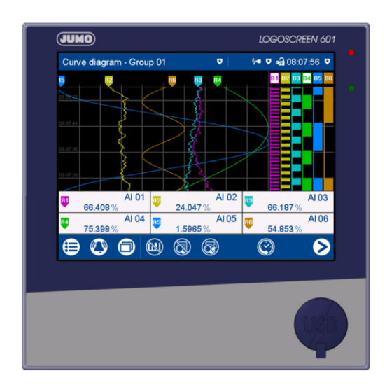
2 Description Display and control elements (1) Touchscreen (TFT color screen) Technical data: chapter 11.1.7 "Screen", Page 271 The screen appearance is described in the "Operation" chapter: chapter 5.1.1 "Touchscreen", Page 37 (2) Alarm LED The LED is lit while an alarm is present. (3) Power LED The LED flashes after switching on the device until the startup process is completed. -
Page 19: Mounting
Mounting 3 Mounting General information on mounting WARNING! The device is not designed for use in potentially explosive areas. Explosion hazard. Only deploy the device outside of potentially explosive areas. Mounting site The device is designed for installation in a panel cut-out. The front of the device and housing have dif- ferent protection types (see technical data). -
Page 20: Dimensions
3 Mounting Dimensions Device 120.9 Panel cut-out Close mounting Distance between panel cut-outs Horizontal Vertical Minimum clearance 20 mm 20 mm Recommended distance (easier mounting of mounting elements) 50 mm 50 mm Device with terminal cover (accessories) 128.1 147.6... -
Page 21: Panel Mounting
3 Mounting Panel mounting Step Action Insert the device into the panel cut-out from the front until the seal is flush with the panel. Insert the mounting elements into the recesses of the housing (one element on each cor- ner, see figure) and use a screwdriver to evenly clamp them against the rear side of the panel with a torque of 1.0 Nm. -
Page 22: Terminal Cover (Accessories)
3 Mounting CAUTION! Sharp or hard objects are not suitable for operating the screen. They can cause scratches and damage the front foil. Only operate the screen with your finger or with a suitable stylus. Terminal cover (accessories) Step Action Screw the spacer bolt (A) into the rear wall of the device. -
Page 23: Universal Carrying Case, Compact (Extra Code 970)
3 Mounting Universal carrying case, compact (extra code 970) Dimensions Intended use The paperless recorder in the carrying case is intended only for use by personnel with technical qualifi- cations who have been specially trained, and have the relevant knowledge in the field of automation technology. - Page 24 3 Mounting chapter 11.1.10 "Case", Page 272...
-
Page 25: Electrical Connection
Electrical connection 4 Electrical connection Installation notes Requirements for personnel • Work on the device must only be carried out to the extent described and, like the electrical connec- tion, only by qualified personnel. • Before plugging and unplugging connecting cables, it must be ensured that the acting person is elec- trostatically discharged (by touching grounded metallic parts, for example). -
Page 26: Galvanic Isolation
4 Electrical connection Galvanic isolation Analog input 1 Analog ouput 1 Analog input 3 Analog ouput 3510 V Relay 1 Analog input Analog input Digital inputs Digital inputs/ 1 to 6 outputs 1 to 12 Digital inputs 7 to 12 USB host- USB device- interface... -
Page 27: Connection Elements
4 Electrical connection Connection elements Front USB host interface (without cover) Back connection elements Slot 3 (option 3) Slot 2 (option 2) Slot 1 (option 1) Connection element and assignment Connection element and assignment USB device interface Relay 1 (changeover contact) Ethernet interface (as a standard feature) or Voltage supply 6. - Page 28 4 Electrical connection NOTE! The front-side USB host interface is intended only for connecting a USB flash drive. Any other use is not admissible. NOTE! The quality of the USB cable and the USB flash drive affects whether or not the device functions correct- ly.
-
Page 29: Connection Diagram
4 Electrical connection Connection diagram 4.4.1 Analog inputs Measuring probe Terminals and connection symbol Connection element.terminal / assignment Thermocouple Analog/digital option (order code 1): 7.1-5 / Analog input 1 8.1-5 / Analog input 2 9.1-5 / Analog input 3 RTD temperature probe 11.1-5 / Analog input 4 Two-wire circuit 12.1-5 / Analog input 5... - Page 30 4 Electrical connection Measuring probe Terminals and connection symbol Connection element.terminal / assignment Resistance/potentiometer Three-wire circuit Resistance/potentiometer Four-wire circuit Voltage DC -10(0) to +10 V Voltage DC -1(0) to +1 V Voltage DC 0 to 70 mV Current DC 0(4) to 20 mA...
-
Page 31: Digital Inputs
4 Electrical connection 4.4.2 Digital inputs Version Terminals and connection symbol Connection element.terminal / assignment Digital input DC 0/24 V, Analog/digital option 1 2 3 4 5 6 7 8 9 10 auxiliary voltage supply DC 24 V (order code 1):: 6.1 / Digital input 1 6.2 / Digital input 2 Example: potential-free contact on... -
Page 32: Analog Outputs
4 Electrical connection 4.4.3 Analog outputs Version Terminals and connection symbol Connection element.terminal / assignment Analog output Analog/digital option 1 2 3 4 5 6 7 8 DC 0 to 10 V or (order code 1): DC 0(4) to 20 mA 6.9 / Analog output 1 + (configurable) 6.10 / Analog output 1 -... -
Page 33: Digital Inputs/Outputs
4 Electrical connection 4.4.4 Digital inputs/outputs Version Terminals and connection symbol Connection element.terminal / assignment Digital input DC 0/24 V Digital option 1 2 3 4 5 6 7 8 (order code 4): digital output DC 0/24 V 14.1 / Digital input/output 1 (individually switchable), 14.2 / Digital input/output 2 Example: potential-free contact on... -
Page 34: Relays
4 Electrical connection 4.4.5 Relays Version Terminals and connection symbol Connection element.terminal / assignment Relay (changeover contact) Relay 1: (max. 3 A at AC 230 V, resistive load) 4.1 / Normally open contact (NO) 4.2 / Common contact (C) 4.3 / Normally closed contact (NC) -
Page 35: Rs232/Rs485 Interface
4 Electrical connection 4.4.6 RS232/RS485 interface Version Connection element.pin / assign- Connection element ment RS232 3.2 / RxD (received data) 9-pin SUB-D socket 3.3 / TxD (transmission data) (switchable to RS485) 3.5 / GND (ground) RS485 3.3 / TxD+/RxD+ (transmission/re- 9-pin SUB-D socket ceived data +) (switchable to RS232) - Page 36 4 Electrical connection...
-
Page 37: Operation
Operation 5 Operation Operating concept The device is equipped with a resistive touchscreen; the operation is menu-driven. User management protects the device against unauthorized access. The different users can be assigned different privileges so that they can only access specific functions. In addition to the visualizations available per default, the setup program can be used to create individual process screens for presenting process data. - Page 38 5 Operation Position Meaning Symbol Left Data transfer via PCC software - Transfer active - Transfer not active No icon Center Batch recording - Recording active - Recording not active (or batch not configured) No icon Right Operating mode - Standard operation - Event operation - Time operation The area on the right shows the logon status as an icon and the time.
-
Page 39: Led Displays
5 Operation The area on the right contains buttons (icons) for screen navigation: The "Home" button takes the user directly to a specific screen (configurable). Pressing the "Next" button (right arrow) selects the next screen on a specific level (e.g., toggle to the next active group). -
Page 40: Main Menu
5 Operation Main menu The main menu contains functions for configuring, parameterizing, and operating the device. View Menu items Scroll up Quit main menu Scroll box (current position within the menu); movable Scroll down 5.2.1 Logon This is the menu in which users log on and off, and change their passwords. The following IDs, names, and passwords are set by default: Users Name... -
Page 41: Configuration
5 Operation chapter 5.8 "Electronic signature", Page 69 5.2.2 Configuration This menu contains functions for configuring the device. The functions are available both on the device and in the setup program (see the "Configuration" chapter in the operating manual). In addition to this, there are functions that can only be configured with the setup program (see the oper- ating manual, chapter "Configuration - only in setup program"... -
Page 42: Service
5 Operation 5.2.6 Service This menu contains various service functions. Default configuration You can store the current device configuration with this function. Similarly, a previously stored configuration can be loaded as the current configuration. 5.2.7 Calibrating the touchscreen This menu enables you to calibrate the touchscreen (position calibration). To do so, you need to tap the center of the crosshairs shown in the corners of the screen one after another. -
Page 43: Alarm List
5 Operation 5.3.1 Alarm list The alarm list shows all alarms that are present in their order of occurrence. If an alarm is no longer pres- ent, its entry is automatically removed from the alarm list. The alarm list is rebuilt after power on. Each alarm represents an event. -
Page 44: Event List
5 Operation 5.3.2 Event list The event list contains event entries in chronological order. A maximum of 150 entries are stored and displayed. When new entries are added, the oldest entries are deleted. The event list is kept after power off. - Page 45 5 Operation Event list in memory view If the alarm and event menu is called up from the memory view (history) (or from the curve presentation of a completed batch), the event list is opened directly. An additional button is available here which lets you mark the time of a specific event in the memory view with the cursor position.
-
Page 46: Visualization Menu (Display)
5 Operation Visualization menu (display) In the visualization menu, the display type and group that should currently be displayed on the device are selected. Up to 6 analog channels and 6 digital channels of a group can be shown on one screen. View Menu items Scroll up... -
Page 47: Curve Diagram
5 Operation 5.4.1 Curve diagram In the curve diagram, the analog and digital signals configured for the relevant group are displayed as analog curves or digital traces. Digital traces and channel information can be hidden in the group con- figuration. The diagram type (horizontal, vertical) is selected individually for each group in the configuration. - Page 48 5 Operation Memory view (history) Move time for memory values forward Time of memory values (cursor position) (later memory values) Cursor (time of numeric memory values) Zoom factor Move time for memory values back (ear- Navigation bar lier memory values) Analog value at selected time Navigation bar Quit memory view...
- Page 49 5 Operation Horizontal diagram In the horizontal diagram, the analog curves and digital traces run from right to left. The channel infor- mation is shown on the right edge of the screen; the icons for event and alarm at the top edge of the screen.
-
Page 50: Digital Diagram
5 Operation 5.4.2 Digital diagram In the digital diagram, the digital signals configured for the relevant group are displayed as digital traces. The diagram type (horizontal, vertical) is selected individually for each group in the configuration. The following view shows the vertical diagram. Accordingly, the description also applies to the horizontal di- agram. -
Page 51: Bar Graph
5 Operation 5.4.3 Bar graph In the bar graph view, the analog signals configured for the relevant group are shown as bar graphs, and the digital signals – depending on their logical state – as colored areas or frames. The diagram type selected for the group (horizontal, vertical) is irrelevant for the bar graph view. The view is always as a column diagram (vertical) and not as a bar diagram (horizontal). -
Page 52: Text Image
5 Operation 5.4.4 Text image The text image shows the current values for the analog signals configured for the relevant group as num- bers. The digital signals – depending on their logical state – are shown as colored areas or frames. Group view Designation (pointer) and signal abbrevi- Digital signal with signal abbreviation... - Page 53 5 Operation Individual view Designation (pointer), signal abbrevia- Bar graph (column diagram) of the ana- tion (configurable), and signal designa- log signal tion (configurable) of the analog signal Current value of analog signal Digital signal with signal abbreviation (configurable) and designation (pointer) Back to group view Displays the logical state: Colored area = HIGH (B1, B3)
- Page 54 5 Operation Individual view with alarms Last alarm to have occurred (here: from Limit value for max. alarm (configurable) analog input 03) Current value of analog signal with color Bar graph (column diagram) of analog change (alarm) signal with color change (alarm) Alarm text of analog input Limit value for min.
-
Page 55: Report
5 Operation 5.4.5 Report A report shows the statistical information for the relevant group. A report contains the maximum, mini- mum, and average values of the analog signals during the recording time (the recording period is con- figurable). A distinction is made between the current (ongoing) report and the completed report. To create a report, it must be activated in the configuration for the relevant group. - Page 56 5 Operation Detailed view Designation (pointer) and signal abbrevi- Completed report ation (configurable) of analog signal; re- port type (configurable; here: external) Time at which the max. value (or min. Current (ongoing) report value) occurred Time stamp for current report: beginning Back to previous view of recording and current time Time stamp for completed report: begin-...
-
Page 57: Current Batch
5 Operation 5.4.6 Current batch This function opens the report for the current batch recording. Batch recording can be started and stopped (depending on the configuration). The report layout is defined in the batch configuration. This is where the individual lines of the report are defined, and the text for the left column, and content of the right column, are specified (device: main menu >... -
Page 58: Completed Batch
5 Operation 5.4.7 Completed batch This function displays the report for the completed batch recording. Recorded data can be shown as a report and as a curve diagram. If necessary, the report can also display the data from current batch recording. View Open report (statistical information for Open curve presentation (analog curves... - Page 59 5 Operation Report for batch Designation (pointer) and signal abbrevi- Data (statistical information) for the com- ation (configurable) of the analog signal pleted batch recording Go to the next analog signal within the Data (statistical information) for the cur- group rent (ongoing) batch recording Back to the batch report view Go to next group...
-
Page 60: Process Screen
5 Operation 5.4.8 Process screen This visualization shows the individual process screens. You can use the arrow keys in the navigation bar to change to the next process screen. Process screens can be created with the setup program and transferred to the device. For a process screen to be displayed, it must be activated (configuration parameters in the setup program;... -
Page 61: Comment Text
5 Operation Detailed view Designation (configurable) of the count- Limit value for max. alarm (configurable) er/integrator Specifications on current counter/inte- Bar graph view of the current counter/in- grator tegrator The type (configurable; here: external) Start and end of the display range are decides when the status is stored and configurable. -
Page 62: Text Input Dialog
5 Operation In the case of a device that has extra code 888 (FDA), the setting in question is performed using the PCS software. The approach when entering a comment with authentication basically corresponds to the one when ren- dering an electronic signature for a completed batch (only steps 2 to 4). Example of an electronic signature: chapter 5.8 "Electronic signature", Page 69 Text input dialog... - Page 63 5 Operation Text input dialog Parameter (designation of the configura- Input box with current text tion parameter from the previous dialog) After changing to the text input dialog, the current text is fully selected. Tapping on the input box displays a cursor. Tap- ping and dragging the cursor lets you se- lect multiple characters.
- Page 64 5 Operation Keyboard mappings Each of the 30 keys in the default keyboard layout can be mapped with up to 10 characters. The Shift key toggles between the first two characters. To select more characters, you need to hold down the rel- evant key for longer.
-
Page 65: Flash Manager
5 Operation Flash manager The Flash Manager menu automatically opens when the device is in basic status and a USB flash drive (FAT16/FAT32 file system) is plugged into the front USB port. If the device is in a menu (main menu, alarm and event list, display), the Flash Manager is opened only after exiting the menu. - Page 66 5 Operation choose any starting time in the past. Using the additional parameter "Save counters/reports" it is pos- sible to save the current readings of the counters and integrators as well as the statistics (report) – even if they have not yet been completed – along with the recording data. •...
- Page 67 5 Operation Saving the recording data of a certain time period In the following example the recording data of a week should be saved. Select time period Determined starting time (editable) The starting time is automatically determined by the device depending on the current date (here: August 04, 2016), the current time (here: 15:00:00), and the selected time period.
-
Page 68: Web Server
5 Operation Web server The device includes a built-in web server which supports online visualization with the help of a web browser. The user can access the process values, various visualizations, and the device's alarm and event list. For access, you need to enter the device's IP address in the address line of the web browser. If needed, you can also use the DNS device name. -
Page 69: Electronic Signature
5 Operation Electronic signature With the extra code 888 (FDA), the user has the option to provide a completed batch or the recording data of a certain time period with their electronic signature. A logged-on user can also provide their sig- nature during logoff –... - Page 70 5 Operation Step Action Select your user ID (in this case: master) The user has to select his/her ID. This step is required because someone other than the cur- rently logged-on user can provide this signature. Enter text that describes the meaning of the signature (evaluation text) using the keyboard. Alternatively, select text from the text list (1) and, if required, edit it: The possibilities of entering a text depend on the configuration (no text available, enter text via keyboard, select text from text list, select text from text list and edit).
- Page 71 5 Operation Step Action Enter password: Confirm process: The process can still be aborted here.
- Page 72 5 Operation Step Action In the report of the completed batch recording, press the button (1) to display the signature that was provided: The signature (here: master) and the meaning of the signature (here: batch o.k.) are dis- played:...
- Page 73 5 Operation Time period The electronic signature for a time period essentially differs from the signature for the completed batch by requiring the time period in question to be selected. The signature applies to the time period that is displayed in the diagram at the time of the signature. The displayed period may have to be expanded prior to signing.
- Page 74 5 Operation...
-
Page 75: Setup Program
Setup program 6 Setup program The setup program is a PC software tool for convenient configuration of the paperless recorder; it offers the following functions: • User-friendly program operation • Support for multiple languages, both in the setup program and in the device (operating language) •... -
Page 76: Logon And Rights
6 Setup program Step Action Enter the license number for the setup program (see CD sleeve; you may also need to enter license numbers for additional functions after installation). If the "30-day test version" option is set during installation, the setup program is fully func- tional for 30 days (full user rights). - Page 77 6 Setup program Right Demo installation Maintenance Specialist Export data to external mass storage (USB flash drive) Import data from external mass storage (USB flash drive) Print Activation of program options Activate extra codes Edit interface settings Edit device settings Delete device Create new device x = Right exists, - = Right does not exist...
-
Page 78: User Interface
6 Setup program User interface Menu bar Toolbar Working area – navigation tree Working area – display window Connection status Online data Menu bar The individual functions of the setup program are launched from the menu bar. chapter 6.3 "Menu bar functions", Page 81... - Page 79 6 Setup program Toolbar The toolbar contains selected functions from the menu bar. These can be launched by left-clicking on them. Hovering the mouse pointer over one of the icons displays the name of the function after a few seconds. Moving the toolbar The user can change the position of the toolbar: Step...
- Page 80 6 Setup program Connection status The "Connection status" line indicates whether a connection to a device exists. In addition, some inter- face data is displayed, e.g., the IP address. The line can be shown and hidden using the Window > Connection status function. Example: No connection Example: Connection to a device The height of the line can be changed by moving the border of the online data window with the aid of the...
-
Page 81: Menu Bar Functions
6 Setup program Menu bar functions This chapter describes the menu bar functions. The order of the subchapters corresponds to the location of the menus in the menu bar (from left to right). Functions that can also be called up via the toolbar are marked with the matching icon here. 6.3.1 File Overview of menu items:... -
Page 82: Edit
6 Setup program Close Removes the settings shown in the working area from the working area and closes the Setup window. The user has the opportunity to save changes that have not yet been saved. Export as RTF text Saves the current setting as an RTF file on the PC. Print ... -
Page 83: Data Transfer
6 Setup program 6.3.3 Data transfer Overview of menu items: Establish Connection ... Opens the device connections list. The device connections list contains all devices to which a connection can be established via the setup program. Devices can be added to or removed from the list. The interface parameters for the connection are also configured in the device connections list. -
Page 84: Extras
6 Setup program 6.3.4 Extras Overview of menu items: Activation of program options Activates optional functions of the setup program (entry of additional license numbers). Using this function, the setup program can also be registered with a valid license number at a later date (30-day test version or full version) if a valid license number was not entered during the installation (demo mode). -
Page 85: View
6 Setup program 6.3.5 View Overview of menu items: Open elements Expands all elements in the working area so that the sub-items and the settings can be viewed. Close elements Collapses all elements in the working area. Full view The working area contains all functions of the setup program. User list The working area contains only the "User list"... -
Page 86: Info
6 Setup program Online data Alternately shows/hides the online data window. A checkmark preceding the menu item indicates that the window is shown. Connection status Alternately shows/hides the line for displaying the connection status. A checkmark preceding the menu item indicates that the line is shown. Opened window (here: Setup 1) Displays the names of all opened setup files as a list. -
Page 87: Setup File
6 Setup program Setup file The setup file contains full details of the device's hardware and software, as well as its configuration. The function File > New or File > Open creates a new setup file, or opens an existing file. 6.4.1 Views and functions Navigation tree... - Page 88 6 Setup program Navigation tree Clicking on the ("-") icon zooms out of the view; clicking on the ("+") icon zooms back in. Double clicking an entry (e.g., "Analog inputs") starts the change dialog. Alternatively, you can initiate changes via the menu bar (Edit > Configuration level > Analog inputs). Display window Double clicking an entry in the display window starts the change dialog.
-
Page 89: Create File Info
6 Setup program Print The function enables the current settings to be printed. You can choose which parameter groups to print and which not to print. Alternatively, printing is also possible via the File menu. 6.4.2 Create file info The file info consists of the file info header and the file info text; and is used to describe the setup file. The information is only stored in the setup file and not transferred to the device. -
Page 90: Transfer Setup File
6 Setup program Only setup chapter 9 "Configuration – in setup program only", Page 199 Online parameters chapter 10 "Online parameter (setup only)", Page 253 6.4.4 Transfer setup file To transfer the setup file, you first need to open a connection between the setup program (PC) and the device. -
Page 91: Configuration
Configuration 7 Configuration This chapter describes the paperless recorder configuration based on the menu items and parameters of the device: Main menu > Configuration The description also applies for the configuration with the setup program. NOTE! The configuration on the device is only available if a user is logged on, and the user has the required rights. - Page 92 7 Configuration Overview of inputs and outputs and internal functions The following table provides an overview of all inputs and outputs, as well as the internal functions with digital or analog output signals. The number of optional inputs and outputs depends on the device ver- sion (see order details, options 1 to 3).
-
Page 93: Selectors
7 Configuration Selectors The selectors contain signals that are available for configuration on the device or in the setup program. These are device signals (e.g., analog and digital inputs or internal signals), and signals that are trans- ferred to the device via an interface (external analog and digital inputs; can also be written using bar- codes). -
Page 94: Digital Selector
7 Configuration 7.1.2 Digital selector Category Signal Description No selection No signal selected Digital inputs Digital input 1 to 12 Signal of digital input Digital inputs/ Digital input/output 1 to 12 Signal of digital input outputs External digital in- Ext. digital input 1 to 24 Signal of external digital input (via interface) puts Math results (digi-... - Page 95 7 Configuration Category Signal Description System alarms Collective alarm Collective alarm of device The signal is active if the alarm list contains at least one entry (an entry is removed as soon as the alarm disappears). Collective alarm with acknowledg- Collective alarm of device;...
-
Page 96: Basic Device (Setup Only)
7 Configuration Basic device (setup only) This menu item is used to change device hardware (optional plug-in boards) and optional functions (ex- tra code, e.g., math/logic) in the current setup project. The following options are available for this pur- pose: •... -
Page 97: Device
7 Configuration Device The general device data is configured in this menu. Device dialog box Parameter Parameter Selection/settings Description Device name Name (example) The device name is used in the setup program, Web server, and the PCC and (max. 20 characters) PCA3000 PC programs. - Page 98 7 Configuration Parameter Selection/settings Description Temperature unit Unit in which the temperature values are entered and displayed. When the unit is device changed, all the relevant values are converted and the display is adjusted. Deg. Celsius Unit = °C Deg. Fahrenheit Unit = °F Temperature unit Unit of the temperature values transferred via the interface (external analog inputs).
-
Page 99: Display
7 Configuration Display This menu is used to implement the following settings: • Screen settings • Colors of the individual items of information in the visualizations • General settings for the various visualizations 7.4.1 Start image and watermark (setup only) Setup dialog box Parameter Parameter... -
Page 100: Screen
7 Configuration 7.4.2 Screen Device dialog box Parameter Parameter Selection/settings Description Brightness 0 to 100 % Screen brightness Screen switch-off The screen can be switched off (darkened) to save energy. Inactive The switch-off is not active. Time If the screen is not touched for a period from 10 to 32767 seconds, the switch-off is activated and the screen turns dark. -
Page 101: Colors
7 Configuration 7.4.3 Colors Device dialog (excerpt) Parameter Parameter Selection/settings Description Analog channel 1 Color ... Color used to display the corresponding analog channel (graphically, numerically, analog channel 6 and in text form). Digital channel 1 Color ... Color used to display the corresponding digital channel (graphically and in text digital channel 6 form). -
Page 102: General Information
7 Configuration 7.4.4 General Information Device dialog (excerpt) Parameter Parameter Selection/settings Description Image after reset: Last image before Yes, No If "Yes" is selected, the last active image reset before the reset (by rebooting or chang- ing the configuration) is also displayed after the reset. - Page 103 7 Configuration Parameter Selection/settings Description Show bar graph Yes, No "Yes" releases the "Bar graph" visualiza- tion for selection by the user. Show text image Yes, No "Yes" releases the "Text image" visual- ization for selection by the user. Show process Yes, No "Yes"...
-
Page 104: Analog Inputs
7 Configuration Analog inputs The analog inputs (optional extra) are universal analog inputs for connecting various measuring probes. For example, the analog inputs are pooled into groups together with other analog signals via the "Groups" configuration and are available for further use via these groups. Device dialog (excerpt) Parameter Parameter... - Page 105 7 Configuration Parameter Selection/settings Description Voltage 0 to 1 V Voltage signal Voltage -1 to +1 V Voltage signal Voltage 0 to 10 V Voltage signal Voltage -10 to +10 V Voltage signal Current 0 to 20 mA Current signal Default setting for analog input 1 to 3 Current 4 to 20 mA Current signal...
- Page 106 7 Configuration Parameter Selection/settings Description Customer-specific 1 to 4 Customer-specific linearization using grid points (pairs of values) or 4th order polynomial Resistance mea- Measuring range for resistance/potentiometer and for customer-specific lineariza- suring range tion with RTD temperature probe 0 to 4000 Ω 0 to 400 Ω...
- Page 107 7 Configuration Parameter Selection/settings Description 0 Ω to 4000 Ω Resistance Ra or For Resistance transmitter: Resistance Ra between sliding contact (S) and start (A), if the sliding contact is positioned at the start. For Resistance/potentiometer: Offset resistance Ro 0 Ω to 1000 Ω to 4000 Ω Resistance Rs or For Resistance transmitter: Resistance range Rs of sliding contact...
-
Page 108: Limit Value Monitoring
7 Configuration Offset To offset plant-specific deviations, the measured value can be corrected (offset) for each analog input (following linearization). A positive or negative form of the correction value is added to the measured val- ue (entering a negative correction value reduces the measured value). Typical applications include com- pensating for the line resistance of a RTD temperature probe in a two-wire circuit. - Page 109 7 Configuration Device dialog box Parameter Parameter Selection/settings Description Activation/Type Inactive Limit value monitoring is inactive. Min. alarm Alarm signal is active if the value drops below the limit value. Max. alarm Alarm signal is active if the limit value is exceeded.
- Page 110 7 Configuration Activation/type, limit value, switching differential Limit value for min. alarm Alarm signal on Limit value for max. alarm Alarm signal off Switching differential Alarm/Event list All events and their time of occurrence are added to the event list. If the event is an alarm, newly occur- ring alarms and their time of occurrence are additionally added to the alarm list.
-
Page 111: Analog Outputs
7 Configuration Analog outputs The analog outputs (optional extra) can each be configured as current or voltage outputs (current signal, voltage signal) and are freely scalable. Device dialog box Parameter Parameter Selection/settings Description Channel designa- AO ... Name (abbreviation) with max. 5 charac- tion ters that is used in the visualizations. - Page 112 7 Configuration Parameter Selection/settings Description Response in case Value of the output signal after deviation above or below the measuring range (out of a fault of range = o-o-r) The selection options "Defined low value" and "Defined high value" are only avail- able for the output signals 4 to 20 mA and 20 to 4 mA.
- Page 113 7 Configuration Behavior after power on During the initialization phase of the device, the output signal assumes a value of 0 V or 0 mA depending on the configuration of the relevant analog output.
-
Page 114: Digital Inputs
7 Configuration Digital inputs The digital inputs (optional extra) are actuated with an external voltage DC 0/24 V or via a potential-free contact (auxiliary voltage in place). The digital inputs are pooled into groups along with other digital signals in the "Groups" configuration and are then available for further use via these groups. - Page 115 7 Configuration Device dialog box Parameter Parameter Selection/settings Description Activation Inactive Signal monitoring is inactive. Active Signal monitoring is active. Alarm/Event list Inactive (signal only) In the event of an alarm, only the alarm signal is activated. Event The alarm/event text is entered in the event list.
- Page 116 7 Configuration Alarm delay In the event of an alarm (parameter "Alarm active at"), the alarm signal is not activated until the delay time has expired. If the alarm case is left in the meantime, the timer restarts when a new alarm case occurs.
-
Page 117: Digital Inputs/Outputs
7 Configuration Digital inputs/outputs The digital inputs/outputs (optional extra) can be individually switched between input and output. The in- puts are actuated with an external voltage DC 0/24 V or via a potential-free contact (auxiliary voltage in place). The outputs provide an output signal of DC 0/24 V. As digital inputs, they are pooled into groups along with other digital signals in the "Groups"... - Page 118 7 Configuration Device dialog box Parameter Parameter Selection/settings Description Activation Inactive Signal monitoring is inactive. Active Signal monitoring is active. Alarm/Event list Inactive (signal only) In the event of an alarm, only the alarm signal is activated. Event The alarm/event text is entered in the event list.
- Page 119 7 Configuration Alarm delay In the event of an alarm (parameter "Alarm active at"), the alarm signal is not activated until the delay time has expired. If the alarm case is left in the meantime, the timer restarts when a new alarm case occurs.
-
Page 120: Relays
7 Configuration Relays The device is equipped with a relay output (changeover contact). Device dialog Parameter Parameter Selection/settings Description Signal source Digital selector Digital signal for controlling the relay No selection "No selection" means that the relay is in idle state. Channel designa- REL 01 Name (abbreviation) with max. -
Page 121: External Analog Inputs
7 Configuration 7.10 External analog inputs The external analog inputs are analog signals that are transferred to the device via an interface from ex- ternal systems. The external analog inputs can also be written by a barcode scanner (see chapter 11.4.2 "Texts and process values", Page 276). The external analog inputs are pooled into groups along with other analog signals via the "Groups"... -
Page 122: Limit Value Monitoring
7 Configuration Parameter Selection/settings Description Decimal places Number of pre-decimal and decimal places for the numerical display of the input value Even if the number of decimal places is fixed, the format is automatically changed if needed in order to display all digits before the decimal point. Auto Automatic XXXXXp... - Page 123 7 Configuration Device dialog box Parameter Parameter Selection/settings Description Activation/Type Inactive Limit value monitoring is inactive. Min. alarm Alarm signal is active if the value drops below the limit value. Max. alarm Alarm signal is active if the limit value is exceeded.
- Page 124 7 Configuration Activation/type, limit value, switching differential Limit value for min. alarm Alarm signal on Limit value for max. alarm Alarm signal off Switching differential Alarm/Event list All events and their time of occurrence are added to the event list. If the event is an alarm, newly occur- ring alarms and their time of occurrence are additionally added to the alarm list.
-
Page 125: External Digital Inputs
7 Configuration 7.11 External digital inputs The external digital inputs are digital signals that are transferred to the device via an interface from ex- ternal systems. The external digital inputs can also be written by a barcode scanner (see chapter 11.4.2 "Texts and process values", Page 276). The external digital inputs are pooled into groups along with other digital signals in the "Groups"... -
Page 126: Signal Monitoring
7 Configuration 7.11.1 Signal monitoring Signal monitoring (alarm) can be activated for each external digital input. Device dialog box Parameter Parameter Selection/settings Description Activation Inactive Signal monitoring is inactive. Active Signal monitoring is active. Alarm/Event list Inactive (signal only) In the event of an alarm, only the alarm signal is activated. - Page 127 7 Configuration Alarm delay In the event of an alarm (parameter "Alarm active at"), the alarm signal is not activated until the delay time has expired. If the alarm case is left in the meantime, the timer restarts when a new alarm case occurs.
-
Page 128: External Text Variables
7 Configuration 7.12 External text variables The device can receive external texts (text variables) via an interface; the texts are used for batch re- porting. The external text variables can also be written by a barcode scanner (see chapter 11.4.2 "Texts and process values", Page 276). -
Page 129: Limit Value Monitoring Functions
7 Configuration 7.13 Limit value monitoring functions The general limit value monitoring functions can be used for different analog signals. Each limit value monitoring function delivers a status signal and an alarm signal: • The status signal is active (1), if a max. alarm or a min. alarm was enabled and the limit value is ex- ceeded or the value drops below the minimum (limit value infringement). -
Page 130: Alarm
7 Configuration Parameter Selection/settings Description Response in case Behavior of the status signal if the input signal delivers an error value. of a fault Signal inactive Status signal is inactive. Signal active Status signal is active. Signal unchanged Status signal keeps the state it had be- fore the fault. - Page 131 7 Configuration Parameter Selection/settings Description Switching differ- 0 to 99999 The switching differential is used to sup- ential press constant switching of the status signal in the event of fluctuations of the input signal around the limit value. Alarm suppres- Digital selector The selected digital signal (high-active) sion...
-
Page 132: Counters/Integrators
7 Configuration 7.14 Counters/integrators The counters/integrators can be configured as counters, integrators, operating time counters, high- speed counters, or for determining the total flow (volume): • Counters are used to count digital signals. • Integrators are used to integrate analog inputs. •... - Page 133 7 Configuration Parameter Selection/settings Description Day of the week Sunday, Monday, Tuesday, Wednesday, Day of the week on which the counters Thursday, Friday, Saturday and integrators for which the "Type" pa- rameter is configured as "Weekly", are saved at the synchronization time and restarted with the start value 0.
-
Page 134: Specific Settings
7 Configuration 7.14.2 Specific settings Device dialog (excerpt) – counter/integrator 1 ... Parameter Parameter Selection/settings Description Function Operating mode of the counter/integrator Inactive Counter/integrator is switched off. Counter Counter for the pulses of a digital signal Integrator Integration of an analog signal Flow ... - Page 135 7 Configuration Parameter Selection/settings Description Type This setting decides when the current status of the counter/integrator is saved. De- pending on the specific setting (Yes - No), the parameters from the previous chapter "General settings" must also be taken into consideration. Periodically Completion and restart will be deter- mined by the "Period"...
- Page 136 7 Configuration Parameter Selection/settings Description Additional The parameter decides whether the current statuses are to be saved additionally storage (in addition to the save operation resulting from the "Type" parameter). The current statuses are saved but not reset. Depending on the specific setting (Yes - No), the parameters from the previous chapter "General settings"...
- Page 137 7 Configuration Parameter Selection/settings Description Time base "Integrator" function: The current measured value is integrated corresponding to the selected time base, taking the factor into consideration: Second The measured value is divided by 1 and added up every second. Minute The measured value is divided by 60 and added up every second.
- Page 138 7 Configuration Device dialog – counter/integrator 1 ... – display Parameter Parameter Selection/settings Description Channel designa- C/I ... Name (abbreviation) with max. 5 charac- tion ters that is used in the visualizations. Use default text or enter other text. Channel descrip- Counter/integrator ...
- Page 139 7 Configuration Parameter Selection/settings Description Decimal places Pre-decimal and decimal places for the numerical display of the counter or integra- tor status Even if the number of decimal places is fixed, the format is automatically changed if needed in order to display all digits before the decimal point. Auto Automatic XXXXXp...
- Page 140 7 Configuration Device dialog – counter/integrator 1 ... – limit value monitoring function (alarm 1, alarm 2) Limit value monitoring with one or two limit values (alarm 1, alarm 2) can be activated for each counter/ integrator. In out-of-limit cases, an alarm signal is activated. Depending on the configuration, an entry is made in the event list or additionally in the alarm list.
- Page 141 7 Configuration Parameter Selection/settings Description Alarm suppres- No selection The selected digital signal (high-active) sion prevents the alarm signal being activat- Digital selector Alarm delay 0 s to 32767 s Delay time for alarm signal activation...
-
Page 142: Flow
7 Configuration 7.15 Flow Two methods are available for flow measurement (volume flow, volume per unit of time): computation based on a digital signal (signal type "Digital", e.g., rotary pulses of a paddlewheel) and the evaluation of an analog signal (signal type "Analog signal"). NOTE! For the "Digital"... - Page 143 7 Configuration Parameter Selection/settings Description Unit Conversion factor for evaluating the measured value (only for the signal type "Ana- log signal") The units stated in brackets are used in the device info. Unit (conversion factor): l/s (l/s) Liters per second (1) l/min (l/m) Liters per minute (60) l/h (l/h)
-
Page 144: Limit Value Monitoring
7 Configuration Parameter Selection/settings Description Low flow sup- -99999 to 0 to +99999 Limit value for suppressing low flow val- pression ues (any prefix sign) A flow value that is below this limit value is no longer acquired. Signal type, unit In addition to standardization at the analog input, for the "Analog signal"... - Page 145 7 Configuration Parameter Parameter Selection/settings Description Activation/Type Inactive Limit value monitoring is inactive. Min. alarm Alarm signal is active if the value drops below the limit value. Max. alarm Alarm signal is active if the limit value is exceeded. Alarm/Event list Inactive (signal only) In out-of-limit cases, only the alarm sig- nal is activated.
- Page 146 7 Configuration Alarm suppression, alarm delay Alarm suppression and alarm delay prevent or delay entries being added to the event list and alarm list, activation of the collective alarm, the display in the status bar, and the color change (analog value, plotter trace).
-
Page 147: Math
7 Configuration 7.16 Math The optional math function (extra code 260 "Math/Logic") supports formulas which can be freely used for mathematical calculations (analog values). In addition, functions for calculating the differential, ratio, and relative humidity are also provided. In this case, two analog values (variables a and b), for example, the measured values of analog input 1 and 2 are linked to each other. - Page 148 7 Configuration Parameter Parameter Selection/settings Description Function Without function Function is switched off. Formula Mathematical links with freely selectable variables and operators Differential (a-b) Differential of variable a and variable b Ratio (a/b) Ratio of variable a to variable b Humidity (a;b) Calculation of relative humidity Variable a: Dry-bulb temperature...
- Page 149 7 Configuration Parameter Selection/settings Description Variable a Analog selector Analog signal a (for calculating the differ- ential, ratio, and humidity, and determin- ing the floating average) Variable b Analog selector Analog signal b (for calculating the differ- ential, ratio, and humidity) Save using power Only if function = formula: If "Yes", the current value is saved upon switch-off...
-
Page 150: Limit Value Monitoring
7 Configuration Formula as text, Formula Editor Pressing the "Formula Editor" button opens an editor that can be used to create formulas by selecting variables and operators (max. 600 ASCII characters). Formulas can be entered freely in line with stan- dard mathematical rules. - Page 151 7 Configuration Device dialog box Parameter Parameter Selection/settings Description Activation/Type Inactive Limit value monitoring is inactive. Min. alarm Alarm signal is active if the value drops below the limit value. Max. alarm Alarm signal is active if the limit value is exceeded.
- Page 152 7 Configuration Activation/type, limit value, switching differential Limit value for min. alarm Alarm signal on Limit value for max. alarm Alarm signal off Switching differential Alarm/Event list All events and their time of occurrence are added to the event list. If the event is an alarm, newly occur- ring alarms and their time of occurrence are additionally added to the alarm list.
-
Page 153: Logic
7 Configuration 7.17 Logic The optional logic function (extra code 260 "Math/Logic") supports formulas which can be freely used for logical operations (binary values). The results are available in the digital selector. If the function is not active, the logical value = 0. Activating the function On the device, the Logic function is only available when activated. -
Page 154: Signal Monitoring
7 Configuration Setup dialog box Parameter Parameter Selection/settings Description Formula as text View of the formula created with the For- mula Editor (max. 600 ASCII characters) The formula can also be edited in this field. All other parameters and their settings are identical to the configuration on the device. Formula as text, Formula Editor Pressing the "Formula Editor"... - Page 155 7 Configuration In alarm cases, an alarm signal is activated. Depending on the configuration, an entry is made in the event list or additionally in the alarm list. In the latter case, the alarm/event text is displayed in the status bar (until another alarm occurs);...
- Page 156 7 Configuration Alarm/Event list All events and their time of occurrence are added to the event list. If the event is an alarm, newly occur- ring alarms and their time of occurrence are additionally added to the alarm list. If an alarm is made in- active, it is removed from the alarm list and the time of removal is added to the event list.
-
Page 157: Groups
7 Configuration 7.18 Groups The user can configure up to four groups each with a maximum of six analog channels and six digital channels. During the configuration, the user specifies whether the channels in a group can only be viewed, or also stored, and how data recording occurs (memory cycle, storage method). Grouping channels offers the ability, for example, •... -
Page 158: Analog Channels
7 Configuration 7.18.2 Analog channels A group can consist of up to six analog channels (Channel 1 to Channel 6). Device dialog box Parameter Parameter Selection/settings Description Input signal Analog selector Signal source for the channel No selection Default setting for group 1: Channel 1: analog input 1 Channel 2: analog input 2 Channel 3: analog input 3... - Page 159 7 Configuration Parameter Selection/settings Description Upper switching Only available for channel 1 of a group. differential -100 to -2 to 0 If there is a positive tolerance violation, the current measured value from chan- nel 2 to 6 must first drop below the cur- rent measured value of channel 1, plus the upper tolerance band limit and upper switching differential, in order for the...
- Page 160 7 Configuration Example of tolerance band monitoring The principle of the alarm follows the alarm configuration of the individual analog channels. Lower alarm Alarm on Upper alarm Alarm off Switching differential Channel 1: Measured value = 21°C (reference value) Upper tolerance band limit = 10°C Upper switching differential = -2°C Channel 2: Tolerance band is active.
-
Page 161: Digital Channels
7 Configuration 7.18.3 Digital channels A group can consist of up to six digital channels (Channel 1 to Channel 6). Device dialog box Parameter Parameter Selection/settings Description Input signal Digital selector Signal source for the channel No selection 7.18.4 Diagram view Device dialog box... - Page 162 7 Configuration Parameter Parameter Selection/settings Description Display channel This parameter is used to switch on and switch off the channel information display information in the curve diagram: channel designation (e.g., A1) along with the abbreviation of the analog or digital signal (e.g., AI01 for analog input 1) and numerical display of the analog value.
-
Page 163: Standard Operation
7 Configuration 7.18.5 Standard operation When standard operation is activated, the measurement data is recorded at the configured memory cy- cle unless one of the following operating modes is active: • Event operation • Time operation Standard operation has the lowest priority compared with time and event operation. Device dialog box Parameter Parameter... - Page 164 7 Configuration Parameter Selection/settings Description Memory cycle 0 s ... 5 s ... 32000 s The memory cycle is configured here. Depending on the configuration of the "Memory values" parameter, the mea- surement data is saved when the config- ured time has elapsed. The smaller the memory cycle, the more data needs to be saved.
-
Page 165: Event Operation
7 Configuration 7.18.6 Event operation Event operation is enabled by a control signal; it can be used, for example, to shorten a memory cycle during an alarm. Event operation has the highest priority of all three operating modes. Device dialog box Parameter Parameter Selection/settings... -
Page 166: Time Operation
7 Configuration 7.18.7 Time operation A time frame is defined for time operation (max. 24 hours); during this period, a specific memory value and a specific memory cycle are active. Time operation has higher priority compared with standard operation, but lower priority than event oper- ation. -
Page 167: Counters/Integrators
7 Configuration 7.18.8 Counters/integrators Up to 6 counters/integrators can be assigned to each group. Alarms of these counters/integrators then cause an entry to be made in the event list and alarm list of the batch concerned (depending on the con- figuration). -
Page 168: Event Texts
7 Configuration 7.18.9 Event texts Each group can be assigned additional event texts selected from the text list. The selection is controlled by up to 5 digital signals or one analog signal which determine the text number in the text list. Each time the text number is changed, the corresponding text is copied from the text list into the event list. -
Page 169: Alarm Signals
7 Configuration Digital signal Digital signal Digital signal Digital signal Digital signal Decimal value 5 (bit 4) 4 (bit 3) 3 (bit 2) 2 (bit 1) 1 (bit 0) 0 = "No selection" in the digital selector or signal is inactive. 1 = Signal selected and signal is active (high active). -
Page 170: Report
7 Configuration 7.19 Report A report can be generated for each of the groups. The maximum value, the minimum value, and the av- erage value of each analog channel referring to the selected reporting period are saved in a report. NOTE! Processing any changes to the configuration: All reports are completed, saved, and restarted. - Page 171 7 Configuration Parameter Selection/settings Description Annual Specifies whether a report runs for a whole year. Completion and restart occur at 00:00 on the first day of the year Off, On If "On", the yearly report will be run. Total Total specifies whether a report is to be run for the total duration of the current con- figuration of the device.
- Page 172 7 Configuration etc. NOTE! The principle is the same for all reports relating to the synchronization time (daily, weekly, and periodical report). For a daily report, the first report will usually not run for 24 hours and the first weekly report will usually not run for 7 days.
-
Page 173: Batches
7 Configuration 7.20 Batches The device supports reporting of one batch. The batch data is recorded along with the channels for the groups and displayed in batch visualizations. NOTE! To use batch reporting at least one group must be active. 7.20.1 General Information Device dialog box... - Page 174 7 Configuration Parameter Selection/settings Description Recipe header Recipe For a completed batch, the recipe head- er is displayed as a title above a com- Use default text or enter other text. ment text (e.g., Recipe). Text selection bit Digital selector Bit 0 (LSB) to bit 5 (MSB) form a binary number which defines a text from the text No selection...
-
Page 175: Batch Lines
7 Configuration 7.20.2 Batch lines Device dialog box Parameter Parameter Selection/settings Description Text left column Program name (in line 1) This parameter specifies the text in the left column for the selected line of the Use default text or enter other text. batch report. - Page 176 7 Configuration Parameter Selection/settings Description Batch end End (date and time) of batch reporting Batch duration Time difference between batch start and batch end Barcode The text in the selected line will be filled by a barcode scanner. User name Name of logged-on user External text variable ...
- Page 177 7 Configuration Parameter Selection/settings Description Editable This parameter enables editing of the text within the current batch report. Yes, No If "No," the text in the right column can only be edited by modifying the "Default text". If "Yes", the text in the right column – for the current batch report –...
-
Page 178: Ethernet
7 Configuration 7.21 Ethernet The device may be integrated into a company network via the Ethernet interface. The following functions are available via Ethernet: • Communication with PC software such as the setup program, PCC, PCA3000 • Web server for using a web browser •... - Page 179 7 Configuration Parameter Selection/settings Description DNS device MAC000cd8094ecd-TYP7065... Example of a unique DNS device name name (assigned by default) Admissible characters: a ... z, A ... z, -, 0 ... 9 (max. 63 charac- If necessary, the name can also be as- ters);...
- Page 180 7 Configuration NOTE! If DHCP is active, a DNS device name should always be used so that the device can also be addressed if the IP address is changed. DNS server The DNS server responds to requests from the network to resolve a DNS device name into an IP ad- dress.
-
Page 181: Serial Interface
7 Configuration 7.22 Serial interface The device is equipped with a serial interface which is configurable as an RS232 or RS485 interface. The interface supports the Modbus protocol (Modbus RTU) as a master or slave. Alternatively, a barcode scanner may be connected. For more information on using the serial interface with the Modbus protocol, see: chapter 9.7 "Modbus frames for reading", Page 220 chapter 9.8 "Modbus frames for writing", Page 221... -
Page 182: Modbus Slave
7 Configuration Parameter Selection/settings Description Data format Data format with which the interface is operated. 8 - 1 - no parity 8 data bits, 1 stop bit, no parity 8 - 1 - odd parity 8 data bits, 1 stop bit, odd parity 8 - 1 - even parity 8 data bits, 1 stop bit, even parity Min response... -
Page 183: Modbus Master
7 Configuration Parameter Selection/settings Description Alarm/Event text Use default text or enter other text. Text that is displayed in the event of an alarm and entered in the alarm and event list. Timeout 250 to 2000 to 99999 ms Time period for timeout monitoring. After this time, a failure of the Modbus master is identified. -
Page 184: Modbus-Tcp
7 Configuration 7.23 Modbus-TCP This menu is used to implement settings for the Modbus-TCP operating mode. If the device is a Modbus slave, two external devices (Master 1 and Master 2) can access the device at the same time. If it is a Modbus master, it can communicate with up to four external devices (Device 1 to Device 4). -
Page 185: Modbus Master
7 Configuration Parameter Selection/settings Description Master 1, Master 2 Timeout Monitoring is not active. monitoring Monitoring is active. IP address 0.0.0.0 IP address of the Modbus master for tim- eout monitoring The address must be set. Timeout 250 to 2000 to 99999 ms Time period for timeout monitoring After this time, a failure of the Modbus master is identified. - Page 186 7 Configuration Parameter Selection/settings Description Scanning cycle 60 ... 500 ... 99999 ms The Modbus master requests data from the Modbus slave at these intervals. Device 1 to Device 4 IP address 0.0.0.0 IP address of Modbus slave The address must be set. Port 0 ...
-
Page 187: Time Settings
7 Configuration 7.24 Time settings The settings in this dialog are used to synchronize multiple devices by means of a control signal. NOTE! The date and time are set in the device parameterization or setup program (online parameters). The PC's date and time are used for the settings in the setup program. -
Page 188: Time Server (Sntp)
7 Configuration 7.25 Time server (SNTP) The time and date of the paperless recorder can be synchronized with a time server using the SNTP protocol (Simple Network Time Protocol). Device dialog box Parameter Parameter Selection/settings Description Synchronize with Time/date of device are not synchro- server nized. -
Page 189: Undocumented Parameters
7 Configuration Deviation tolerance Time and date synchronization depends on the deviation tolerance (30 s). If the deviation of the time/date between the server and the device is less than or equal to the deviation tolerance, the time on the device is slowly modified (the internal clock runs slightly faster or slower) with- out needing reconfiguration. - Page 190 7 Configuration...
-
Page 191: Parameterization
Parameterization 8 Parameterization This chapter describes the parameterization of the paperless recorder; this is only possible on the de- vice: Main menu > Parameterization A parameter that is also configurable in the setup program or via an interface will be pointed out. NOTE! The parameterization on the device is only available if a user is logged on, and the user has the required rights. - Page 192 8 Parameterization Target start value: 20 °C (reference measurement) Actual end value: 70 °C (displayed value) Target end value: 80 °C (reference measurement) 15°C / 70°C 20°C / 80°C 20°C / 80°C Display values Reference values Furnace Sensor in RTD temperature probe Performing fine adjustment 1) Determine the lower value (as low and constant as possible) with the reference measuring device.
-
Page 193: Counters/Integrators
8 Parameterization Counters/integrators This function is used to change the current counter/integrator status (e.g., to 0 or any other value). The counter/integrator continues to run with this new value, but the period for adding the total is not restarted. The change is logged in the event list specifying the old and new values and is only effective once. The old value is not stored. -
Page 194: Limit Value Monitoring Functions
8 Parameterization Limit value monitoring functions The limit value and switching differential in the general limit value monitoring functions are also adjust- able in the parameterization. The prerequisite for this is that limit value monitoring has been previously configured. chapter 7.13 "Limit value monitoring functions", Page 129 Limit value and switching differential can be configured in the configuration as well as via an interface. -
Page 195: Date And Time
8 Parameterization Date and time This function is used to set the current date and the current time on the device and to select the time zone. Additionally, settings for the start and end of daylight saving time are configured here. The device date and time can also be set with the setup program using the PC's date and time: chapter 10.2 "Date and time", Page 254 The date and time can also be set using a time server:... - Page 196 8 Parameterization Parameter Selection/settings Description End of January to October to December Month daylight saving First, second, third, fourth, last Day of the week in month time Sunday to Saturday, 1 to 31 Day of the week/day 00:00 to 03:00 to 24:00 Time NOTE! In the setup program, the time zone and daylight saving time are set during the configuration (Configu-...
-
Page 197: Batches
8 Parameterization Batches This function specifies a start number for the batch number of the respective batch. The batch number is used in the batch report. At the end of batch reporting, the value is incremented by one. Device dialog box Parameter Parameter Selection/settings... -
Page 198: System Data
8 Parameterization System data The "Country settings after power on" parameter determines whether the language and other country- specific settings (temperature unit, time zone, daylight saving time) can be selected when the device is next powered on. This parameter can also be set in the configuration, but only with the setup program: chapter 7.3 "Device", Page 97 The "Transmit user separately"... -
Page 199: Configuration - In Setup Program Only
Configuration – in setup program only 9 Configuration – in setup program only NOTE! The functions described in this chapter can only be configured with the setup program. Default settings are shown in bold in the parameter tables. Country settings Text library The text library is used to manage the various language and country-specific settings, such as the date format and decimal point, independently of the project. - Page 200 9 Configuration – in setup program only Parameter Selection/settings Description Date format DDMMYYYY Example: 31.12.2010 MMDDYYYY Example: 12-31-2010 YYYYMMDD Example: 2010-12-31 Separating point Use the default character or enter anoth- Example of separating point ":" (colon): (time) er character. 23:59:59 Separating point Use the default character or enter anoth- Example of separating character "/"...
- Page 201 9 Configuration – in setup program only Selection Submenu Function New language ... From another library The new language is created from anoth- er text library. To do this, the user needs to select the text library from a directory (file with the suffix ".dat").
-
Page 202: User List
9 Configuration – in setup program only User list The user IDs, names, and passwords for various users are assigned in the user list, and the user rights are managed. The system supports up to five users with varying rights. These settings are crucial for logging onto the device. - Page 203 9 Configuration – in setup program only Parameter Selection/settings Description Group 1 ... Select relevant user group from the drop- The following parameters "Group desig- Group 15, down list. nation" and "Rights" refer to the selected Public rights user group. The rights for users that are not logged on are defined by selecting "Public rights".
-
Page 204: Default User Settings
9 Configuration – in setup program only 9.2.1 Default user settings User 1 (Master) is assigned all rights by default. Users 2 to 4 (User 1 to User 3) and User 5 (Service) have limited rights. User 5 is designed for performing service functions. It differs from User 1 in that the user cannot manage any other users or delete recording data. -
Page 205: Character Table
9 Configuration – in setup program only 9.2.3 Character table The character table is used to define the characters available for assigning passwords. The characters are displayed on the device in the form of a virtual keyboard, which is organized in levels. If the setup program is used to assign or change a password, only the characters specified in the setup program are admissible. -
Page 206: Public Rights
9 Configuration – in setup program only 9.2.4 Public rights Public rights apply to users who are not logged on to the system. Setup dialog box Assign rights The rights are listed as a tree structure. A click on "+" expands the view: The relevant sub-items (single rights) become visible. -
Page 207: User Rights
9 Configuration – in setup program only 9.2.5 User rights User rights apply to a user logged onto the device. Setup dialog box Assign rights The rights are listed as a tree structure. A click on "+" expands the view: The relevant sub-items (single rights) become visible. -
Page 208: Overview Of Rights
9 Configuration – in setup program only 9.2.6 Overview of rights The following rights can be assigned as public rights and user rights. Category Individual right Setup Write configuration Time setting Fine adjustment (on the device) Read configuration Recording data Read out recording data, incl. - Page 209 9 Configuration – in setup program only Effects of rights (on the device) Individual right Effect Write configuration The configuration can be written (edited) and read (only writing is possible in the setup program). The affected menu items or functions are available in the individual menus (Main menu: Configuration;...
-
Page 210: Behavior After Power On
9 Configuration – in setup program only Individual right Effect Set counter The menu items "Counters/Integrators" (set initial value) and "Batch" (enter batch number) are available in the main menu, "Parameterization" sub- menu. Alarms acknowledge- The collective alarm can be acknowledged in the alarm list. ment Service The "Service"... -
Page 211: Text List
9 Configuration – in setup program only Text list These texts are available for all functions that allow text to be selected from the text list. In this menu, the texts can be edited individually for each of the device languages. Setup dialog box Parameter Parameter... -
Page 212: Email
9 Configuration – in setup program only Email An email alarm can be sent to up to three address simultaneously via a mail server. Up to 5 alarm texts can be configured; sending is controlled using a digital signal. Setup dialog box Parameter Parameter Selection/settings... -
Page 213: Email Server
9 Configuration – in setup program only NOTE! Email transmission should be tested in the scope of startup. If there is an error, this leads to an entry with an error code in the device's event list. The interface description contains a list of all error codes ("Error codes as integer return values"). 9.4.1 Email server NOTE! - Page 214 9 Configuration – in setup program only Parameter Selection/settings Description SMTP port num- Port number of the email server for SMTP Change the port number if applicable (depending on the email provider and (normally: TLS = 465, StartTLS = 587) type of encryption).
-
Page 215: Web Server
9 Configuration – in setup program only Web server The integrated web server provides the user with convenient access to process values, various visual- izations, and the device's alarm and event list from a web browser. Access can be password protected. The device has a maximum of 2 MB memory for HTML pages. - Page 216 9 Configuration – in setup program only Function of buttons Button Designation Description Import Web Select the folder that contains the files required for the Web application (incl. HTML files). Export Web Select the folder to which the files used for the Web applica- tion should be exported.
- Page 217 9 Configuration – in setup program only Parameter Parameter Selection/settings Description Password active Yes ( ), No ( ) If "Yes," the user needs to log on with their user name and password to be able to access the website. No logon is required for "No".
-
Page 218: Electronic Signature
9 Configuration – in setup program only Electronic signature This menu item is included if extra code 888 (FDA) is available. These settings are significant for the appearance and text entry during an electronic signature. If an elec- tronic signature can even be provided – or whether it must be provided – depends on the configuration in the PC Security Manager software PCS. - Page 219 9 Configuration – in setup program only Parameter Selection/settings Description Display text list Yes ( ), No ( ) By selecting "Yes" the evaluation text (meaning) can be selected from the text list. First text 1 to ... First selectable text (text number) in the text list Number of texts 1 to 50...
-
Page 220: Modbus Frames For Reading
9 Configuration – in setup program only Modbus frames for reading This function is used to compile up to 32 Modbus frames for reading process values from external de- vices (via interface) individually for each opposite end. The process values (analog and digital values; texts) are written to the selected variables (external inputs and texts) from the received Modbus telegram and are available for use in the paperless recorder. -
Page 221: Modbus Frames For Writing
9 Configuration – in setup program only Modbus frames for writing This function can be used to compile up to 32 Modbus frames for writing the paperless recorder's pro- cess values to external devices (via interface) individually for each opposite end. The paperless recorder writes the process values (analog and digital values;... -
Page 222: Profinet
9 Configuration – in setup program only PROFINET The paperless recorder can also be equipped with a PROFINET interface and integrated into a PROF- INET network as an IO device as an optional extra. The interface also supports simultaneous use of Ethernet standard services;... -
Page 223: St Code
9 Configuration – in setup program only 9.10 ST code The user has the option to create his/her own application using the "structured text" option (extra code). The application is created with the ST editor, which is part of the setup program, in the PLC programming language "structured text". - Page 224 9 Configuration – in setup program only Variables bool_out01 to bool_out40 Parameter Selection/text/value Description Description <Enter text> Description of the Boolean output variables Use default text or enter other text. Designation <Enter text> Abbreviation of variables Use default text or enter other text.
- Page 225 9 Configuration – in setup program only Parameter Selection/settings Description Alarm active at High (1) Alarm at high level (1) Low (0) Alarm at low level (0) Alarm/Event text Use default text or enter Text entered in the alarm and event list and dis- other text.
-
Page 226: Customized Linearization
9 Configuration – in setup program only 9.11 Customized linearization You can use the customer-specific linearization to create a customized linearization characteristic line for analog inputs. This characteristic line is used for all analog inputs for which the corresponding linear- ization has been selected in the configuration. - Page 227 9 Configuration – in setup program only Measured value The following table shows the admissible measured value range of the analog inputs as a function of the selected sensor. These values represent the minimum and maximum input values of customer-specific linearization.
-
Page 228: Formula
9 Configuration – in setup program only 9.11.1 Formula Customer-specific linearization is specified using a 4th order polynomial. The polynomial is calculated for the entire linearization range. Polynomial formula: y = X4*x + X3*x + X2*x + X1*x + X0 Setup dialog box Parameter Parameter... -
Page 229: Grid Values
9 Configuration – in setup program only Displaying linearization on a graphic ("Display graphic" button) Use this button to create a graphic of the linearization. The graphic includes the characteristic lines for both types of linearization where applicable, namely the formula and the grid points (table). - Page 230 9 Configuration – in setup program only NOTE! A measured value outside of the definition range results in a deviation above or below the measuring range (out of range). Displaying linearization on a graphic ("Display graphic" button) Use this button to create a graphic of the linearization. The graphic includes the characteristic lines for both types of linearization where applicable, namely the grid points (table) and the formula.
-
Page 231: Process Screens
9 Configuration – in setup program only 9.12 Process screens Process screens are used for visualizing process data. The setup program can be used to create indi- vidual process screens that are transferred to the device and are available there in the "View" menu. The size of a process screen (background) is 640 pixels (width) by 379 pixels (height). -
Page 232: Background
9 Configuration – in setup program only Button Function Copy object to another object (only within the same process screen) Paste cut object into the object list Add new object to the object list Remove object from the object list Move object up in object list Move object down in object list Edit object... - Page 233 9 Configuration – in setup program only Setup dialog box Parameter Parameter Selection/settings Description Image name Selection from list of images Background image for the process screen X position 0 ... 639 X coordinate of the upper left corner of the background image in the process screen Y position...
-
Page 234: Object Types
9 Configuration – in setup program only NOTE! If you import an image with a higher resolution, the process screen editor scales the image to the max- imum admissible size. The aspect of the original image is kept. Similarly the color depth of the image is reduced to 16-bit if the image file you are importing uses more colors. -
Page 235: General Object Features
9 Configuration – in setup program only 9.12.4 General object features The description of the general object features applies for all object types for which the parameters in question are available. The specific object features are described in the following chapters under the corresponding object type. Setup dialog box Parameter Parameter... - Page 236 9 Configuration – in setup program only Parameter Selection/settings Description Foreground color Select color (drop-down menu). Font color within the object Font size Select font size (drop-down menu). Font size within the object Alignment Select alignment (drop-down menu). Alignment of the font within the object (left-aligned, right-aligned, centered) Orientation Select orientation (drop-down menu).
-
Page 237: Pictogram
9 Configuration – in setup program only 9.12.5 Pictogram Setup dialog box Parameter Parameter Selection/settings Description Signal source Digital signal whose status is displayed via the corresponding pictogram. No selection No signal selected. (Pictogram for FALSE (0) will be dis- played.) Select signal. -
Page 238: Analog Signal
9 Configuration – in setup program only 9.12.6 Analog signal Setup dialog box Parameter Parameter Selection/settings Description Signal source Analog signal whose value within the object is displayed numerically. No selection No signal selected. (Display: -----) Select signal. Analog selector Decimal places Select format (drop-down menu). -
Page 239: Digital Signal
9 Configuration – in setup program only 9.12.7 Digital signal Setup dialog box Parameter Parameter Selection/settings Description Signal source Digital signal whose status within the object is displayed via a text. No selection No signal selected. (Text for low condition will be displayed.) Select signal. -
Page 240: Text
9 Configuration – in setup program only 9.12.8 Text Setup dialog box Parameter Parameter Selection/settings Description Text source Text source whose text is displayed within the object. No selection No text source selected. Select signal. The selection must be of the "Text" data type. -
Page 241: Frame
9 Configuration – in setup program only 9.12.9 Frame Setup dialog box Parameter Parameter Selection/settings Description Frame form Select form (drop-down menu). Frame (black) for grouping or highlight- ing objects The area within the frame is transparent and is automatically placed in the back- ground. -
Page 242: Rectangle
9 Configuration – in setup program only 9.12.10 Rectangle Setup dialog box Parameter Parameter Selection/settings Description Color Select color (drop-down menu). Color of the rectangle surface Unlike the frame, the rectangle is not transparent, although it is automatically in the background. As a result, objects can be arranged against a background with a color that differs from that of the general background color. -
Page 243: Bar Graph
9 Configuration – in setup program only 9.12.11 Bar graph Setup dialog box Parameter Parameter Selection/settings Description Signal source Analog signal whose value is displayed as a bar graph. No selection No signal selected. (Display: Bar at "0") Select signal. Analog selector Foreground color Select color (drop-down menu). -
Page 244: Universal Display
9 Configuration – in setup program only 9.12.12 Universal display Setup dialog box Parameter Parameter Selection/settings Description Signal source Analog signal whose feature is displayed. No selection No signal selected (the process screen shows an empty field with the back- ground color). -
Page 245: Float Value Entry
9 Configuration – in setup program only 9.12.13 Float value entry Setup dialog box Parameter Parameter Selection/settings Description Destination Variable in which the entered value is written. No selection No variable selected. Select variable. Analog selector (external analog input 1 to 24;... -
Page 246: Text Entry
9 Configuration – in setup program only 9.12.14 Text entry Setup dialog box Parameter Parameter Selection/settings Description Destination Variable in which the entered text is written. No selection No variable selected. Select variable. Text selector (external text (long) 1 to 10; external event text (long), 1 to 4) Number of char- 1 to 160 (100) -
Page 247: Digital Value Entry
9 Configuration – in setup program only 9.12.15 Digital value entry Setup dialog box Parameter Parameter Selection/settings Description Destination Variable to which the value is written. No selection No variable selected. Select variable. Digital selector (external digital input 1 to 120) Display mode Text... - Page 248 9 Configuration – in setup program only Display mode Text: The value (Low, High) is determined by the selection of the corresponding text (Text Low, Text High) from a drop-down list. Alternatively, a toggle function can be activated. Image: The value is determined by selecting the image (pictogram) (integrated toggle function). Color for low, color for high (foreground color) In order for the font to be visible, the foreground and background color must be different from each an- other.
-
Page 249: Text Selection From List
9 Configuration – in setup program only 9.12.16 Text selection from list Setup dialog box Parameter Parameter Selection/settings Description Text destination Text variable into which the text selected in the process screen is written. No selection No variable selected. Select variable. Selector Index destination Analog variable into which the index (position in the list area, beginning with 0) of the selected text is written. -
Page 250: Text Selection By Value
9 Configuration – in setup program only 9.12.17 Text selection by value Setup dialog box Parameter Parameter Selection/settings Description Signal source Analog signal whose value is used as the text number for selecting the text from the (text number) text list. The text is displayed in the process screen. If there is no text at the selected point in the text list (or if the value is outside the value range), no text is shown (existing text is deleted). -
Page 251: Preview
9 Configuration – in setup program only 9.12.18 Preview A process screen that has been created can be checked and modified in the preview screen using the setup program before transferring to the device. The preview screen is opened by pressing the "Preview" button: The preview screen also opens if the dialog for creating an object is exited using the "OK"... - Page 252 9 Configuration – in setup program only Button Function Align object in the process screen (left, right, top, bottom). Select the first object by clicking, keep the Shift key pressed, and click on another ob- ject (or more) with the left mouse button. When you click on the appropriate button, the other objects are aligned on the first object.
-
Page 253: Online Parameter (Setup Only)
Online parameter (setup only) 10 Online parameter (setup only) NOTE! The functions described in this chapter are configured in the setup program. An active connection be- tween the setup program and the device is required for this. Default settings are shown in bold in the parameter tables. 10.1 Ethernet Setup dialog box... -
Page 254: Date And Time
10 Online parameter (setup only) 10.2 Date and time The device's date and time are configured in this dialog by transferring them from the PC on which the setup program is running. In contrast to this, the settings for the time zone and daylight saving time are configured in the device's parameter level. -
Page 255: Screenshot
10 Online parameter (setup only) 10.3 Screenshot The user can use this function to create a screenshot of the device's screen content. Setup dialog box Parameter Parameter Selection/settings Description Create Press button Create screenshot Save Press button Stores the screenshot as a graphic The file name and storage location are freely selectable. -
Page 256: Delete Recording Data
10 Online parameter (setup only) 10.4 Delete recording data This function deletes all the data recorded in the device's internal recording data memory up to this time. NOTE! This function should only be used after startup of the device or after setting up a new plant. Setup dialog box 10.5 Reset user list... -
Page 257: Additional Process Values For Online Data
10 Online parameter (setup only) 10.6 Additional process values for online data Additional process values to be displayed as online data are selected in this dialog ("Additional process values" tab). Setup dialog box After pressing the "Edit" button (or double clicking on the relevant line), the following dialog appears; you can then select the process value: Parameter Parameter... -
Page 258: Approval Of Extra Codes
10 Online parameter (setup only) 10.7 Approval of extra codes You can use this function to activate additional functions (extra codes) for the device via the setup pro- gram. Setup dialog box Parameter Parameter Selection/settings Description Generate code To generate a code number, click the This function is used to generate a code number function to select it and then click the... -
Page 259: Creation Of A Device Certificate
10 Online parameter (setup only) 10.8 Creation of a device certificate Extra code 887 or 888 gives the device reliable manipulation detection. The digital device certificate ver- ifies that the recording data has not been tampered with either in the device or during transfer to the data archive. -
Page 260: Calibrate/Test
10 Online parameter (setup only) 10.9 Calibrate/test 10.9.1 Hardware/Software This window shows the device version numbers (basic device and I/O cards), information on calibration, and various IDs. Setup dialog box 10.9.2 Calibration constants This window displays the calibration constants for the analog inputs and outputs. Setup dialog box... -
Page 261: Analog Inputs
10 Online parameter (setup only) 10.9.3 Analog inputs This function tests the analog inputs. To allow this to happen, the appropriate signal or resistance must be in place at the relevant analog input. Setup dialog box After pressing the "Test" button, the value at the analog input is continuously measured and displayed in the "Act. -
Page 262: Digital Inputs
10 Online parameter (setup only) 10.9.5 Digital inputs This function tests the digital inputs. Setup dialog box If the level at an input is "High," this is indicated with a check mark in the checkbox. 10.9.6 Digital inputs/outputs This function tests the digital inputs/outputs. You can toggle between input and output in each case. Setup dialog box If the level at a digital input is "High,"... -
Page 263: Touch
10 Online parameter (setup only) 10.9.7 Touch This function is used to calibrate the screen's touch function. Setup dialog box The current values of the parameters are read out from the device when opening the dialog. They are for information purposes only and cannot be changed by the user. Parameter Description Minimum value X Left limit of the respective centering field (top left, bottom left, top right, bottom right) -
Page 264: Display And Relay
10 Online parameter (setup only) 10.9.8 Display and relay This function tests the screen's color rendering and the function of the LEDs and the relay. Setup dialog box To test the color rendering, click to select the color or the color gradient. The screen then displays the relevant color pattern. -
Page 265: 11 Annex
Annex 11 Annex 11.1 Technical data 11.1.1 Analog inputs General Number Max. 6 (see connection diagram) A/D converter 24 bit delta-sigma Sampling rate Up to 6 channels: 125 ms Input filter Digital filter, 2nd order; filter constant can be set from 0 to 100.0 s Galvanic isolation See "Galvanic isolation"... - Page 266 11 Annex RTD temperature probe Designation Standard Measuring range Accuracy Measur- ing cur- rent ≤ 0.1 % 500 μA Pt50 DIN EN 60751:2009 ITS-90 -200 to +850 °C IEC 60751:2008 ≤ 0.1 % 500 μA Pt100 DIN EN 60751:2009 ITS-90 -200 to +850 °C IEC 60751:2008 ≤...
- Page 267 11 Annex Voltage, current (standard signals) Designation Measuring range Accuracy Input resistance or bur- den voltage ≤ 0.1 % > 500 kΩ Voltage 0 to 70 mV ≤ 0.05 % > 500 kΩ 0 to 10 V ≤ 0.05 % >...
-
Page 268: Digital Inputs
11 Annex 11.1.2 Digital inputs Number Max. 12 (see connection diagram) Input Logic level 0: < 3.5 V; logic level 1: > 10 V Level Sampling rate 125 ms (max. counting frequency: 4 Hz) : < 1 kΩ; R : > 50 kΩ (use of auxiliary voltage 24 V) Potential-free contact Auxiliary voltage supply Voltage... -
Page 269: Digital Inputs/Outputs
11 Annex 11.1.4 Digital inputs/outputs Number Max. 12 (see connection diagram) Input or output Individually configurable as input or output Input Logic level 0: < 3.5 V; logic level 1: > 10 V Level Sampling rate 125 ms (max. counting frequency: 4 Hz) : <... -
Page 270: Interfaces
11 Annex 11.1.6 Interfaces RS232/RS485 Number 1 (can be switched between RS232 and RS485) Connector type SUB-D 9-pin (socket) Baud rate 9600, 19200, 38400, 115200 Data format 8/1n, 8/1e, 8/1o Protocol Modbus RTU as master or slave; barcode scanner Application Communication with Modbus master/slave, connection of a barcode scanner External inputs Via Modbus master/slave functionality: 24 analog and 24 digital inputs, 10 batch... -
Page 271: Screen
11 Annex 11.1.7 Screen Type TFT color screen/TFT-touchscreen (resistive) Size 14.5 cm (5.7") Resolution 640 × 480 pixels (VGA) Number of colors 65536 Frame rate 60 Hz (type) Brightness setting Adjustable on the device Screensaver (switch-off) After waiting period or due to control signal TFT color screens may have pixel errors due to technological and/or production-related reasons. -
Page 272: Environmental Influences
11 Annex 11.1.9 Environmental influences Ambient temperature range Storage -20 to +60 °C Operation -20 to +50 °C ; in conjunction with extra code 970: 0 to 40 °C Site altitude Max. 2000 m above sea level Climatic environmental influences According to DIN EN 60721-3 with extended temperature range ≤... -
Page 273: Buffer Battery Replacement
11 Annex 11.2 Buffer battery replacement CAUTION! The device contains a buffer battery that is used for data buffering when the device is in switched off mode or if the power fails. The operating life of the battery is at least 7 years. A low battery is indicated by the battery pre-alarm ("Battery low"). -
Page 274: Barcode
11 Annex 11.4 Barcode Initializing the barcode scanner The barcode scanner must be initialized once prior to use. Example: Step Action Scan the "Factory Default Settings" barcode. Scan the "Select RS-232 Standard" barcode. The relevant information and barcodes can be found in the manual for the barcode scanner being used. The paperless recorder supports the barcodes code 39 (standard variant) and code 128 (A and B, with- out control characters) as well as the QR code (without control characters). - Page 275 11 Annex Reset texts Step Action Scan the RESET barcode. RESET The entered batch texts are reset. The standard texts (default texts) are displayed and the first line is prepared for text entry again. The standard text is specified in the configuration of the batch line (Configuration > Batch > Batch line: Default text).
-
Page 276: Texts And Process Values
11 Annex 11.4.2 Texts and process values Specific control characters can be used to load event texts, process values (external text variables, an- alog and digital variables), or comment texts (batch recipes). Once the respective text has been scanned using the control character, the system automatically switch- es back to barcode input for batch control. - Page 277 11 Annex Enter binary value in external digital variable: %Bn% = enter as binary value into external digital variable n (n = number of variable) Example: %B1%1 %B 1 %1 The binary value 1 is entered into external digital variable 1. The entered value is available in the digital selector.
- Page 278 11 Annex...
- Page 280 JUMO GmbH & Co. KG JUMO Instrument Co. Ltd. JUMO Process Control, Inc. Street address: JUMO House 6733 Myers Road Moritz-Juchheim-Straße 1 Temple Bank, Riverway East Syracuse, NY 13057, USA 36039 Fulda, Germany Harlow, Essex, CM20 2DY, UK Delivery address:...
Need help?
Do you have a question about the LOGOSCREEN 601 and is the answer not in the manual?
Questions and answers