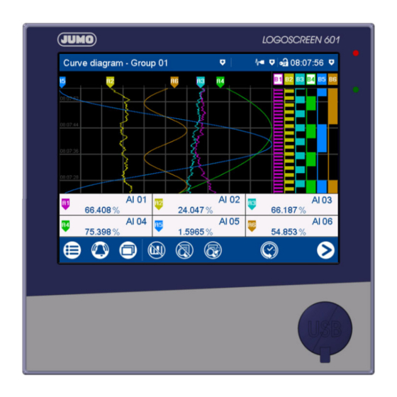
Summary of Contents for JUMO LOGOSCREEN 601
- Page 1 JUMO LOGOSCREEN 601/700 Bildschirmschreiber Paperless Recorder Baugruppen nachrüsten Retrofitting Modules 70653000T94Z000K000 V1.00/DE-EN/00717497...
- Page 3 JUMO LOGOSCREEN 601/700 Bildschirmschreiber Montageanleitung 70653000T94Z000K000 V1.00/DE/...
-
Page 4: Table Of Contents
Inhalt Inhalt Einleitung ............3 Sicherheitshinweise . -
Page 5: Einleitung
Einleitung 1 Einleitung Sicherheitshinweise Warnende Zeichen WARNUNG! Dieses Zeichen in Verbindung mit dem Signalwort weist darauf hin, dass ein Personenschaden eintre- ten kann, wenn die entsprechenden Vorsichtsmaßnahmen nicht getroffen werden. VORSICHT! Dieses Zeichen in Verbindung mit dem Signalwort weist darauf hin, dass ein Sachschaden oder ein Datenverlust auftritt, wenn die entsprechenden Vorsichtsmaßnahmen nicht getroffen werden. -
Page 6: Übersicht Der Baugruppen Und Steckplätze
1 Einleitung Übersicht der Baugruppen und Steckplätze HINWEIS! Dieses Dokument ergänzt die Kurzanleitung 70652100T97... bzw. 70653000T97... oder die Betriebsan- leitung 70652100T90... bzw. 70653000T90... (die Kurzanleitung gehört zum Lieferumfang des Geräts). Die dortigen Hinweise zur Montage und zum elektrischen Anschluss sind zu beachten. Die folgenden Baugruppen stehen zum Nachrüsten von optionalen Ein- und Ausgängen zur Verfügung. - Page 7 1 Einleitung Steckplätze (Slots) bei Typ 706530 Baugruppen für Typ 706530 Bezeichnung (Beschreibung) Teilenummer Verwendbar in (TN) Steckplatz (Slot) Analog/Digital: 3AI,6DI,1AO 00717130 1, 2, 3 (3 Analogeingänge, 6 Digitaleingänge, 1 Analogausgang) Analog(HI)/Digital: 3AI(HI),4DI,4DI/DO 00717131 1, 2, 3 (3 Analogeingänge mit erhöhter Spannungsfestigkeit, 4 Digital- eingänge, 4 Digitaleingänge/-ausgänge, einzeln umschaltbar) Analog: 6AI 00717168...
-
Page 8: Baugruppen Nachrüsten
Baugruppen nachrüsten 2 Baugruppen nachrüsten Gehäuse öffnen WARNUNG! Gefahr durch gefährliche elektrische Spannung Unsachgemäße Handhabung kann zu Personenschäden führen. Gerät vor dem Öffnen außer Betrieb nehmen und allpolig von der Stromversorgung trennen! VORSICHT! Gefahr durch unsachgemäße Handhabung Unsachgemäße Handhabung kann zu Schäden am Gerät oder zu Fehlfunktionen führen. ... -
Page 9: Rückwand Vorbereiten
2 Baugruppen nachrüsten Rückwand vorbereiten Typ 706521 Schritt Tätigkeit Nur für Baugruppe „Analog/Digital: 3AI,6DI,1AO“ (Slot 1 oder 2): Abdeckung (D) des betreffenden Steckplatzes (Slots) abziehen (vgl. Typ 706530). Nur für Baugruppe „Digital: 12DI/DO“ (Slot 3): Blechteile (F) mit Hilfe eines Schraubendrehers aus der Rückwand herausbrechen (Soll- bruchstellen). -
Page 10: Baugruppe Einsetzen Und Gehäuse Schließen
2 Baugruppen nachrüsten Baugruppe einsetzen und Gehäuse schließen Schritt Tätigkeit Baugruppe (G) in den betreffenden Steckplatz einschieben (Klemmleisten vorher abzie- hen). Rückwand (C) einsetzen. 2 Schrauben (B) einsetzen (davon eine Schraube mit Sicherungsscheibe) und mit einem Anzugsmoment von 0,8 bis 0,9 Nm festdrehen. Nur bei Typ 706530 und Baugruppe „Digital: 12DI/DO“... - Page 12 JUMO GmbH & Co. KG Moritz-Juchheim-Straße 1 Technischer Support Deutschland: 36039 Fulda, Germany Telefon: +49 661 6003-727 Telefon: +49 661 6003-9135 Telefax: +49 661 6003-508 Telefax: +49 661 6003-881899 E-Mail: mail@jumo.net E-Mail: service@jumo.net Internet: www.jumo.net Lieferadresse: Mackenrodtstraße 14 36039 Fulda, Germany...
- Page 13 JUMO LOGOSCREEN 601/700 Paperless Recorder Installation Instructions 70653000T94Z000K000 V1.00/EN/...
- Page 14 Contents Contents Introduction ........... . 3 Safety information .
-
Page 15: Introduction
Introduction 1 Introduction Safety information Warning symbols WARNING! This symbol in connection with the signal word indicates that personal injury may occur if the respective precautionary measures are not carried out. CAUTION! This symbol in connection with the signal word indicates that material damage or data loss will occur if the respective precautionary measures are not taken. -
Page 16: Overview Of Modules And Slots
1 Introduction Overview of modules and slots NOTE! This document supplements the quick start quide (brief instructions) 70652100T97... or 70653000T97... or the operating manual 70652100T90... or 70653000T90... (the quick start quide is included in the scope of delivery of the device). The instructions provided here for installation and electrical connection must be observed. - Page 17 1 Introduction Slots on type 706530 Modules for type 706530 Designation (description) Part no. (TN) Usable in slot Analog/digital: 3AI,6DI,1AO 00717130 1, 2, 3 (3 analog inputs, 6 digital inputs, 1 analog output) 00717131 1, 2, 3 Analog(HI)/digital: 3AI(HI),4DI,4DI/DO (3 analog inputs with increased electric strength, 4 digital inputs, 4 digital inputs/outputs, individually switchable) Analog: 6AI 00717168...
-
Page 18: Retrofitting Of Modules
Retrofitting of modules 2 Retrofitting of modules Opening the housing WARNING! Danger due to hazardous electrical voltage Incorrect handling may result in personal injury. Before opening, take the device out of operation and disconnect all poles from the power supply! CAUTION! Danger due to incorrect handling Incorrect handling may result in damage to the device or malfunctions. -
Page 19: Preparing The Back Panel
2 Retrofitting of modules Preparing the back panel Type 706521 Step Action Only for module "Analog/digital: 3AI,6DI,1AO" (slot 1 or 2): Remove the cover (D) of the relevant slot (see type 706530). Only for module "Digital: 12DI/DO" (slot 3): Use a screwdriver to break sheet metal parts (F) out of the back panel (predetermined breaking points). -
Page 20: Inserting The Module And Closing The Housing
2 Retrofitting of modules Inserting the module and closing the housing Step Action Insert the module (G) into the relevant slot (remove the terminal strips beforehand). Insert back panel (C). Insert 2 screws (B) (including one screw with locking washer) and tighten to a torque of 0.8 to 0.9 Nm. - Page 22 JUMO GmbH & Co. KG JUMO Instrument Co. Ltd. JUMO Process Control, Inc. Street address: JUMO House 6733 Myers Road Moritz-Juchheim-Straße 1 Temple Bank, Riverway East Syracuse, NY 13057, USA 36039 Fulda, Germany Harlow, Essex, CM20 2DY, UK Delivery address:...


Need help?
Do you have a question about the LOGOSCREEN 601 and is the answer not in the manual?
Questions and answers