
Related Manuals for JUMO B 90.7023.1


Summary of Contents for JUMO B 90.7023.1
- Page 1 Transducers for Humidity and Temperature for industrial applications B 90.7023.1 Operating Instructions 2009-03-09/00463148...
-
Page 3: Table Of Contents
Connections to a 24 VAC Power Supply ......33 Probe Mounting ..............35 General Instructions for Probes with a Cable ..... 36 907023/333 for Ducts and Tight Spaces ......38 907023/334 for High Pressure and Vacuum Applications .. 38 907023/335 for High Temperatures ........40 JUMO ________________________________________________________________________ 1... - Page 4 User's Guide _______________________________________________________________________ 907023/337 for High Humidity Applications ......41 Temperature Probe (Optional) ..........41 907023/338 for Pressurized Pipelines......... 41 Tightening the Clasp Nut ............. 43 Optional Modules..............44 Power Supply Module............44 Installation ..............45 Warnings ................ 46 Galvanic Isolation for Output ..........49 Third Analog Output ............
- Page 5 Data Recording ..............103 Selecting Data Recording Quantities ........ 103 DSEL ................103 View Recorded Data ............104 DIR ................104 PLAY ................105 Deleting the Recorded Files ..........107 UNDELETE ..............107 Analog Output Settings ............107 JUMO ________________________________________________________________________ 3...
- Page 6 User's Guide _______________________________________________________________________ Changing Output Mode and Range ........107 Analog Output Quantities ..........109 AMODE/ASEL .............. 110 Analog Output Tests ............111 ITEST ................111 Analog Output Fault Indication Setting ......112 AERR ................112 Operation of Relays .............. 113 Quantity for Relay Output ..........
- Page 7 Technical Specifications of Optional Modules ....153 Power Supply Module ..........153 Analog Output Module ..........153 Relay Module ............... 154 RS-485 Module ............154 LAN Interface Module ..........154 WLAN Interface Module ..........154 Data Logger Module............. 155 JUMO ________________________________________________________________________ 5...
- Page 8 User's Guide _______________________________________________________________________ Options and Accessories ............ 156 Dimensions (mm/inch) ............158 907023/331 ................ 159 907023/333 ................ 160 907023/334 ................ 160 907023/335 ................ 161 907023/337 ................ 161 907023/338 ................ 162 Temperature Probe 907023/337B ........162 APPENDIX A PROBE INSTALLATION KITS AND INSTALLATION EXAMPLES ..163 Duct Installation Kits (for 907023/333/337/335) ....
- Page 9 Board ..................71 Figure 47 Connection Example Between PC Serial Port and User Port .. 72 Figure 48 Network Interface Menu ............76 Figure 49 IP Configuration Menu .............. 76 Figure 50 Wireless LAN Settings .............. 79 JUMO ________________________________________________________________________ 7...
- Page 10 User's Guide _______________________________________________________________________ Figure 51 Entering Network SSID ............. 79 Figure 52 Selecting the Wireless Network Type ........79 Figure 53 Web Configuration Interface for WLAN ........82 Figure 54 Connecting Using Serial Interface ..........83 Figure 55 Connecting Using a Network ............ 83 Figure 56 Hyper Terminal Serial Port Settings .........
- Page 11 Selection of Output Modes ............98 Table 27 Filtering Levels ................. 99 Table 28 Error Messages ..............134 Table 29 Indicator Led Functions ............138 Table 30 Calculated Variables (Typical Ranges) ........149 Table 31 Transmitter Weight (in kg/lb) ..........153 JUMO ________________________________________________________________________ 9...
-
Page 12: General Information
This chapter provides general notes for the manual and the product. About This Manual This manual provides information for installing, operating, and maintaining JUMO Humidity and Temperature Transmitter Series 907023. Contents of This Manual This manual consists of the following chapters: - Chapter 1, General Information, provides general notes for the manual and the product. -
Page 13: General Safety Considerations
NOTE Note highlights important information on using the product. Feedback JUMO Customer Documentation Team welcomes your comments and suggestions on the quality and usefulness of this publication. If you find errors or have other suggestions for improvement, please indicate the chapter, section, and page number. You can send comments to us by e-mail: mail@jumo.net... -
Page 14: Product Related Safety Precautions
ESD Protection Electrostatic Discharge (ESD) can cause immediate or latent damage to electronic circuits. JUMO products are adequately protected against ESD for their intended use. However, it is possible to damage the product by delivering electrostatic discharges when touching, removing, or inserting any objects inside the equipment housing. -
Page 15: Transmitters With Wlan Interface
(e.i.r.p.) is not more than that permitted for successful communication. This Class [B] digital apparatus complies with Canadian ICES-003. Cet appareil numérique de la classe [B] est conforme à la norme NMB-003 du Canada. JUMO _______________________________________________________________________ 13... -
Page 16: Recycling
Corporation in the United States and/or other countries. License Agreement All rights to any software are held by JUMO or third parties. The customer is allowed to use the software only to the extent that is provided by the applicable supply contract or Software License Agreement. -
Page 17: Warranty
JUMO or its representatives with respect to any defect or deficiency applicable to or b) The allegedly defective Product or part shall, resulting directly or indirectly from the Products should JUMO so require, be sent to the works of supplied hereunder, which... -
Page 18: Chapter 2 Product Overview
User's Guide _______________________________________________________________________ CHAPTER 2 PRODUCT OVERVIEW This chapter introduces the features, advantages, and the product nomenclature of the JUMO Humidity and Temperature Transmitter Series 907023. Introduction to TRANSMITTER The transmitter provides reliable humidity measurement in a wide range of applications. Analog outputs can be chosen between current and voltage signals. -
Page 19: Basic Features And Options
- USB connectivity for service connections via the optional USB-RJ45 cable - Optional modules: - isolated power supply - power supply module - RS-422/485-module - LAN and WLAN interfaces - data logger module with real time clock - additional analog output module - relay module JUMO __________________________________________________________________________ 17... -
Page 20: Structure Of The Transmitter
User's Guide _______________________________________________________________________ Structure of the Transmitter 0604-005 Figure 1 Transmitter Body The numbers refer to Figure 1: Signal + powering cable gland Cable gland for optional module, or WLAN antenna connector Cable gland for optional module Cover screw (4 pcs) Display with keypad (optional) Cover LED 18 _______________________________________________________________________________... -
Page 21: Figure 2 Inside The Transmitter
(optional) Grounding connector Power supply module (optional) Relay, data logger, or analog output module (optional) Humidity probe cable Temperature probe cable (optional) 10 = Output isolation module (optional) 11 = Adjustment buttons (chemical purge buttons) with indicator JUMO __________________________________________________________________________ 19... -
Page 22: Probe Options
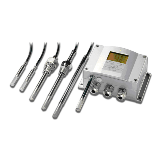
User's Guide _______________________________________________________________________ Probe Options 0507-033 Figure 3 Probe Options The following numbers refer to Figure 3: 907023/331 for demanding wall-mounted applications 907023/333 for ducts and tight spaces 907023/334 for high pressure and vacuum applications (up to 100 bars) 907023/335 for high temperatures (up to 180 ºC, vapor tight) *) Flange available as an option 907023/337 for high humidity applications (optional warmed and vapor tight probe) -
Page 23: Warmed Probe 907023/337
The warmed probe is heated continuously so that its temperature is always higher than in environment. This prevents condensation on the probe. The power consumption of the warmed probe is slightly higher than other probes. JUMO __________________________________________________________________________ 21... -
Page 24: Chapter 3 Installation
User's Guide _______________________________________________________________________ CHAPTER 3 INSTALLATION This chapter provides you with information that is intended to help you install the product. Mounting the Housing The housing can be mounted either without the mounting plate or with optional mounting plates. Standard Mounting without Mounting Plate Mount the housing by attaching the transmitter to a wall with 4 screws, for example M6 (not provided). -
Page 25: Wall Mounting With Wall Mounting Kit
Mount the plate to wall with 4 screws M6 (not provided) The arched side up Attach the transmitter to the mounting plate with 4 fixing screws M3 (provided) Holes for wall/junction box mounting 0804-065 Figure 6 Dimensions of the Plastic Mounting Plate (mm/inch) JUMO __________________________________________________________________________ 23... -
Page 26: Mounting With Din Rail Installation Kit
User's Guide _______________________________________________________________________ Mounting with DIN Rail Installation DIN rail installation kit includes a wall mounting kit, 2 clip-fasteners and 2 screws M4 × 10 DIN 7985. Attach two spring holders to the plastic mounting plate by using the screws provided in the installation kit. Attach the transmitter to the plastic mounting plate with the 4 screws provided for that purpose. -
Page 27: Pole Installation With Installation Kit For Pole Or Pipeline
The following numbers refer to Figure 8: Fixing brackets (2 pcs) M8 (provided) for 30 ... 102 mm poles. Mounting nuts M8 (4 pcs) 0503-007 Figure 9 Horizontal Pole The following number refers to Figure 9: Mounting nuts M8 (4 pcs) JUMO __________________________________________________________________________ 25... -
Page 28: Figure 10 Mounting With Metal Wall Mounting Plate
User's Guide _______________________________________________________________________ Metal mounting plate is included in rain shield with installation kit and installation kit for pole or pipeline. 0503-041 Figure 10 Mounting with Metal Wall Mounting Plate The following numbers refer to Figure 10: Mount the plate to wall with 4 screws M8 (not provided) Attach the transmitter to the mounting plate with 4 fixing screws M6 (provided) Note the position of the arrow when mounting. -
Page 29: Mounting Rain Shield With Installation Kit
Use the panel mounting frame as follows: Use the frame as a template to mark the required size for the installation hole in the panel. Cut the hole in the panel. Mount the transmitter through the panel with suitable supports. JUMO __________________________________________________________________________ 27... -
Page 30: Figure 13 Panel Mounting Frame
User's Guide _______________________________________________________________________ Remove the paper protecting the adhesive tape on the frame, and attach the frame around the transmitter. Refer to Figure 13 unterhalb. 0704-002 Figure 13 Panel Mounting Frame The following numbers refer to Figure 13: Panel (not included) Panel mounting frame 0804-083 Figure 14... -
Page 31: Wiring
When there is high electric noise level (for example, near a powerful NOTE electric motor) in the operating environment it is recommended to use shielded cable or take care that the signal cables are separated from other cables. JUMO __________________________________________________________________________ 29... -
Page 32: Grounding The Cables
User's Guide _______________________________________________________________________ Grounding the Cables Ground the screen of the electrical cable properly to achieve the best possible EMC performance. 0504-049 Figure 16 Grounding the Screen of Electrical Cable 30 _______________________________________________________________________________... -
Page 33: Grounding The Transmitter Housing
If it is needed to have galvanic isolation of the power supply line from the output signals, the transmitter can be ordered with an optional output isolation module. This module prevents harmful grounding loops. JUMO __________________________________________________________________________ 31... -
Page 34: Signal And Power Supply Wiring
User's Guide _______________________________________________________________________ Signal and Power Supply Wiring When connecting the transmitter with 8-pin connector, see section 8-Pin Connector on page 60. When wiring the power supply module, see section Power Supply Module on page 44. 0506-028 Figure 17 Screw Terminal Block on Motherboard The following numbers refer to Figure 17: Power supply terminals 10 ... -
Page 35: Connections To A 24 Vac Power Supply
To prevent fire and/or damage, if either 24 VAC wire is grounded or connected to a "-", "0", or "GND" terminal of any other device, you must connect the same wire on the "-" terminal also on this instrument. JUMO __________________________________________________________________________ 33... -
Page 36: Figure 18 Connections To 24 Vac Power Supply
User's Guide _______________________________________________________________________ 0703-041 Figure 18 Connections to 24 VAC Power Supply 34 _______________________________________________________________________________... -
Page 37: Probe Mounting
±1 °C between the environment and the probe causes an error of ±6 %RH. The graph below illustrates the measurement error at 100 %RH when the difference between the ambient and sensor temperature is 1 °C. 0507-023 Figure 19 Measurement Error at 100 %RH JUMO __________________________________________________________________________ 35... -
Page 38: General Instructions For Probes With A Cable
User's Guide _______________________________________________________________________ General Instructions for Probes with a Cable Mount the probes with a cable horizontally; this way, any water condensing on the tube cannot flow onto the sensor. 0507-024 Figure 20 Horizontal Mounting of Probe The following numbers refer to Figure 20: 1 = To be sealed. -
Page 39: Figure 21 Vertical Mounting Of Probe
If this is not possible and the probe must be inserted from the top, the point of entry must be carefully insulated. For JUMO probe installation kits and some installation examples, see Appendix A on page 163. JUMO __________________________________________________________________________ 37... -
Page 40: 907023/333 For Ducts And Tight Spaces
The 907023/333 is a small size (ø = 12mm) general-purpose probe suitable for ducts and channels with the installation kit available from JUMO. The 907023/333 provides for two measuring range options. The first probe version is equipped with a flexible cable and can be used when measuring in environments up to 80 ºC. -
Page 41: Figure 22 907023/334 Probe
Clean and grease the tightening cone of the fitting screw after every tenth detachment. Change the sealing washer every time the fitting screw is detached. Use high-vacuum grease (for example Dow Corning) or similar grease. JUMO __________________________________________________________________________ 39... -
Page 42: 907023/335 For High Temperatures
User's Guide _______________________________________________________________________ 0503-033 Figure 24 Cleaning of Tightening Cone The following numbers refer to Figure 24: Fitting screw Sealing washer Tightening cone Clean cotton stick CAUTION In pressurized processes it is essential to tighten the supporting nuts and screws very carefully to prevent loosening of the probe by the action of pressure. -
Page 43: 907023/337 For High Humidity Applications
Due to the sliding fit the 907023/338 is easy to install into and remove from the pressurized process. The probe is especially suitable for the measurements in pipelines. See section Ball Valve Installation Kit for 907023/338 on page 170. JUMO __________________________________________________________________________ 41... -
Page 44: Figure 25 907023/338 Probe
User's Guide _______________________________________________________________________ 0508-077 Figure 25 907023/338 Probe The following numbers refer to Figure 25: Clasp nut, 24 mm hex nut Fitting body, 27 mm hex head The following two fitting body options are available: - Fitting Body ISO1/2 solid structure - Fitting Body NPT1/2 solid structure Table 3 907023/338 Probe Dimensions... -
Page 45: Tightening The Clasp Nut
In pressurized processes it is essential to tighten the supporting nuts CAUTION and screws very carefully to prevent loosening of the probe by the action of pressure. JUMO __________________________________________________________________________ 43... -
Page 46: Optional Modules
User's Guide _______________________________________________________________________ NOTE When installed in a process with a pressure differing from normal atmospheric pressure, please enter the pressure value of the process (in hPa or mbar) into the transmitter memory via the serial line (see command PRES and XPRES on page 94) or by using display/keypad. -
Page 47: Installation
Do not detach the power supply module from the transmitter when the power is on. Do not connect the mains power to power supply module when it is WARNING not installed in the transmitter. WARNING Always connect the protective ground terminal. JUMO __________________________________________________________________________ 45... -
Page 48: Warnings
User's Guide _______________________________________________________________________ Warnings Dieses Produkt entspricht der Niederspannungsrichtlinie (73/23 EWG). Das Netzmodul darf nur von einem dazu befugten Elektriker angeschlossen werden. Trennen Sie das Netzmodul nicht vom Messwertgeber, wenn der Strom eingeschaltet ist. Verbinden Sie das Netzmodul nur mit der Spannungsquelle, wenn es im Messwertgeber 907023 montiert ist. - Page 49 Voolukaabli võib vooluallika mooduli külge ühendada ainult volitatud elektrik. Ärge ühendage vooluallika moodulit saatja küljest lahti, kui vool on sisse lülitatud. Ärge ühendage voolukaablit vooluallika mooduli külge, kui seda pole 907023-tüüpi saatjasse paigaldatud. Ühendage alati kaitsev maandusklemm! JUMO __________________________________________________________________________ 47...
- Page 50 User's Guide _______________________________________________________________________ Ez a termék megfelel a Kisfeszültségű villamos termékek irányelvnek (73/23/EGK). A hálózati feszültséget csak feljogosított elektrotechnikus csatlakoztathatja a tápegységmodulra. A bekapcsolt távadóról ne csatolja le a tápegységmodult. Ne csatlakoztassa a hálózati feszültséget a tápegységmodulhoz, ha az nincs beépítve a 907023 távadóba.
-
Page 51: Galvanic Isolation For Output
The following number refers to Figure 29: Output isolation module Third Analog Output 0503-030 Figure 30 Third Analog Output The following numbers refer to Figure 30: Flat cable pins Screw terminals for signal line DIP switches to select the output mode and range JUMO __________________________________________________________________________ 49... -
Page 52: Installation And Wiring
User's Guide _______________________________________________________________________ Installation and Wiring Disconnect the power. In case the analog output module is installed in the factory, continue with the step 4. Open the transmitter cover and fasten the analog output module to the position for MODULE 2 with four screws. Refer to Figure 2 on page 19. -
Page 53: Relays
C and NO outputs are closed, NC is open. For instructions on how to operate the relay (for example, select NOTE quantity for the relay output and set the relay setpoints) see section Operation of Relays on page 113. JUMO __________________________________________________________________________ 51... - Page 54 User's Guide _______________________________________________________________________ 0503-037 Figure 32 Relay Module The following numbers refer to Figure 32: Indication led for the relay 1 or 3 Relay test buttons Flat cable pins Indication led for relay 2 or 4 The relay module may contain dangerous voltages even if the WARNING transmitter power has been disconnected.
-
Page 55: Rs-422/485 Interface
Table 4 unterhalb: Table 4 Connecting the Twisted Pair Wires to the Screw Terminals Screw terminal Data line Data line (2-wire RS-485) (4-wire RS-485/422) (not connected) (not connected) Data pair shield Data pair shield JUMO __________________________________________________________________________ 53... -
Page 56: Figure 34 4-Wire Rs-485 Bus
User's Guide _______________________________________________________________________ If you use RS-485 (or RS-422) to connect just one transmitter to a master computer, enable the internal termination of transmitter by switching switches 1 and 2 ON. Make sure that the master's end of the line is also terminated (by using master's internal termination or with a separate terminator). -
Page 57: Lan Interface
The physical connection to the network is made to the RJ45 connector on the LAN interface module, using a standard twisted pair Ethernet cable (10/100Base-T). Transmitters with the optional LAN interface are delivered pre-installed with a suitable cable and cable gland. JUMO __________________________________________________________________________ 55... -
Page 58: Wlan Interface
User's Guide _______________________________________________________________________ The LAN interface can use both static and dynamic network settings. If the interface is configured to use dynamic settings, the network where the LAN interface is connected must have a DHCP server that provides the settings. The network configuration can be done using the optional display and keypad, or by using the service port. -
Page 59: Attaching The Wlan Antenna
Figure 74 on page 159. Data Logger Module The optional data logger module extends the data storage for the measurement data. When the data logger is present, this storage is automatically used by the transmitter. The stored data can be browsed JUMO __________________________________________________________________________ 57... - Page 60 User's Guide _______________________________________________________________________ using the optional display module, and accessed through the serial connections. See sections Graphic History on page 62 and Data Recording on page 103. The data logger module contains non-volatile flash memory providing 4 years 5 months of storage for 3 parameters at a 10 second sampling interval.
-
Page 61: Figure 37 Data Logger Module
The transmitter will also indicate the problem by activating the "Add-on module connection failure" error. If the module is not operating correctly, the transmitter must be sent to JUMO for maintenance. The data logger module must be installed at the factory (when ordering the transmitter. -
Page 62: 8-Pin Connector
User's Guide _______________________________________________________________________ 8-Pin Connector 0503-026 Figure 38 Wiring of Optional 8-Pin Connector Table 8 Wiring of 8-Pin Connector PIN/Terminal Wire Serial Signal Analog Signal RS-232 (EIA-232) RS-485 (EIA-485) White Data out TX Brown (serial GND) (serial GND) Signal GND (for both channels) Green Ch 2+... -
Page 63: Chapter 4 Operation
Basic Display Display shows you the measurement values of the selected quantities in the selected units. You can select 1 ... 3 quantities for the numerical basic display (see section Changing Quantities and Units on page 90.) JUMO __________________________________________________________________________ 61... -
Page 64: Graphic History
User's Guide _______________________________________________________________________ 0705-209 Figure 39 Basic Display The following numbers refer to Figure 39 oben: The Info shortcut button, see section Device Information on page 99 The Graph shortcut button, see section Graphic History on page 62 Quantities selected for display NOTE From any view, a four-second press on the right-hand function button takes you directly to the basic display. -
Page 65: Figure 41 Graphical Display With Data Logger
The new date will be displayed, and the cursor will be centered at the date where the cursor scrolled off the screen. 0706-030 Figure 41 Graphical Display with Data Logger JUMO __________________________________________________________________________ 63... -
Page 66: Menus And Navigation
User's Guide _______________________________________________________________________ The time that is shown below the graph is adjusted with the current time offset of the transmitter. If you change the transmitter's date and time setting, the displayed timestamps in the history graph change accordingly. For an explanation of the effect of changing the date and time manually, see section Data Logger Module on page 57. -
Page 67: Changing The Language
Scroll to the Language menu option, and the left-hand button. The menu option is indicated with the flag symbol. Select the language with the ▼▲ buttons, and confirm the selection by pressing the left-hand button. Press the right-hand button to exit to the basic display. JUMO __________________________________________________________________________ 65... -
Page 68: Rounding Setting
User's Guide _______________________________________________________________________ Rounding Setting Round off one decimal by using the Rounding function. The default setting is rounding on. Rounding has no effect on quantities without decimals. Open the MAIN MENU by pressing any of the ▼▲◄► arrow buttons. Select Display and confirm by pressing the ►arrow button. -
Page 69: Menu Pin Lock
Select Factory settings and press the REVERT button to confirm your selection. Press the YES button to reset all settings to the factory defaults. See section General Settings on page 90 for a description of the other menu options. JUMO __________________________________________________________________________ 67... -
Page 70: Display Alarms
User's Guide _______________________________________________________________________ Display Alarms The Display Alarm feature provides two independently configurable alarms for transmitters with the display/keypad option. Each alarm tracks a selected quantity, with a freely configurable low and high limit. Each alarm also has a configurable hysteresis value to prevent unnecessary triggering when the measurement fluctuates around an alarm limit. -
Page 71: Figure 44 Display Alarms
Set or clear the Alarm enable checkbox to enable or disable the alarm. Press the Exit button to leave the alarm configuration screen and return to the basic view. JUMO __________________________________________________________________________ 69... -
Page 72: Mi70 Link Program For Data Handling
COM port manually. The MI70 Link program, and the optional connection cables, are available from JUMO. See list of accessories in section Options and Accessories on page 156. Serial Line Communication Connect the serial interface by using either the user port or the service port. -
Page 73: User Port Connection
Use a suitable serial cable between the user port RxD, GND and TxD screw terminals and the PC serial port, see Figure 47 on page 72. Table 11 Default Serial Communication Settings for the User Port Parameter Value Bauds 4800 Parity Even Data bits Stop bits Flow control None JUMO __________________________________________________________________________ 71... -
Page 74: Service Port Connection
User's Guide _______________________________________________________________________ – Ch1+ 1 2 3 4 5 Ch1– 6 7 8 9 Ch2+ Ch2– IOIOI 0506-033 Figure 47 Connection Example Between PC Serial Port and User Port Connections to pins 4, 6, 7 and 8 on PC serial port are required only if you are using software requiring hardware handshaking. -
Page 75: Installing The Driver For The Usb Cable
Connect the desired cable (serial interface cable or USB cable) to your PC and the service port connector on the transmitter. For the location of the service port, refer to Figure 46 Seite 71. Open a terminal program and set the communication settings as follows: JUMO __________________________________________________________________________ 73... -
Page 76: Lan Communication
User's Guide _______________________________________________________________________ Table 12 Communication Settings for the Service Port Parameter Value Bauds 19200 Parity None Data bits Stop bits Flow control None For a detailed explanation of using a terminal program, see section Terminal Program Settings on page 76. Power-up the transmitter. -
Page 77: Using Display/Keypad
Press ► arrow button to select Network settings. There will be a delay as the transmitter refreshes the network information. You are now in the Network Interface menu. Selecting the IP configuration option opens the IP configuration menu. JUMO __________________________________________________________________________ 75... -
Page 78: Using Serial Line
User's Guide _______________________________________________________________________ 0802-113 Figure 48 Network Interface Menu The Network Interface menu also allows you to enable or disable the Web configuration option, or Disconnect all users that are currently accessing the LAN or WLAN interface. In the IP configuration menu, select Automatic configuration (DHCP), or enter the IP address, Netmask and Gateway manually. - Page 79 MAC address : 00:40:9d:2c:d2:05 Telnet : Not connected > >net on off DHCP : ON IP address : 192.168.0.104 Subnet mask : 255.255.255.0 Default gateway: 192.168.0.1 Web config. : OFF MAC address : 00:40:9d:2c:d2:05 Telnet : Connected > JUMO __________________________________________________________________________ 77...
-
Page 80: Wireless Lan Configuration
User's Guide _______________________________________________________________________ >net off 192.168.0.101 255.255.255.0 192.168.0.1 off DHCP : OFF IP address : 192.168.0.101 Subnet mask : 255.255.255.0 Default gateway: 192.168.0.1 Web config. : OFF MAC address : 00:40:9d:2c:d2:05 Telnet : Connected > Wireless LAN Configuration The settings of the WLAN interface are described in Table 14. The current settings can be viewed on the serial line or using the device information display;... -
Page 81: Figure 50 Wireless Lan Settings
SSID, and press the OK button. With the WEP encryption you must enter the encryption key in hexadecimal (10 hexdecimals for 64-bit encryption or 26 hexadecimals for 128-bit encryption). A WPA key must be 8 … 63 ASCII characters. JUMO __________________________________________________________________________ 79... -
Page 82: Using Serial Line
User's Guide _______________________________________________________________________ After setting the wireless network parameters, press the Exit button in the Wireless Network Settings menu. You will be asked to confirm the new settings. Note that when new settings are saved, all currently active WLAN connections are disconnected. -
Page 83: Telnet Settings
It also has additional options for advanced users. For example, there are more options for securing the wireless network. If these additional options are used, they will appear as custom configurations when viewed from the serial line or the display/keypad. JUMO __________________________________________________________________________ 81... -
Page 84: Figure 53 Web Configuration Interface For Wlan
User's Guide _______________________________________________________________________ 0802-114 Figure 53 Web Configuration Interface for WLAN Terminal Program Settings The following instructions show a connection example with ® HyperTerminal program for the Microsoft Windows operating system. NOTE HyperTerminal is not included with the Windows Vista operating system. -
Page 85: Figure 54 Connecting Using Serial Interface
If you are connecting using the LAN or WLAN interface, select TCP/IP (Winsock). Enter the IP address of the interface in the Host address field, and 23 as the Port number. Click OK to connect to the transmitter. 0709-007 Figure 55 Connecting Using a Network JUMO __________________________________________________________________________ 83... -
Page 86: Figure 56 Hyper Terminal Serial Port Settings
User's Guide _______________________________________________________________________ If you selected a serial port, you must match the port settings in the Properties window with the transmitter’s serial interface (user port or service port). If you are using the USB-RJ45 cable, you are connecting to the service port. Verify that Flow control is set to None. - Page 87 Display recorded files PLAY [0 ... 21] [START END] Output recorded data file. Start and end times can only be specified if the data logger module is installed. The times must be given in the following format: JUMO __________________________________________________________________________ 85...
- Page 88 User's Guide _______________________________________________________________________ Command Description yyyy-mm-dd hh:mm:ss DSEL Select data recording and display quantities. DELETE Delete all data files, including the memory of the optional data logger module UNDELETE Recover the deleted files that have not been overwritten Table 18 Chemical Purge Commands Command Description...
- Page 89 If a value is too long to fit to the allocated space in the output, or if there is an error in outputting the quantity, the value is displayed with stars ‘*’. Example: RH=***.* %RH T= 31.0 'C You can change the format of the output with the following commands: JUMO __________________________________________________________________________ 87...
- Page 90 User's Guide _______________________________________________________________________ - Outputting interval can be changed with the INTV command. - Output message format can be changed with the FORM command. - Status of chemical purge and probe heating can be added with the FST command. - Date and time information can be added with commands FDATE and FTIME Stopping Continuous Outputting Use the S command to end the RUN mode.
- Page 91 >fdate on Form. date : ON >send 2004-07-05 03:48:03 RH= 98.4 %RH T= 31.0 'C > To output the state of optional probe heating and chemical purge in connection with SEND and R commands enter: FST [x] JUMO __________________________________________________________________________ 89...
- Page 92 User's Guide _______________________________________________________________________ Where ON or OFF (default) Example: >fst on Form. status : ON >send 0 RH= 40.1 %RH T= 24.0 'C Td= 9.7 'C Tdf= 9.7 'C 8.7 g/m3 g/kg Tw= 15.6 'C ppm= 11980 pw= 12.00 hPa pws= 29.91 hPa h= 43.2 kJ/kg...
- Page 93 SEND and R. FORM [x] where Formatter string Formatter string consists of quantities and modifiers. When entering the command, use the abbreviations of the quantities. For more information on quantities, see Table 1 and Table 2 Seite 16. JUMO __________________________________________________________________________ 91...
- Page 94 User's Guide _______________________________________________________________________ The modifiers are presented in Table 23 unterhalb. Table 23 FORM Command Modifiers Modifier Description Length modifier (number of digits and decimal places) Tabulator Carriage-return Line feed “" String constant #xxx Special character, code "xxx" (decimal), for example #027 for ESC Unit field and length ADDR...
- Page 95 Pressure compensation is intended to be used in normal air only. When measuring in other gases. Using Display/Keypad Use display/keypad to set the pressure compensation. To select the pressure unit using display/keypad, see section Changing Quantities and Units on page 90. JUMO __________________________________________________________________________ 93...
- Page 96 User's Guide _______________________________________________________________________ Press any of the arrow buttons to open the MAIN MENU. Select Measuring and press the ►arrow button to confirm your selection. Select Pressure compensation and press the ►arrow button to confirm you selection. Press SET and enter the pressure value in the chosen unit by using the arrow buttons.
- Page 97 SEND commands, use the FTIME and FDATE commands. Example: >TIME Time : 13:42:49 ? >DATE Date : 2007-05-31 ? NOTE If the optional Data Logger Module is not installed, time and date are cleared to 2000-01-01 00:00:00 at reset or at power failure. JUMO __________________________________________________________________________ 95...
- Page 98 User's Guide _______________________________________________________________________ User Port Serial Settings Using Display/Keypad The communication settings for the user port can be changed via the serial line or by using the optional display/keypad. The communication settings for the service port are fixed and not changeable.
- Page 99 4800 O 7 1 >SERI 600 N 8 1 changing all parameters 600 N 8 1 > SMODE Use the command SMODE to set the user port start-up operating mode. SMODE [xxxx] where xxx = STOP, RUN or POLL JUMO __________________________________________________________________________ 97...
- Page 100 User's Guide _______________________________________________________________________ Table 25 Selection of Output Modes Mode Output Available Commands Only with the SEND command STOP All (default mode) Automatic output Only command S POLL Only with the SEND [addr] Use with RS-485 buses, see command Operation of the RS-485 Module on page 119.
- Page 101 = OFF, ON or EXT (default = OFF) Device Information Use the display/keypad or the serial line to display the device information. Press the INFO button in the basic display to see the following information: JUMO __________________________________________________________________________ 99...
-
Page 102: Figure 57 Device Information On Display
User's Guide _______________________________________________________________________ - Current sensor operation (for example, chemical purge), if any, in progress - Present or past unacknowledged errors, if any - Device information - Adjustment information fed by the user - Measuring settings - Information on chemical purge settings (when applicable) - Display Alarm settings - Serial interface information - Network settings and status of the LAN and WLAN interfaces... - Page 103 WLAN XPRES > ERRS Use the command ERRS to display transmitter error messages, see Table 27 on page 134. Example: >ERRS NO ERRORS > Example: >ERRS FAIL Error: Temperature measurement malfunction Error: Humidity sensor open circuit > JUMO _________________________________________________________________________ 101...
- Page 104 User's Guide _______________________________________________________________________ VERS Use the command VERS to display software version information. Example: >vers TRANSMITTER / 5.00 > Resetting Transmitter Using Serial Line RESET This command resets the device. The user port switches to start-up output mode selected with command SMODE. Locking Menu/Keypad by Using Serial Line LOCK...
- Page 105 Data recording quantity. See Table 1 on page 16 and Table 2 on page 17 for the quantities. Example: >dsel rh t tdf RH T Tdf > Enter the command without parameters and press ENTER to display the current recording parameters. JUMO _________________________________________________________________________ 103...
- Page 106 User's Guide _______________________________________________________________________ View Recorded Data If the device is provided with the optional display, the graphical display shows the data of the selected quantities, one at a time. See section Graphic History on page 62 for details about graphical display. You may also dump the logged data to the serial line in numeric form with the following commands.
- Page 107 = Ending date of the interval to be outputted. Must be given in the following format: yyyy-mm-dd end_time = Ending time of the interval to be outputted. Must be given in the following format: hh:mm:ss JUMO _________________________________________________________________________ 105...
- Page 108 User's Guide _______________________________________________________________________ Example: >play 3 2007-05-05 00:00:00 2007-05-06 00:00:00 (12 min intervals) 2007-05-05 00:00:00 Date Time trend yyyy-mm-dd hh:mm:ss 2007-05-05 00:00:00 19.16 18.99 19.33 2007-05-05 00:12:00 19.30 19.09 19.55 2007-05-05 00:24:00 20.01 19.28 21.17 2007-05-05 00:36:00 21.21 20.98 21.44 2007-05-05 00:48:00 19.57...
- Page 109 Third Analog Output on page 49. Changing Output Mode and Range Both output channels have their own DIP switch module with 8 switches; see the position in Figure 2 Seite 19 (DIP switches for analog output settings). JUMO _________________________________________________________________________ 107...
-
Page 110: Figure 58 Current/Voltage Switches Of Output Modules
User's Guide _______________________________________________________________________ Select the current/voltage output; switch ON either of the switches, 1 or 2. Select the range; switch ON one of the switches from 3 to 7. 0503-045 Figure 58 Current/Voltage Switches of Output Modules The following numbers refer to Figure 58 oben: Current/voltage selection output switches (from 1 to 2) Current/voltage range selection switches (from 3 to 7) in analog output 1 and 2. - Page 111 Select Output 1/2/3 by pressing the ► arrow button. Select Quantity by pressing the ▲▼ arrow buttons. Confirm your selection by pressing CHANGE. Select the quantity by using the arrow buttons. Press SELECT to confirm your selection. JUMO _________________________________________________________________________ 109...
- Page 112 User's Guide _______________________________________________________________________ Select Scale, lower limit, by pressing the ▲▼arrow buttons. Press SET to confirm your selection. Press OK to confirm your setting. Select the upper limit by pressing the ▲▼arrow buttons. Use the arrow buttons to set the upper limit value. Press SET to confirm your selection.
- Page 113 = Current or voltage value to be set for channel 2 (mA or V) Example: >itest 20 5 Ch1 (Td ) 20.000 mA H'672A Ch2 (T 5.000 mA H'34F9 >itest Ch1 (Td ) -23.204 'C 16.238 mA H'FFFE Ch2 (T 22.889 'C 8.573 mA H'5950 > JUMO _________________________________________________________________________ 111...
- Page 114 User's Guide _______________________________________________________________________ Analog Output Fault Indication Setting Factory default state for analog outputs during error condition is 0 V/ 0 mA. Please be careful when selecting the new error value. The error state of the transmitter should not cause unexpected problems in process monitoring.
-
Page 115: Figure 59 Measurement-Based Relay Output Modes
"below" value, the relay is passive when the measured value is not between the setpoints. You can also set only one setpoint. See Figure 59 unterhalb for illustrative examples of the different measurement-based relay output modes. 0610-076 Figure 59 Measurement-Based Relay Output Modes JUMO _________________________________________________________________________ 113... - Page 116 User's Guide _______________________________________________________________________ Mode 4 is usually used if an alarm needs to be triggered when the measured value exceeds a safe range. The relay is active when measurement is in range, and is released if the value goes out of range or the measurement fails.
-
Page 117: Figure 60 Fault/Online Status Relay Output Modes
FAULT/ONLINE STATUS relays are usually used in conjunction with an analog output to obtain validity information for the output value. NOTE If transmitter loses its power, all status-based relays are released similarly to the case of an instrument failure. JUMO _________________________________________________________________________ 115... -
Page 118: Figure 61 Relay Indicators On Display
User's Guide _______________________________________________________________________ Enabling/Disabling Relays You can deactivate the relay outputs for example for service purposes of your system. Setting Relay Outputs When having only one relay module installed, its relays are called NOTE 'relay 1' and 'relay 2'. When having two relay modules, the relays of the module connected to slot MODULE 1 are called 'relay 1' and relay 2' and relays connected to slot MODULE 2 are called 'relay 3' and 'relay 4' 0706-003... - Page 119 : 0.00 %RH ? 2 Rel1 RH enabl: OFF ? ON Rel2 T above: 0.00 'C ? 30 Rel2 T below: 0.00 'C ? 40 Rel2 T hyst : 0.00 'C ? 3 Rel2 T enabl: OFF ? ON > JUMO _________________________________________________________________________ 117...
- Page 120 User's Guide _______________________________________________________________________ Example of normal limit switch: Selecting relay 1 to follow relative humidity, relay 2 to follow temperature, relay 3 to follow dewpoint and relay 4 to follow dewpoint. One setpoint is chosen for all the outputs. >rsel rh t td td Rel1 RH above: 60.00 %RH ? 70 Rel1 RH...
- Page 121 The RS-485 interface enables communication between RS-485 network and 907023 transmitter. The RS-485 interface is isolated and offers a maximum communications rate of 115 200 bits/s. (For maximum bus length of 1 km, use bit rate 19200 b/s or less.) JUMO _________________________________________________________________________ 119...
- Page 122 User's Guide _______________________________________________________________________ When selecting an RS-232-RS-485 converter for the network, avoid self powered converters as they don't necessarily support the needed power consumption. Echo function shall be always disabled (OFF) when using the 2-wire connection. When using the 4-wire connection you can disable/enable the echo setting.
- Page 123 In POLL mode: measurements output only with command SEND [addr]. When several transmitters are connected to the same line, each transmitter must be entered an own address in the initial configuration, and POLL mode must be used. JUMO _________________________________________________________________________ 121...
- Page 124 User's Guide _______________________________________________________________________ INTV Use the INTV command to set the RUN mode output interval. INTV [n xxx] where 1 - 255 xxx = S, MIN or H This command sets the RUN mode output interval. The time interval is used only when the RUN mode is active. For example, the output interval is set to 10 minutes.
- Page 125 (0 ... 99) CLOSE The CLOSE command switches the transmitter back to the POLL mode. Example: >OPEN 2 (opens the line to transmitter 2, other transmitters stay in POLL mode) >CRH (for example, calibration performed) >CLOSE (line closed) JUMO _________________________________________________________________________ 123...
-
Page 126: Figure 62 Decrease Of Sensor Gain
User's Guide _______________________________________________________________________ Sensor Functions Chemical Purge (Optional) In some specific applications the sensor gain may decrease gradually due to an interference caused by a particular chemical present in the measured gas, for example. The decrease of sensor gain due to an interfering chemical and the effect of the chemical purge process are illustrated below, see Figure 62 unterhalb. - Page 127 Make sure that the temperature of the sensor has come down to normal temperature before starting a calibration. Chemical Purge in Power Up Chemical purge (start-up purge) can be set to start within 10 seconds from the power-up of the device. JUMO _________________________________________________________________________ 125...
-
Page 128: Figure 63 Purge Buttons On Motherboard
User's Guide _______________________________________________________________________ Starting and Configuring Chemical Purge Using Buttons on Motherboard PURGE Start manual chemical purge by pressing simultaneously two buttons on the motherboard inside the transmitter for a few seconds. Indicator led flashes until purge is complete (up to 6 minutes). 0508-011 Figure 63 Purge Buttons on Motherboard... -
Page 129: Figure 65 Performing Chemical Purge
720 min (=12 hours). In applications where the chemical exposure is not likely, the interval can be longer. It is not recommended to change duration, settling, temperature or temperature difference. JUMO _________________________________________________________________________ 127... - Page 130 User's Guide _______________________________________________________________________ Type PUR and press ENTER to proceed. The maximum interval is 14400 minutes (=10 days). Example: >pur Interval Purge : OFF ? Interval : 720 min ? Power-up Purge : OFF ? Duration : 120 s ? Settling : 240 s ? Temperature...
- Page 131 RH-limit and define the heating temperature and duration of this function. XHEAT Enables/disables the sensor heating. XHEAT [xx] where: xx = ON / OFF >xheat on Extra heat : ON >xheat off Extra heat : OFF > JUMO _________________________________________________________________________ 129...
- Page 132 User's Guide _______________________________________________________________________ To configure the sensor heating use the XHEAT command without parameters. Enter the values after question mark. The available ranges include the following: Extra heat RH -limit (heating 0 ... 100 %RH (default: 95 %RH) function starts-up above the setpoint) Extra heating temperature 0 ...
- Page 133 Install a new filter on the probe. When using the stainless steel filter (for oil and fuel cell), take care to tighten the filter properly (recommended force 5 Nm). New filters can be ordered from JUMO, see section Options and Accessories on page 156. JUMO _________________________________________________________________________ 131...
-
Page 134: Figure 66 Changing The Sensor
When replacing the sensor, the new sensor must be of the same type as the old sensor (for example, HUMICAP180R). The sensor type can only be changed at a JUMO Service Center. Remove the filter from the probe. See the instructions in section Changing the Probe Filter on page 131. -
Page 135: Figure 67 Error Indicator And Error Message
Press the INFO button to display the error message. You can also check the error message via the serial interface by using the command ERRS. In case of constant error, please contact JUMO. JUMO _________________________________________________________________________ 133... - Page 136 Clean the probes from dirt, water, ice or other contaminants. Internal ADC read error Internal transmitter failure. Remove the transmitter and return the faulty unit to JUMO Service. Additional temperature Check the integrity of the temperature probe sensor short circuit and the probe cable.
- Page 137 If the product needs repair, please follow the instructions below to speed up the process and to avoid extra costs to you. Read the section Warranty on page 15. Contact a JUMO Service. The latest contact information and instructions are available from www.JUMO.com. Please have the following information on hand:...
- Page 138 Pack the faulty product in a strong box of adequate size, with proper cushioning material to avoid damage. Include the information specified in step 2 in the box with the faulty product. Also include a detailed return address. Ship the box to the address specified by your JUMO contact. 136 ______________________________________________________________________________...
- Page 139 It is recommended that calibration and adjustment should be carried out by JUMO. Calibration and adjustment is carried out either by using the push-keys on the motherboard, through the serial port or with the optional display/keypad.
-
Page 140: Figure 68 Adjustment And Purge Buttons
User's Guide _______________________________________________________________________ 0508-013 Figure 68 Adjustment and Purge Buttons The following numbers refer to Figure 68 oben: Indicator led Adjustment button Press the purge buttons simultaneously to start chemical purge (if available) Adjustment menu is displayed only when ADJ button (on the motherboard inside the transmitter) is pressed. - Page 141 Insert the probe into a measurement hole of the 75 % RH (NaCl) reference chamber of the humidity calibrator. Wait at least 30 minutes for the sensor to stabilize (the indicator led is lit continuously). Adjustment cannot be done if the conditions are not stabilized (indicator led is flashing). JUMO _________________________________________________________________________ 139...
-
Page 142: Figure 70 Selecting Point 1 Reference Type
User's Guide _______________________________________________________________________ Press the button NaCl 75 % to adjust the 75 % RH condition. After adjustment transmitter returns to normal operation mode (indicator led is unlit). Using Display/Keypad Note that the difference between the two humidity references must be at least 50% RH. - Page 143 C and pressing ENTER. When stabilized, type the high end reference value after the question mark and press ENTER. >crh 11.25 Ref1 ? c 11.24 Ref1 ? c 11.24 Ref1 ? 11.3 Press any key when ready ... JUMO _________________________________________________________________________ 141...
- Page 144 User's Guide _______________________________________________________________________ 75.45 Ref2 ? c 75.57 Ref2 ? c 75.55 Ref2 ? c 75.59 Ref2 ? 75.5 > indicates that the adjustment has succeeded and the new calibration coefficients are calculated and stored. Enter the adjustment information (date and text) to the memory of the transmitter;...
- Page 145 ADJ key is pressed. Wait some time for the probe to reach ambient temperature. Remove the probe filter and insert the probe into the reference temperature. Enter the command CT or (CTA for additional T probe) and press ENTER. JUMO _________________________________________________________________________ 143...
- Page 146 User's Guide _______________________________________________________________________ or for additional T probe: Type C and press ENTER a few times to check if the reading is stabilized. Let the reading stabilize, give the reference temperature after the question mark and press ENTER three times. When using two reference temperatures (2-point calibration) press ENTER only twice and insert the probe to the second reference.
- Page 147 Enter the ACAL command and type the multimeter reading for each case. Continue by pressing ENTER. ACAL Example (current outputs): >ACAL Ch1 I1 (mA) ? 2.046 Ch1 I2 (mA) ? 18.087 Ch2 I1 (mA) ? 2.036 Ch2 I2 (mA) ? 18.071 > JUMO _________________________________________________________________________ 145...
- Page 148 User's Guide _______________________________________________________________________ Feeding Adjustment Information This information is shown on the device information fields (see section Device Information on page 99.) Using Display/Keypad If you are not in the adjustment menu, press the ADJ button on the motherboard (opens the ADJUSTMENT MENU). Select Adjustment info, press the ►...
- Page 149 (1.5 + 0.02 × reading) % RH Factory calibration uncertainty (+20 °C) ±0.6 % RH (0 ... 40 % RH) ±1.0 % RH (40 ... 97 % RH) (Defined as ± 2 standard deviation limits. Small variations possible, see also calibration certificate.) JUMO _________________________________________________________________________ 147...
-
Page 150: Figure 71 Accuracy Over Temperature Range
User's Guide _______________________________________________________________________ ® ® Response time (90 %) for HUMICAP 180, HUMICAP 180C and ® HUMICAP 180L2 at 20 °C in still air 8 s with grid filter 20 s with grid + steel netting filter 40 s with sintered filter ®... - Page 151 1.40 1.19 1.05 0.95 0.87 0.81 0.76 4.86 2.66 1.92 1.54 1.31 1.16 1.04 0.96 0.89 0.84 5.31 2.91 2.10 1.69 1.44 1.26 1.14 1.05 0.97 0.91 5.80 3.18 2.30 1.85 1.57 1.38 1.24 1.14 1.06 0.99 JUMO _________________________________________________________________________ 149...
- Page 152 User's Guide _______________________________________________________________________ Accuracy of Mixing Ratio g/kg (Ambient Pressure 1013 mbar) Relative humidity Temp. — — 0.003 0.003 0.003 0.003 0.003 0.004 0.004 0.004 — — 0.017 0.018 0.019 0.021 0.022 0.023 0.025 0.026 0.08 0.09 0.09 0.10 0.10 0.11 0.11 0.12...
-
Page 153: Figure 72 Accuracy In Dewpoint Measurement
-40 ... +60 °C (40 ... +140 °F) with display 0 ... +60 °C (+32 ... +140 °F) -55 … +80 °C (-67 … +176 °F) Storage temperature Electromagnetic compatibility EN61326-1:1997+ Am1:1998 + Am2:2001 Industrial environment JUMO _________________________________________________________________________ 151... - Page 154 User's Guide _______________________________________________________________________ Inputs and Outputs Operating voltage 10 ... 35 VDC, 24 VAC with optional power supply module 100 ... 240 VAC, 50/60 Hz Start-up time after power-up Power consumption @ 20 °C (Uin 24VDC) RS-232 max 25 mA Uout 2 ×...
- Page 155 0 ..1 V > 2000 ohms 0 ... 5 V and 0 ... 10 V > 10 000 ohms Storage temperature range -55 ... +80 °C (-67 ... +176 ºF) 3-pole screw terminal Max wire size 1.5 mm (AWG16) JUMO _________________________________________________________________________ 153...
- Page 156 User's Guide _______________________________________________________________________ Relay Module Operating temperature range -40 ... +60 ºC (-40 ... +140 ºF) Operating pressure range 500 ... 1300 mmHg Power consumption @ 24 V max 30 mA Contacts SPDT (change over), for example, Contact arrangement Form C Imax 0.5 A 250 VAC Imax...
- Page 157 13.7 million points / parameter Accuracy of the clock better than ±2 min/year Battery lifetime at -40 ... +30 ºC (-40 ... +86 ºF) 7 years at +30 ... +60 ºC (+86 ... +140 ºF) 5 years JUMO _________________________________________________________________________ 155...
- Page 158 User's Guide _______________________________________________________________________ Options and Accessories Description Item code Sales No. MODULES Relay Module RELAY-1 CALL Analog Output Module AOUT-1 CALL Isolated RS485 Module RS485-1 CALL Power Supply Module POWER-1 90/00502447 Galvanic Isolation Module DCDC-1 CALL SENSORS HUMICAP180 HUMICAP180 90/00446614 HUMICAP180L2 HUMICAP180L2 CALL...
- Page 159 CALL WINDOWS SOFTWARE Software Interface Kit 215005 90/00476419 OTHER HMK15 Calibration Adapter for 211302SP CALL 12 mm Probes with >7 mm Sensor Pins HMK15 Calibration Adapter for 218377SP CALL 12 mm Probes with <3 mm Sensor Pins JUMO _________________________________________________________________________ 157...
-
Page 160: Figure 73 Transmitter Body Dimensions
User's Guide _______________________________________________________________________ Dimensions (mm/inch) 0506-035 Figure 73 Transmitter Body Dimensions 158 ______________________________________________________________________________... -
Page 161: Figure 74 Wlan Antenna Dimensions
Chapter 7 _____________________________________________________________ Technical Data 0804-035 Figure 74 WLAN Antenna Dimensions 907023/331 12 (0.47) 0508-030 Figure 75 907023/331 Probe Dimensions JUMO _________________________________________________________________________ 159... -
Page 162: Figure 76 907023/333 Probe Dimensions
User's Guide _______________________________________________________________________ 907023/333 0804-060 Figure 76 907023/333 Probe Dimensions 907023/334 0804-059 Figure 77 907023/334 Probe Dimensions 160 ______________________________________________________________________________... -
Page 163: Figure 78 907023/335 Probe Dimensions
Chapter 7 _____________________________________________________________ Technical Data 907023/335 0508-020 Figure 78 907023/335 Probe Dimensions The flange is available as an option for the 907023/335 probe. 907023/337 0804-061 Figure 79 907023/337 Probe Dimensions JUMO _________________________________________________________________________ 161... -
Page 164: Figure 80 907023/338 Probe Dimensions
User's Guide _______________________________________________________________________ 907023/338 0508-078 Figure 80 907023/338 Probe Dimensions Temperature Probe 907023/337B 0804-062 Figure 81 Optional Temperature Probe Dimensions 162 ______________________________________________________________________________... -
Page 165: Figure 82 Duct Mounting Installation Kit
When the temperature difference between the duct and the air outside the NOTE duct is remarkable, the supporting bar must be installed as deep in the duct as possible. This prevents errors caused by the heat conduction in the bar and cable. JUMO _________________________________________________________________________ 163... -
Page 166: Figure 83 Duct Mounting Installation Kit For T-Probe
User's Guide _______________________________________________________________________ Duct Installation Kit for Temperature Probe (for 907023/337) JUMO duct installation kit for the T-probe includes flange, supporting bar, probe attaching part, sealing ring and the fixing screws (4 pcs). 0507-018 Figure 83 Duct Mounting Installation Kit for T-Probe... -
Page 167: Figure 84 Swagelok Installation Kit For Rh-Probe
P = max 10 bar max 30 mm T = max 180 ºC 1 2 3 0508-016 Figure 85 Swagelok Installation Kit for T-Probe The following numbers refer to Figure 85: T-probe Duct connector Swagelok connector Ferrules JUMO _________________________________________________________________________ 165... -
Page 168: Figure 86 Cable Installation With Cable Gland
Body and O-ring 0508-018 Figure 87 Probe Installation with Cable Gland Probe installation with cable gland is not available from JUMO. The following numbers refer to Figure 87: 1 = AGRO 1160.20.145 (T= -40 ... +100 ºC) Not available from JUMO. -
Page 169: Figure 88 Vapor Tight Installation
T- Probe Installations (907023/337) 0508-015 Figure 88 Vapor Tight Installation Vapor Tight Installation is not available from JUMO. The following numbers refer to Figure 88: Cable gland. For example AGRO 1100.12.91.065 (T= -25 ... +200 ºC) In pressurized processes, use a locking ring (example: 6x 0.7 DIN471) -
Page 170: Figure 90 Climate Chamber Installation
Cable gland, for example: AGRO 1100.12.91.065 Stainless steel cable tie or similar fastener To be sealed (silicone) Temperature probe Relative humidity probe HMP247CG, Cable gland AGRO (available from JUMO) NOTE Let the cables hang loosely to prevent condensed water running to the probe. 168 ______________________________________________________________________________... -
Page 171: Figure 91 Example Of Installation Through Roof
Plastic adapter to protect probes from condensation water coming from the pipe. Diameter slightly smaller than tube diameter. Plastic tube for probe (2 pcs) 10 = Stainless steel tube coming through the roof. 11 = Two thread bars holding the plastic adapter. 12 = Insulated pipe ending. JUMO _________________________________________________________________________ 169... -
Page 172: Figure 92 Installing The 907023/338 Probe Through A Ball Valve Assembly
User's Guide _______________________________________________________________________ Ball Valve Installation Kit for 907023/338 The ball valve installation kit (Order code: BALLVALVE-1) is preferred when connecting the probe to a pressurized process or pipeline. Use the ball valve set or a 1/2" ball valve assembly with a ball hole of ø14 mm or more. - Page 173 Tighten the clasp nut with a fork spanner a further 50 ... 60º (ca. 1/6 turn). If you have a suitable torque spanner, tighten the nut to max 45 ± 5 Nm (33 ± 4 ft-lbs). Refer to Figure 27 on page 43. JUMO _________________________________________________________________________ 171...
-
Page 174: Figure 93 Meteorological Installation Kit For Outdoor Installation
User's Guide _______________________________________________________________________ Take care not to tighten the clasp nut more than 60° to avoid NOTE difficulties when opening it. If you wish to remove the probe from the process, note that you have to pull the probe out far enough. You cannot close the valve if the groove on the probe body is not visible. - Page 175 0 ... 50 °C 6.1078 7.5000 237.3 50 ... 100 °C 5.9987 7.3313 229.1 100 ... 150 °C 5.8493 7.2756 225.0 150 ... 180 °C 6.2301 7.3033 230.0 1) Used for frostpoint calculation if the dewpoint is negative JUMO _________________________________________________________________________ 173...
- Page 176 User's Guide _______________________________________________________________________ Mixing ratio: Absolute humidity: Enthalpy: . 1 ( 00189 The water vapor saturation pressure P is calculated by using two equations (5 and 6): where: temperature in K C i = coefficients C 0 = 0.4931358 -0.46094296 * 10 -2 C 1 = 0.13746454 * 10 -4 C 2 =...
- Page 177 Parts per million by volume is calculated using: Symbols: dewpoint temperature (°C) water vapor pressure (hPa) water vapor saturation pressure (hPa) RH = relative humidity (%) mixing ratio (g/kg) atmospheric pressure (hPa) absolute humidity (g/m3) temperature (K) enthalpy (kJ/kg) JUMO _________________________________________________________________________ 175...
Need help?
Do you have a question about the B 90.7023.1 and is the answer not in the manual?
Questions and answers
Hello, for the JUMO B 90.7023.1 what voltage level is used for the RS-232 channel on the user port.