
Subscribe to Our Youtube Channel
Related Manuals for JCM GLOBAL UBA Pro Series


Summary of Contents for JCM GLOBAL UBA Pro Series
- Page 1 Website: http://www.jcmglobal.com Pro Series ™ Universal Banknote Acceptor Operation and Maintenance Manual (Revision A) P/N 960-000211R_Rev. A Issue #4116-SME-01-00 © 2020, JAPAN CASH MACHINE CO., LTD.
- Page 2 UBA™ Pro Series Universal Banknote Acceptor Operation and Maintenance Manual Issue #4116-SME-01-00 REVISION HISTORY Rev №. Date Reason for Update Feb. 3, 2020 Initial Release Electrical Current Symbol Direct Current: indicates Direct Current values on product labels. International Compliance • RoHS Directive •...
-
Page 3: Table Of Contents
UBA™ Pro Series Universal Banknote Acceptor Table of Contents Page 1 GENERAL INFORMATION ..................1-1 Description ........................1-1 UBA Pro Unit ........................1-1 Model Descriptions ......................1-2 Type Descriptions ......................1-2 Software Descriptions ....................1-2 Precautions........................1-2 User Cautions ........................1-3 Installation Cautions........................ - Page 4 UBA™ Pro Series Universal Banknote Acceptor Table of Contents Page Cash Box Lock Installation....................2-3 Unlock Procedure......................2-3 DIP Switch Configurations .................... 2-4 Denomination Acceptance Settings (DIP Switches at the front) ........2-4 SW1 and SW2 Configurations ..................2-4 Interface Settings (Sub Board 1) ....................2-4 Interface and Recycler Settings (Sub Board 2) ................
- Page 5 UBA™ Pro Series Universal Banknote Acceptor Table of Contents Page Japan Cash Machine Co., LTD. (HQ) ..................3-1 4 DISASSEMBLY/REASSEMBLY ................4-1 Tool Requirements......................4-1 UBA Pro and Cash Box Removal ................. 4-1 LED Light Module and Upper Bar Sensor Removal............ 4-1 Box Sensor Removal .....................
- Page 6 UBA™ Pro Series Universal Banknote Acceptor Table of Contents Page PB Motor Operation Time Test ..................6-12 Centering Motor Operation Time Test................6-13 Stacker Motor Operation Test ..................6-13 Entrance Motor Speed Test (Forward)................6-14 Entrance Motor Speed Test (Reverse) ................6-14 Entrance and Feed Motors Simultaneous Speed Test (Forward)........
- Page 7 UBA™ Pro Series Universal Banknote Acceptor Table of Contents Page UBA Pro Bottom Cover Exploded View ..............7-15 UBA Pro Bottom Cover Parts List .................. 7-15 8 INDEX ........................8-17 A TROUBLESHOOTING....................A-1 Introduction ........................A-1 Troubleshooting Overview.................... A-1 Fault Table Listings ....................... A-1 Standard and ICB Error and Reject Code Conditions ..........
- Page 8 THIS PAGE INTENTIONALLY LEFT BLANK P/N 960-000211R_Rev. A © 2020, JAPAN CASH MACHINE CO., LTD.
- Page 9 UBA™ Pro Series Universal Banknote Acceptor List of Figures Page Figure 1-1 UBA Pro Unit ..................... 1-1 Figure 1-2 Precautionary Symbols ..................1-2 Figure 1-3 Unacceptable Banknotes .................. 1-4 Figure 1-4 UBA Pro Component Names ................1-5 Figure 1-5 UBA Pro Unit With 500 Note Cash Box Outside Dimension ......1-8 Figure 1-6 UBA Pro Unit With Standard or ICB 900 Note Cash Box Outside Dimension ..
- Page 10 UBA™ Pro Series Universal Banknote Acceptor List of Figures Page Figure 4-19 Centering Motor Harness Assy. Removal 4 ............4-5 Figure 4-20 Entrance Motor Harness Assy. Removal ............4-5 Figure 4-21 Centering HP Board Removal 1 ................ 4-5 Figure 4-22 Centering HP Board Removal 2 ................
- Page 11 UBA™ Pro Series Universal Banknote Acceptor List of Figures Page Figure 6-26 Sensor Calibration 4 ..................6-6 Figure 6-27 Sensor Calibration 5 ..................6-6 Figure 6-28 Sensor Calibration 6 ..................6-6 Figure 6-29 Sensor Calibration 7 ..................6-6 Figure 6-30 Sensor Calibration 8 ..................
- Page 12 UBA™ Pro Series Universal Banknote Acceptor List of Figures Page Figure 6-78 Banknote Acceptance without Cash Box 2 ............. 6-17 Figure 6-79 Banknote Acceptance without Cash Box 3 ............. 6-17 Figure 6-80 Non-Validation Banknote Acceptance with Cash Box 1 ......... 6-18 Figure 6-81 Non-Validation Banknote Acceptance with Cash Box 2 .........
- Page 13 UBA™ Pro Series Universal Banknote Acceptor List of Figures Page Figure 6-130 Entrance Motor Operation Test (Reverse) 2 ........... 6-25 Figure 6-131 Entrance Motor Operation Test (Reverse) 3 ........... 6-25 Figure 6-132 Entrance Motor Operation Test (Reverse) 4 ........... 6-25 Figure 6-133 Entrance and Feed Motors Simultaneous Speed Test (Forward) 1 ....
- Page 14 THIS PAGE INTENTIONALLY LEFT BLANK P/N 960-000211R_Rev. A © 2020, JAPAN CASH MACHINE CO., LTD. x i i...
- Page 15 Table 1-5 UBA Pro Environmental Specifications.............. 1-7 Table 1-6 UBA Pro Electrical Specification ................ 1-7 Table 1-7 UBA Pro Series Structural Specification ............1-7 Table 2-1 Denomination Acceptance Settings ..............2-4 Table 2-2 Sub Board 1 Interface Settings ................2-4 Table 2-3 Sub Board 2 Interface Settings ................
- Page 16 THIS PAGE INTENTIONALLY LEFT BLANK P/N 960-000211R_Rev. A © 2020, JAPAN CASH MACHINE CO., LTD. x i v...
-
Page 17: Uba™ Pro Series
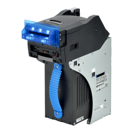
UBA™ Pro Series Universal Banknote Acceptor S e c t i o n 1 1 GENERAL INFORMATION Description In order to make operating this device and This section provides a general overview of the UBA™ Pro Series Universal Banknote Acceptor navigating within this manual easier, the following (UBA Pro), pictured in Figure 1-1. -
Page 18: Model Descriptions
1 = Standard Interface Harness 1 (No USB, UBA-1x Series Type) 2 = Standard Interface Harness 2 (1 USB, iPRO Series Type) (2)(3)(4) (6) (7) 3 = Standard Interface Harness 3 (2 USBs, UBA Pro Series Type) 5 = Reserved (1) Model Name (UBA Pro Series) 6 = Reserved... -
Page 19: User Cautions
General Information UBA™ Pro Series Universal Banknote Acceptor Section 1 Do not expose the unit to water. The unit 2. When reassembling a disassembled Unit Section, (Type 2) ensure that each part is properly replaced into its contains several precision electronic devices that can be damaged if water or any liquid is sprayed correct location. -
Page 20: Disposal Considerations
Section 1 UBA™ Pro Series Universal Banknote Acceptor General Information Primary Features This UBA Pro Series Banknote Acceptor Unit con- WARNING: Risk of explosion if battery is replaced by an incorrect type. tains the following primary features: • The UBA Pro Unit is backwards compatible with... -
Page 21: Component Names
General Information UBA™ Pro Series Universal Banknote Acceptor Section 1 Component Names Figure 1-4 illustrates the UBA Pro component names and locations. Figure 1-4 UBA Pro Component Names Standard Cash Box ICB Box Installation Type Stacking Up 500 Note 900 Note Standard (SS) 500 Note 900 Note... -
Page 22: Specifications
Section 1 UBA™ Pro Series Universal Banknote Acceptor General Information Specifications Technical Specifications Table 1-4 UBA Pro Technical Specification 98% or greater Note: The following banknote types are excluded: • Banknotes with excess or unclear graphics • Double (dual) Notes Acceptance Rate •... -
Page 23: Environmental Specifications
*. Measured on a new and factory default UBA Pro Unit. †. Use a Limited Power Source. Structural Specifications Table 1-7 UBA Pro Series Structural Specification Weight: UBA Pro Unit + Frame + Standard 500 Note Cash Box: Approximately 4kg (8.81lbs) Horizontal, 0 degrees, ±0 degrees angle... -
Page 24: Unit Dimensions
Section 1 UBA™ Pro Series Universal Banknote Acceptor General Information Unit Dimensions UBA Pro with Standard 500 Note Cash Box Outside Dimension Figure 1-5 illustrates the UBA Pro Unit with a Standard 500 Note Cash Box Outside Dimension. Figure 1-5 UBA Pro Unit With 500 Note Cash Box Outside Dimension 49.8 4xØ4 2xM3... -
Page 25: Uba Pro With Standard Or Icb 900 Note Cash Box Outside Dimension
General Information UBA™ Pro Series Universal Banknote Acceptor Section 1 UBA Pro with Standard or ICB 900 Note Cash Box Outside Dimension Figure 1-6 illustrates the UBA Pro Unit with a Standard or ICB 900 Note Cash Box Outside Dimension. Figure 1-6 UBA Pro Unit With Standard or ICB 900 Note Cash Box Outside Dimension 49.8 2xM3... -
Page 26: Uba Pro With Icb 500 Note Cash Box Outside Dimension
Section 1 UBA™ Pro Series Universal Banknote Acceptor General Information UBA Pro with ICB 500 Note Cash Box Outside Dimension Figure 1-7 illustrates the UBA Pro Unit with an ICB 500 Note Cash Box Outside Dimension. Figure 1-7 UBA Pro Unit With ICB 500 Note Cash Box Outside Dimension 49.8 4xØ4 2xM3... -
Page 27: Technical Contact Information
General Information UBA™ Pro Series Universal Banknote Acceptor Section 1 Technical Contact Information To obtain further technical information regarding the UBA Pro Unit, please contact the nearest location listed below: Americas Asia and Oceania JCM American JCM Gold (HK) Ltd. Phone: +1-702-651-0000 Phone: +852-2429-7187 Fax: +1-702-644-5512... - Page 28 Section 1 UBA™ Pro Series Universal Banknote Acceptor General Information THIS PAGE INTENTIONALLY LEFT BLANK P/N 960-000211R_Rev. A © 2020, JAPAN CASH MACHINE CO., LTD. 1 - 1 2...
-
Page 29: Installation
UBA™ Pro Series Universal Banknote Acceptor S e c t i o n 2 2 INSTALLATION 2. Tighten the Screw to secure the Wire and Washer. Figure 2-1 Grounding This section provides the installation and operating instructions for the UBA™ Pro Series Universal Banknote Acceptor (UBA Pro). -
Page 30: Rear Installation
Section 2 UBA™ Pro Series Universal Banknote Acceptor Installation Rear Installation Figure 2-4 Transport Stand Protector NOTE: Prepare the following Screws: • UNC6-32 Flat Head Screws • Tightening Torque: 120N·cm 1. Remove the UBA Pro Unit (Figure 2-3 a) and the Cash Box (Figure 2-3 b) from the Frame (Figure 2-3 c). -
Page 31: External Harness Installation
Installation UBA™ Pro Series Universal Banknote Acceptor Section 2 External Harness Installation Unlock Procedure Make sure lock(s) are installed and rotates in the NOTE: Prepare the following Screw: correct direction(s). • M3x12 Screw (provided) NOTE: When two locks are installed, they •... -
Page 32: Dip Switch Configurations
Section 2 UBA™ Pro Series Universal Banknote Acceptor Installation DIP Switch Configurations Interface Settings (Sub Board 1) The SW1 switch equipped on the Sub Board 1 is to Denomination Acceptance Settings set an interface RS232C or Photo-Coupler Isola- (DIP Switches at the front) tion (Table 2-2). -
Page 33: Led Light Flashing Pattern
Installation UBA™ Pro Series Universal Banknote Acceptor Section 2 LED Light Flashing Pattern The LED Color Pattern indications listed in Table 2-4 occur during various UBA Pro Unit operating and error conditions. Table 2-4 LED Light Flashing Pattern Red LED Green LED Sequence Condition... -
Page 34: Recommended Wire
Section 2 UBA™ Pro Series Universal Banknote Acceptor Installation Recommended Wire Caution: The wiring harness must be UL1061 AWG#22 with the specified length (the acceptable electrical resistance of a wire: Approximately 150mΩ). For 12V DC, the thinner or longer wiring harness than recommended specifications may cause the UBA Pro Unit to reset caused by voltage drop. -
Page 35: Connector Pin Assignment
Installation UBA™ Pro Series Universal Banknote Acceptor Section 2 Connector Pin Assignment NOTE: Refer to “SW1 and SW2 Configurations” on page 2-4 to determine the Interface settings on the CPU Circuit Board. Sub Board 1: USB Connector Pin Assignment Table 2-5 lists the UBA Pro Unit’s Sub Board 1 USB Connector Pin Assignments. Table 2-5 Sub Board 1 USB Connector Pin Assignments Rear View Socket (UBA Pro Side): DRA-20PC-FO (JAE) -
Page 36: Sub Board 1: Photo-Coupler Isolation Connector Pin Assignment
Section 2 UBA™ Pro Series Universal Banknote Acceptor Installation Sub Board 1: Photo-Coupler Isolation Connector Pin Assignment Table 2-6 lists the UBA Pro Unit’s Sub Board 1 Photo-Coupler Isolation Connector Pin Assignments. Table 2-6 Sub Board 1 Photo-Coupler Isolation Interface Pin Assignments Rear View Socket (UBA Pro Side): DRA-20PC-FO (JAE) Contact (UBA Pro Side) Pin No.1 and No.2: D02-22-22P-10000 (JAE) -
Page 37: Sub Board 1: Rs232C Connector Pin Assignment
Installation UBA™ Pro Series Universal Banknote Acceptor Section 2 Sub Board 1: RS232C Connector Pin Assignment Table 2-7 lists the UBA Pro Unit’s Sub Board 1 RS232C Connector Pin Assignments. Table 2-7 Sub Board 1 RS232C Connector Pin Assignments Rear View Socket (UBA Pro Side): DRA-20PC-FO (JAE) Contact (UBA Pro Side) Pin No.1 and No.2: D02-22-22P-10000 (JAE) Contact (UBA Pro Side) Pin No.3 - No.20:D02-22-26P-10000 (JAE) -
Page 38: Sub Board 1: Ttl Connector Pin Assignment
Section 2 UBA™ Pro Series Universal Banknote Acceptor Installation Sub Board 1: TTL Connector Pin Assignment Table 2-8 lists the UBA Pro Unit’s Sub Board 1 TTL Connector Pin Assignments. Table 2-8 Sub Board 1TTL Connector Pin Assignments Rear View Socket (UBA Pro Side): DRA-20PC-FO (JAE) Contact (UBA Pro Side) Pin No.1 and No.2: D02-22-22P-10000 (JAE) Contact (UBA Pro Side) Pin No.3 - No.20:D02-22-26P-10000 (JAE) -
Page 39: Sub Board 2: Usb Connector Pin Assignment
Installation UBA™ Pro Series Universal Banknote Acceptor Section 2 Sub Board 2: USB Connector Pin Assignment Table 2-9 lists the UBA Pro Unit’s Sub Board 2 USB Connector Pin Assignments. Table 2-9 Sub Board 2 USB Connector Pin Assignments Rear View Socket (UBA Pro Side): DRA-20PC-FO (JAE) Contact (UBA Pro Side) Pin No.1 and No.2: D02-22-22P-10000 (JAE) Contact (UBA Pro Side) Pin No.3 - No.20:D02-22-26P-10000 (JAE) -
Page 40: Sub Board 2: Photo-Coupler Isolation Connector Pin Assignment
Section 2 UBA™ Pro Series Universal Banknote Acceptor Installation Sub Board 2: Photo-Coupler Isolation Connector Pin Assignment Table 2-10 lists the UBA Pro Unit’s Sub Board 2 Photo-Coupler Isolation Connector Pin Assignments. Table 2-10 Sub Board 2 Photo-Coupler Isolation Interface Pin Assignments Rear View Socket (UBA Pro Side): DRA-20PC-FO (JAE) Contact (UBA Pro Side) Pin No.1 and No.2: D02-22-22P-10000 (JAE) -
Page 41: Sub Board 2: Rs232C Connector Pin Assignment
Installation UBA™ Pro Series Universal Banknote Acceptor Section 2 Sub Board 2: RS232C Connector Pin Assignment Table 2-11 lists the UBA Pro Unit’s Sub Board 2 RS232C Connector Pin Assignments. Table 2-11 Sub Board 2 RS232C Connector Pin Assignments Rear View Socket (UBA Pro Side): DRA-20PC-FO (JAE) Contact (UBA Pro Side) Pin No.1 and No.2: D02-22-22P-10000 (JAE) Contact (UBA Pro Side) Pin No.3 - No.20:D02-22-26P-10000 (JAE) -
Page 42: Sub Board 2: Cc-Talk Connector Pin Assignment
Section 2 UBA™ Pro Series Universal Banknote Acceptor Installation Sub Board 2: cc-Talk Connector Pin Assignment Table 2-12 lists the UBA Pro Unit’s Sub Board 2 cc-Talk Connector Pin Assignments. Table 2-12 Sub Board 2 cc-Talk Connector Pin Assignments Rear View Socket (UBA Pro Side): DRA-20PC-FO (JAE) Contact (UBA Pro Side) Pin No.1 and No.2: D02-22-22P-10000 (JAE) Contact (UBA Pro Side) Pin No.3 - No.20:D02-22-26P-10000 (JAE) -
Page 43: Sub Board 2: Ttl Connector Pin Assignment
Installation UBA™ Pro Series Universal Banknote Acceptor Section 2 Sub Board 2: TTL Connector Pin Assignment Table 2-13 lists the UBA Pro Unit’s Sub Board 2 TTL Connector Pin Assignments. Table 2-13 Sub Board 2 TTL Connector Pin Assignments Rear View Socket (UBA Pro Side): DRA-20PC-FO (JAE) Contact (UBA Pro Side) Pin No.1 and No.2: D02-22-22P-10000 (JAE) Contact (UBA Pro Side) Pin No.3 - No.20:D02-22-26P-10000 (JAE) -
Page 44: Preventive Maintenance
Section 2 UBA™ Pro Series Universal Banknote Acceptor Installation Preventive Maintenance Figure 2-13 Clearing a Banknote Jam Collecting Banknotes To collect Cash Box deposited Banknotes, perform the following steps: 1. Pull the Cash Box Handle to separate the Cash Box from the Frame Housing. 2. -
Page 45: Cleaning Procedure
Installation UBA™ Pro Series Universal Banknote Acceptor Section 2 Cleaning Procedure To clean the UBA Pro Unit, gently rub the Sensors or Rollers in the Banknote Path using a dry, soft, lint-free, Micro-fiber Cloth ONLY. To keep the UBA Pro Unit’s performance optimal, perform routine cleaning and maintenance: •... -
Page 46: Sensor And Roller Locations
Section 2 UBA™ Pro Series Universal Banknote Acceptor Installation Sensor and Roller Locations Figure 2-16 illustrates the UBA Pro Unit’s various sensors and rollers to clean. Table 2-15 lists the UBA Pro sensor type cleaning methods. Figure 2-16 UBA Pro Sensor and Roller Bottom View Figure 2-16 UBA Pro Sensor and Roller Locations Table 2-15 UBA Pro Sensors and Cleaning Methods... -
Page 53: Operational Flowcharts
Installation UBA™ Pro Series Universal Banknote Acceptor Section 2 Operational Flowcharts Initialization and Banknote Acceptance Flowchart Figure 2-22 depicts a typical UBA Pro Initialization and Banknote Acceptance flow process. Figure 2-22 UBA Pro Initialization and Banknote Acceptance Flowchart a) Apply Power to the Unit. b) Initializing C) Return from “Collecting”... -
Page 54: Validation Flowchart
Section 2 UBA™ Pro Series Universal Banknote Acceptor Installation Validation Flowchart Figure 2-23 depicts a typical UBA Pro Banknote Validation flow process. Figure 2-23 UBA Pro Validation Flowchart A) From “Initialize” Flowchart (Figure 2-22) a) Is the Banknote Authentic? b) Is the Banknote unacceptable (INHIBIT)? c) Retried the validation 2 times? *1 d) Denomination Signal Output D) To “Initialization”... -
Page 55: Collecting Flowchart
Installation UBA™ Pro Series Universal Banknote Acceptor Section 2 Collecting Flowchart Figure 2-24 depicts a typical UBA Pro Collecting Banknote flow process. Figure 2-24 UBA Pro Collecting Flowchart B) From “Validation” Flowchart (Figure 2-23) a) Collect the Banknote into the Cash Box b) Is the Cash Box full? C) To “Initialization”... - Page 56 Section 2 UBA™ Pro Series Universal Banknote Acceptor Installation THIS PAGE INTENTIONALLY LEFT BLANK P/N 960-000211R_Rev. A © 2020, JAPAN CASH MACHINE CO., LTD. 2 - 2 8...
-
Page 57: Communications
UBA™ Pro Series Universal Banknote Acceptor S e c t i o n 3 3 COMMUNICATIONS This section was intentionally left out due to a Non-Disclosure Agreement requirement. If this information is required, please contact the closest office location listed below: Americas Asia and Oceania JCM A... - Page 58 Section 3 UBA™ Pro Series Universal Banknote Acceptor Communications THIS PAGE INTENTIONALLY LEFT BLANK P/N 960-000211R_Rev. A © 2020, JAPAN CASH MACHINE CO., LTD. 3 - 2...
-
Page 59: Disassembly/Reassembly
UBA™ Pro Series Universal Banknote Acceptor S e c t i o n 4 4 DISASSEMBLY/REASSEMBLY This section provides disassembly and reassembly Figure 4-1 UBA Pro and Cash Box Removal instructions for the UBA™ Pro Series Universal Banknote Acceptor (UBA Pro). ①... -
Page 60: Box Sensor Removal
Section 4 UBA™ Pro Series Universal Banknote Acceptor Disassembly/Reassembly Box Sensor Removal Figure 4-3 LED Light Module and Upper Bar Sensor Removal 2 To remove the Box Sensor, proceed as follows: 1. Release the two (2) Locking Tabs (Figure 4-6 &... -
Page 61: Main Board Removal
Disassembly/Reassembly UBA™ Pro Series Universal Banknote Acceptor Section 4 2. Release the six (6) Locking Tabs (Figure 4-9 6. Remove the two (2) Screws (Figure 4-12 & through ), and remove the Side Cover L (Fig- ), and remove the Sub Board (Figure 4-12 b). ure 4-9 b). - Page 62 Section 4 UBA™ Pro Series Universal Banknote Acceptor Disassembly/Reassembly 3. Remove the six (6) Screws (Figure 4-15 3. Feed the Harness (Figure 4-17 a) out through the hole on the side of the Unit as illustrated. through ), and remove the Main Board (Figure 4-15 b).
-
Page 63: Entrance Motor Harness Assy. Removal
Disassembly/Reassembly UBA™ Pro Series Universal Banknote Acceptor Section 4 Centering HP Board Removal 6. Unplug the Motor Harness (Figure 4-19 a), and feed the Harness in through the hole on the side To remove the Centering HP Board, proceed as fol- of the Unit as illustrated. -
Page 64: Pb Encoder Hp Board Removal
Section 4 UBA™ Pro Series Universal Banknote Acceptor Disassembly/Reassembly PB Encoder HP Board Removal PB Motor Harness Assy. Removal To remove the PB Encoder HP Board, proceed as To remove the PB Motor Harness Assy., proceed as follows: follows: 1. Remove the two (2) Screws (Figure 4-24 &... -
Page 65: Figure 4-30 Stack Motor Harness Assy. Removal 1
Disassembly/Reassembly UBA™ Pro Series Universal Banknote Acceptor Section 4 Stack Motor Harness Assy. Transport Motor Harness Assy. Removal Removal To remove the Stack Motor Harness Assy., proceed To remove the Transport Motor Harness Assy., as follows: proceed as follows: 1. Remove the four (4) Screws (Figure 4-30 1. -
Page 66: Pdic Array Removal
Section 4 UBA™ Pro Series Universal Banknote Acceptor Disassembly/Reassembly Figure 4-35 Transport Motor Harness Assy. Figure 4-37 Transport Motor Harness Assy. Removal 3 Removal 5 Figure 4-37 Transport Motor Harness Assy. Removal 5 NOTE: For the wire routing when reassembling, ensure that both Orange Blue Cables are placed under the Motor... -
Page 67: Lower Bar Sensor Removal
Disassembly/Reassembly UBA™ Pro Series Universal Banknote Acceptor Section 4 Slide Roller Removal 3. Unplug the two (2) Connectors (Figure 4-40 & ), and remove the FPC Harness (Figure 4-40 b). To remove the Slide Roller, proceed as follows: Figure 4-40 PDIC Array Removal 3 1. - Page 68 Section 4 UBA™ Pro Series Universal Banknote Acceptor Disassembly/Reassembly THIS PAGE INTENTIONALLY LEFT BLANK P/N 960-000211R_Rev. A © 2020, JAPAN CASH MACHINE CO., LTD. 4 - 1 0...
-
Page 71: Calibration And Testing
UBA™ Pro Series Universal Banknote Acceptor S e c t i o n 6 6 CALIBRATION AND TESTING Installation Procedures This section provides Calibration and Performance Testing instructions for the UBA™ Pro Series Uni- Perform the following steps to install the “ JCM Tool versal Banknote Acceptor (UBA Pro). -
Page 72: Part 2 - Usb Drivers Installation
Section 6 UBA™ Pro Series Universal Banknote Acceptor Calibration and Testing Part 2 - USB Drivers Installation 5. Click the “Next>” Screen Button (Figure 6-4 a) when the “ ” Screen Destination Folder USB Drivers need to be installed on the PC before shown in Figure 6-4 appears. -
Page 73: Jcm Tool Suite Standard Edition Mode
Calibration and Testing UBA™ Pro Series Universal Banknote Acceptor Section 6 JCM Tool Suite Standard Edition 2. When upgrading the Software, set DIP Switches as below (Figure 6-11). Mode Figure 6-11 Software Download (Upgrade) 1 DIP Switches All OFF (Normal Mode) The following two (2) mode feature types exist in the “... -
Page 74: Figure 6-14 Software Download (Initial) 2
Section 6 UBA™ Pro Series Universal Banknote Acceptor Calibration and Testing When downloading the Software Program for the Figure 6-17 Software Download 5 first time, the Device Information will not appear (Figure 6-14). Figure 6-14 Software Download (Initial) 2 Figure 6-14 Software Download (Initial) 2 Figure 6-17 Software Download 5 8. -
Page 75: Calibration
Calibration and Testing UBA™ Pro Series Universal Banknote Acceptor Section 6 Calibration 3. Firmly close the Upper Guide (Figure 6-22 a) until it “clicks” in place, and ensure that both This section provides instructions for performing a sides are tightly closed and locked. calibration of the UBA Pro Sensors. - Page 76 Section 6 UBA™ Pro Series Universal Banknote Acceptor Calibration and Testing 9. Confirm that the Sensor Calibration Program 13. The Sensor Calibration will pause before the Screen appears (Figure 6-25). “With Paper” calibration. 10. Click the “ ” button (Figure 14.
- Page 77 Calibration and Testing UBA™ Pro Series Universal Banknote Acceptor Section 6 19. The Sensor Calibration will pause when the Figure 6-34 Sensor Calibration 12 “With Paper” calibration is completed. 20. Lift up on the Upper Guide Access Lever to open the UBA Pro’s Cover (Figure 6-31 a).
-
Page 78: Performance Test Using A Pc
Section 6 UBA™ Pro Series Universal Banknote Acceptor Calibration and Testing Performance Test Using a PC 8. Select “ ” (Figure 6-39 a). Performance Test Figure 6-39 Launch Performance Test Program List of UBA Pro Performance Tests Table 6-1 lists the test items for the UBA Pro Unit Performance Test using a PC. -
Page 79: Banknote Acceptance Test Without Cash Box
Calibration and Testing UBA™ Pro Series Universal Banknote Acceptor Section 6 Banknote Acceptance Test without Non-Validation Banknote Acceptance Cash Box Test without Cash Box To perform the Acceptance Test validating Banknotes To perform the Acceptance Test not validating without the Cash Box, proceed as follows: Banknotes without the Cash Box, proceed as follows: 1. -
Page 80: Feed Motor Speed Test (Forward)
Section 6 UBA™ Pro Series Universal Banknote Acceptor Calibration and Testing Feed Motor Speed Test (Forward) Feed Motor Speed Test (Reverse) To perform the Feed Motor Speed Test in the forward To perform the Feed Motor Speed Test in the reverse rotation, proceed as follows: rotation, proceed as follows: 1. -
Page 81: Sensor Test
Calibration and Testing UBA™ Pro Series Universal Banknote Acceptor Section 6 Sensor Test Aging Test To perform the Sensor detection test, proceed as fol- To perform the Aging Test, proceed as follows: lows: 1. Ensure that the Cash Box is properly installed. 1. -
Page 82: Stacker Motor Operation Time Test
Section 6 UBA™ Pro Series Universal Banknote Acceptor Calibration and Testing PB Motor Operation Time Test 5. The resulting indication will appear in the “ ” area (Figure 6-55 a) on the Screen. switch To perform the PB Motor Operation Time Test, proceed 6. -
Page 83: Centering Motor Operation Time Test
Calibration and Testing UBA™ Pro Series Universal Banknote Acceptor Section 6 Centering Motor Operation Time Test Stacker Motor Operation Test To perform the Centering Motor Operation Time Test, To perform the Stacker Motor Operation Test without proceed as follows: the Cash Box, proceed as follows: 1. -
Page 84: Entrance Motor Speed Test (Forward)
Section 6 UBA™ Pro Series Universal Banknote Acceptor Calibration and Testing Entrance Motor Speed Test (Forward) Entrance Motor Speed Test (Reverse) To perform the Entrance Motor Speed Test in the for- To perform the Entrance Motor Speed Test in the ward rotation, proceed as follows: reverse rotation, proceed as follows: 1. -
Page 85: Entrance And Feed Motors Simultaneous Speed Test (Forward)
Calibration and Testing UBA™ Pro Series Universal Banknote Acceptor Section 6 Entrance and Feed Motors Entrance and Feed Motors Simultaneous Speed Test (Forward) Simultaneous Speed Test (Reverse) To perform the Speed Test of the Entrance Motor and To perform the Speed Test of the Entrance Motor and the Feed Motor in the forward rotation at the same time, the Feed Motor in the reverse rotation at the same time, proceed as follows:... -
Page 86: Performance Test Without A Pc
Section 6 UBA™ Pro Series Universal Banknote Acceptor Calibration and Testing Performance Test without a PC List of the Performance Tests without a PC Table 6-2 lists the items and DIP Switch settings for the Performance Test using DIP Switches without a Table 6-2 Performance Tests without a PC and DIP Switch Settings DIP Switches Test Item and Purpose... -
Page 87: Banknote Acceptance With Cash Box
Calibration and Testing UBA™ Pro Series Universal Banknote Acceptor Section 6 Banknote Acceptance with Cash Box Banknote Acceptance without Cash To perform the Acceptance Test with the Cash Box, proceed as follows: To perform the Acceptance Test without the Cash Box, proceed as follows: 1. -
Page 88: Non-Validation Banknote Acceptance With Cash Box
Section 6 UBA™ Pro Series Universal Banknote Acceptor Calibration and Testing Non-Validation Banknote Acceptance Non-Validation Banknote Acceptance with Cash Box without Cash Box To perform the Non-Validation Acceptance Test To perform the Non-Validation Acceptance Test with the Cash Box, proceed as follows: without the Cash Box, proceed as follows: 1. -
Page 89: Non-Validation Banknote Reject Test With Cash Box
Calibration and Testing UBA™ Pro Series Universal Banknote Acceptor Section 6 Non-Validation Banknote Reject Test Feed Motor Operation Test (Forward) with Cash Box To perform the Feed Motor Operation Test in the for- ward rotation, proceed as follows: To perform the Banknote Reject Test with the Cash 1. -
Page 90: Feed Motor Operation Test (Reverse)
Section 6 UBA™ Pro Series Universal Banknote Acceptor Calibration and Testing Feed Motor Operation Test (Reverse) Sensor Test To perform the Sensor Test, proceed as follows: To perform the Feed Motor Operation Test in the for- ward rotation, proceed as follows: 1. -
Page 91: Aging Test With Cash Box
Calibration and Testing UBA™ Pro Series Universal Banknote Acceptor Section 6 Aging Test with Cash Box Sensor/ Procedure and Confirmation To perform the Aging Test with the Cash Box, pro- Mechanism ceed as follows: (1) DIP Switch #2 ON 1. Remove electrical power. 2. -
Page 92: Stacking Operation Test
Section 6 UBA™ Pro Series Universal Banknote Acceptor Calibration and Testing Stacking Operation Test 3. Apply electrical power. 4. Confirm that the Green Status LEDs are To perform the Stacking Operation Test, proceed as lit. follows: Figure 6-104 DI Green Red 1. -
Page 93: Pb Motor Operation Test
Calibration and Testing UBA™ Pro Series Universal Banknote Acceptor Section 6 PB Motor Operation Test Centering Motor Operation Test To perform the PB Motor Operation Test, proceed as To perform the Centering Motor Operation Test, pro- follows: ceed as follows: 1. -
Page 94: Stacker Motor Operation Test
Section 6 UBA™ Pro Series Universal Banknote Acceptor Calibration and Testing Stacker Motor Operation Test Entrance Motor Operation Test (For- ward) To perform the Stacker Motor Operation Test without the Cash Box, proceed as follows: To perform the Entrance Motor Operation Test in the 1. -
Page 95: Entrance Motor Operation Test (Reverse)
Calibration and Testing UBA™ Pro Series Universal Banknote Acceptor Section 6 Entrance and Feed Motors Entrance Motor Operation Test (Reverse) Simultaneous Operation Test (For- ward) To perform the Entrance Motor Operation Test in the reverse rotation, proceed as follows: To perform the Motor Operation Test of the Entrance 1. -
Page 96: Entrance And Feed Motors Simultaneous Operation Test (Reverse)
Section 6 UBA™ Pro Series Universal Banknote Acceptor Calibration and Testing Entrance and Feed Motors Simultaneous Operation Test (Reverse) To perform the Motor Operation Test of the Entrance Motor and the Feed Motor in the reverse rotation at the same time, proceed as follows: 1. -
Page 97: Exploded Views And Parts Lists
UBA™ Pro Series Universal Banknote Acceptor S e c t i o n 7 7 EXPLODED VIEWS AND PARTS LISTS This section provides product Exploded Views and • UBA Pro Entire Unit Exploded View Parts Lists for the UBA™ Pro Series Universal •... -
Page 98: Uba Pro Entire Unit Parts List
Standard Interface Harness 2 (3630-05-011) iPRO Series Type 2 USBs 283356 Standard Interface Harness 3 (3630-05-012) UBA Pro Series Type 006037 3x12 Pan Head W Washer Small, Iron/Chromium (III) P/N 960-000211R_Rev. A © 2020, JAPAN CASH MACHINE CO., LTD. 7 - 2... -
Page 99: Uba Pro Upper Transport Guide Exploded View
Exploded Views and Parts Lists UBA™ Pro Series Universal Banknote Acceptor Section 7 UBA Pro Upper Transport Guide Exploded View Figure 7-2 UBA Pro Upper Transport Guide Exploded View Middle Bracket 108 109 Figure 7-2 UBA Pro Upper Transport Guide Exploded View P/N 960-000211R_Rev. -
Page 100: Uba Pro Upper Transport Guide Parts List
Section 7 UBA™ Pro Series Universal Banknote Acceptor Exploded Views and Parts Lists UBA Pro Upper Transport Guide Parts List Table 7-2 UBA Pro Upper Transport Guide Parts List Ref No. EDP No. Description Remark 280245 Upper Transport GUIDE 279832 φ9 Idle Roller 236947 φ9 Idle Roller Bracket... -
Page 101: Uba Pro Transport Unit Exploded View 1
Exploded Views and Parts Lists UBA™ Pro Series Universal Banknote Acceptor Section 7 UBA Pro Transport Unit Exploded View 1 Figure 7-3 UBA Pro Transport Unit Exploded View 1 220 216 230 Figure 7-3 UBA Pro Transport Unit Exploded View 1 P/N 960-000211R_Rev. -
Page 102: Uba Pro Transport Unit Parts List 1
Section 7 UBA™ Pro Series Universal Banknote Acceptor Exploded Views and Parts Lists UBA Pro Transport Unit Parts List 1 Table 7-3 UBA Pro Transport Unit Parts List 1 Ref No. EDP No. Description Remark 274212 ST Gear Cover 274293 PB Home Kick Spring 274226 PB Home Lever... -
Page 103: Uba Pro Transport Unit Exploded View 2
Exploded Views and Parts Lists UBA™ Pro Series Universal Banknote Acceptor Section 7 UBA Pro Transport Unit Exploded View 2 Figure 7-4 UBA Pro Transport Unit Exploded View 2 Figure 7-4 UBA Pro Transport Unit Exploded View 2 UBA Pro Transport Unit Parts List 2 Table 7-4 UBA Pro Transport Unit Parts List 2 Ref No. -
Page 104: Uba Pro Transport Unit Exploded View 3
Section 7 UBA™ Pro Series Universal Banknote Acceptor Exploded Views and Parts Lists UBA Pro Transport Unit Exploded View 3 Figure 7-5 UBA Pro Transport Unit Exploded View 3 Figure 7-5 UBA Pro Transport Unit Exploded View 3 UBA Pro Transport Unit Parts List 3 Table 7-5 UBA Pro Transport Unit Parts List 3 Ref No. -
Page 105: Uba Pro Transport Unit Exploded View 4
Exploded Views and Parts Lists UBA™ Pro Series Universal Banknote Acceptor Section 7 UBA Pro Transport Unit Exploded View 4 Figure 7-6 UBA Pro Transport Unit Exploded View 4 502 511 Figure 7-6 UBA Pro Transport Unit Exploded View 4 UBA Pro Transport Unit Parts List 4 Table 7-6 UBA Pro Transport Unit Parts List 4 Ref No. -
Page 106: Uba Pro Transport Unit Exploded View 5
Section 7 UBA™ Pro Series Universal Banknote Acceptor Exploded Views and Parts Lists UBA Pro Transport Unit Exploded View 5 Figure 7-7 UBA Pro Transport Unit Exploded View Figure 7-7 UBA Pro Transport Unit Exploded View 5 P/N 960-000211R_Rev. A ©... -
Page 107: Uba Pro Transport Unit Parts List 5
Exploded Views and Parts Lists UBA™ Pro Series Universal Banknote Acceptor Section 7 UBA Pro Transport Unit Parts List 5 Table 7-7 UBA Pro Transport Unit Parts List 5 Ref No. EDP No. Description Remark 274200 Centering Guide R Assy. 274199 Centering Guide L Assy. -
Page 108: Uba Pro Transport Unit Exploded View 6
Section 7 UBA™ Pro Series Universal Banknote Acceptor Exploded Views and Parts Lists UBA Pro Transport Unit Exploded View 6 Figure 7-8 UBA Pro Transport Unit Exploded View 6 Figure 7-8 UBA Pro Transport Unit Exploded View 6 UBA Pro Transport Unit Parts List 6 Table 7-8 UBA Pro Transport Unit Parts List 6 Ref No. -
Page 109: Uba Pro Middle Bracket Exploded View
Exploded Views and Parts Lists UBA™ Pro Series Universal Banknote Acceptor Section 7 UBA Pro Middle Bracket Exploded View Figure 7-9 UBA Pro Middle Bracket Figure 7-9 UBA Pro Middle Bracket Exploded View P/N 960-000211R_Rev. A © 2020, JAPAN CASH MACHINE CO., LTD. 7 - 1 3... -
Page 110: Uba Pro Middle Bracket Parts List
Section 7 UBA™ Pro Series Universal Banknote Acceptor Exploded Views and Parts Lists UBA Pro Middle Bracket Parts List Table 7-9 UBA Pro Middle Bracket Parts List Ref No. EDP No. Description Remark 280247 CPU Board Cover 274365 Entrance Motor Harness Assy. (4116-3630-03-001x) Service Part 280250 Entrance Motor END... -
Page 111: Uba Pro Bottom Cover Exploded View
Exploded Views and Parts Lists UBA™ Pro Series Universal Banknote Acceptor Section 7 UBA Pro Bottom Cover Exploded View Figure 7-10 UBA Pro Bottom Cover Exploded View Figure 7-10 UBA Pro Bottom Cover Exploded View UBA Pro Bottom Cover Parts List Table 7-10 UBA Pro Bottom Cover Parts List Ref No. - Page 112 Section 7 UBA™ Pro Series Universal Banknote Acceptor Exploded Views and Parts Lists THIS PAGE INTENTIONALLY LEFT BLANK P/N 960-000211R_Rev. A © 2020, JAPAN CASH MACHINE CO., LTD. 7 - 1 6...
-
Page 113: Index
UBA™ Pro Series Universal Banknote Acceptor S e c t i o n 8 8 INDEX Primary Features UBA-5x0 ...1-4 UBA Pro Series of Banknote Jam clearing a ...2-16 Safety pictographs indicating Cleaning ...1-1 1 to 3 symbols inside boxed area methods of, and equipment required for ...2-17... - Page 114 Section 8 UBA™ Pro Series Universal Banknote Acceptor Index THIS PAGE INTENTIONALLY LEFT BLANK P/N 960-000211R_Rev. A © 2020, JAPAN CASH MACHINE CO., LTD. 8 - 1 8...
-
Page 115: A Troubleshooting
UBA™ Pro Series Universal Banknote Acceptor A p p e n d i x A A TROUBLESHOOTING This section provides Troubleshooting instructions This observation is important in locating any fail- for the UBA™ Pro Series Universal Banknote ure causes and the possible fault area. If the Accep- Acceptor (UBA Pro). - Page 116 Appendix A UBA™ Pro Series Universal Banknote Acceptor Troubleshooting Table A-1 General Fault Conditions (Continued) Symptoms/Error Possible Fault Causes Corrective Action Required Messages The Acceptor Unit is not properly seated all the way into the Frame Reseat the Acceptor Unit back into the Frame and confirm the Acceptor Unit Release Lever Latches securely lock onto the Frame.
- Page 117 Troubleshooting UBA™ Pro Series Universal Banknote Acceptor Appendix A Table A-1 General Fault Conditions (Continued) Symptoms/Error Possible Fault Causes Corrective Action Required Messages Incorrect DIP Switch settings Set DIP Switch No. 8 to ON, and reapply Power to the UBA Pro Unit. Conduct a DIP Switch Test to check if the specific DIP Switch Can not enter the Dip Switch failure...
-
Page 118: Standard And Icb Error And Reject Code Conditions
Appendix A UBA™ Pro Series Universal Banknote Acceptor Troubleshooting Standard and ICB Error and Reject Code Conditions The two (2) Status LEDs (Red and Green) indicates various combinations of solid or alternating Color light flashing conditions when any of the Standard and ICB Error Codes listed in Table A-4 and Table A-5 occur respectively. - Page 119 Troubleshooting UBA™ Pro Series Universal Banknote Acceptor Appendix A Table A-4 Standard LED Error Codes (Continued) Green Relative Standard Errors Solutions Parts/Sensors Banknote Jam • Exit Sensor • (Cash Box) Check that the relative parts • Pusher Mechanism are properly assembled and/ When transporting a Banknote to Flashes the Cash Box, the Sensors are not...
-
Page 120: Icb Error Code Conditions
Appendix A UBA™ Pro Series Universal Banknote Acceptor Troubleshooting ICB Error Code Conditions Table A-5 lists the various ICB LED Flash Error Code causes and solutions. Table A-5 ICB LED Error Codes Green Relative ICB Errors Solutions Parts/Sensors Incorrect ICB Settings •... - Page 121 Troubleshooting UBA™ Pro Series Universal Banknote Acceptor Appendix A Table A-6 LED Flash Reject Error Codes For Banknotes (Continued) Green Relative Reject Errors (Banknote) Solutions Parts/Sensors • Check that the relative parts Denomination Error are properly assembled and/or Flashes • Line Sensor Harness are connected.
-
Page 122: Led Flash Reject Error Code Conditions; Barcode Tickets
Appendix A UBA™ Pro Series Universal Banknote Acceptor Troubleshooting LED Flash Reject Error Code Conditions; Barcode Tickets Table A-7 lists the various LED Flash Reject Code causes and solutions for Barcode Tickets Table A-7 LED Flash Reject Error Codes For Barcode Tickets Green Reject Errors Relative... - Page 123 Troubleshooting UBA™ Pro Series Universal Banknote Acceptor Appendix A Table A-7 LED Flash Reject Error Codes For Barcode Tickets (Continued) Green Reject Errors Relative Solutions (Barcode Ticket) Parts/Sensors • Check that a proper Barcode Ticket is used. Abnormal • Check that the Ticket is not Magnification damaged or dirty.
-
Page 124: Calibration Error
Appendix A UBA™ Pro Series Universal Banknote Acceptor Troubleshooting Calibration Error Figure A-1 Calibration Error Code Pop-Up When an error occurs during Calibration, the spe- Screen cific Error Codes will be shown in a pop-up win- dow (Figure A-1 a). •... -
Page 125: Calibration Error Codes; Position Sensor
Troubleshooting UBA™ Pro Series Universal Banknote Acceptor Appendix A Table A-8 Calibration Program Error Codes (Continued) Calibration Error Code and Relative Solutions Program Causes Parts/Sensors • Check that a correct Reference Paper is placed in a proper direction. (Refer to “Placing Reference Paper”... - Page 126 Appendix A UBA™ Pro Series Universal Banknote Acceptor Troubleshooting Table A-9 Position Sensor Calibration Error Codes (Continued) Relative Sensor/Error Error Code Solutions Parts/Sensors • Check that a correct Reference Paper is placed in a proper direction. (Refer to “Placing Reference Paper” on page 6-5.) •...
-
Page 127: Calibration Error Codes; Validation Sensor
Troubleshooting UBA™ Pro Series Universal Banknote Acceptor Appendix A Calibration Error Codes; Validation Sensor Table A-10 lists the various Error Code causes and solutions for the Validation Sensor. Table A-10 Validation Sensor Calibration Error Codes Validation Sensor Error Code Causes and Solutions dll_ore_ref 0000-0000-0000-0001 dl_blu_ref... -
Page 128: Calibration Error Codes; Barcode Sensor
Appendix A UBA™ Pro Series Universal Banknote Acceptor Troubleshooting Calibration Error Codes; Barcode Sensor Table A-11 lists the various Error Code causes and solutions for the Barode Sensor Calibration Error. Table A-11 Barcode Sensor Calibration Error Codes Relative Sensor Error Code Solutions Parts/Sensors •... -
Page 129: B Glossary
UBA™ Pro Series Universal Banknote Acceptor A p p e n d i x B B GLOSSARY Acceptor a device used to validate and accept Banknotes, then communicate the acceptance re- sults to Host Machine... 1-1 Anti-Pullback Mechanism a mechanism (optical, mechanical, or a combination of both designed) to prevent the unauthorized retrieving of Banknotes from a Cash Box... - Page 130 Appendix B UBA™ Pro Series Universal Banknote Acceptor Glossary Host Machine a generic term for any electronic cabinet, equipment or platform where a UBA Pro Unit will be installed. The Host Machine supplies both the power and the communications interface necessary for proper operation of the UBA Pro Unit... A-3 an acronym for Intelligent Cash Box - it is an optional system which tracks gaming as- sets and revenues.
- Page 131 UBA™ Pro Series Universal Banknote Acceptor P/N 960-000211R_Rev. A © 2020, JAPAN CASH MACHINE CO., LTD.
- Page 132 UBA™ Pro Series Universal Banknote Acceptor Issue #4116-SME-01-00 P/N 960-000211R_Rev. A © 2020, JAPAN CASH MACHINE CO., LTD.
Need help?
Do you have a question about the UBA Pro Series and is the answer not in the manual?
Questions and answers